MIL-Solar Eclipse 5000-II User manual
Eclipse 5000-II Solar Inverter
Installation and Operation
Manual

Page 2of 52 MIL-Solar Eclipse series Installation and Operation Manual PNo 6569 Rev 5
TABLE OF CONTENTS
INSTALLATION
About this manual........................................................................................................................... 3
Features........................................................................................................................................... 5
Inverter Ratings.................................................................................................................................................5
Front view and Connections..............................................................................................................................6
Status LED Indicators .......................................................................................................................................6
Serial Number ...................................................................................................................................................6
Installing the Eclipse Inverter......................................................................................................... 7
Safety Considerations.......................................................................................................................................7
Selecting the Mounting Location.......................................................................................................................7
Mounting Location Dimension...........................................................................................................................8
Mounting............................................................................................................................................................9
Wiring............................................................................................................................................. 11
Overall System Wiring Diagram..................................................................................................................... 11
Mains Connection........................................................................................................................................... 12
Solar PV Input ................................................................................................................................................ 13
Data Connector.............................................................................................................................................. 14
Fault Tests and Alarm.................................................................................................................................... 14
DRED (optional)............................................................................................................................................. 15
Power Meter Installation (optional)................................................................................................................. 17
Commissioning............................................................................................................................. 21
Pre commissioning checks............................................................................................................................. 21
Power and Grid Connect................................................................................................................................ 21
Inverter Settings............................................................................................................................................. 22
Inverter Operation......................................................................................................................... 23
Turn ON and Grid Connection ....................................................................................................................... 23
AC Mains Grid Abnormal Conditions ............................................................................................................. 24
Eclipse LED Status Indicator Tables.............................................................................................................. 25
Eclipse LED Status Indicator Tables.............................................................................................................. 25
WiFi User Interface......................................................................................................................................... 27
Accessing the Inverter User Interface............................................................................................................ 27
Connecting to Inverter in Standalone Mode................................................................................................... 28
Connecting to a Home WiFi Network............................................................................................................. 30
Accessing the Inverter via your Network........................................................................................................ 30
Updating Inverter Firmware............................................................................................................................ 32
My Power....................................................................................................................................... 35
MyPower Display............................................................................................................................................ 35
Configuring the Inverter for MyPower ............................................................................................................ 37
Export Limit Operation ................................................................................................................................... 38
Fault Alarm .................................................................................................................................... 39
Eclipse Fault Indication .................................................................................................................................. 39
Alarm Conditions Asserted by the Eclipse Inverter........................................................................................ 41
Troubleshooting............................................................................................................................ 42
Installation...................................................................................................................................................... 42
LED Status Indicator Alerts............................................................................................................................ 43
Alarms ............................................................................................................................................................ 45
Maintenance.................................................................................................................................. 47
General routine............................................................................................................................................... 47
Build up from nesting insects and vegetation ................................................................................................ 47
Replacement Parts........................................................................................................................ 48
Inverter Specifications.................................................................................................................. 49

MIL-Solar Eclipse series Installation and Operation Manual PNo 6569 Rev 5 Page 3of 52
ABOUT THIS MANUAL
This manual provides information on how to install, commission and operate the MIL-Solar Eclipse Inverter.
Updates to this manual
MIL-Solar reserves the right to revise this document and to make changes to the content from time to time
without obligation to give prior notification of any such changes.
Please check with your Installation Company or the MIL-Solar website for the latest information.
Revision Table
Revision
Release Date
Changes
Applicable Serial
No.’s
2
July 2019
Includes updated PV connectors, merging bulletin no. 150719, 150720,
170305, 140701 and User Manual into a single document.
140100 - onwards
3
Jan 2020
Data-connector pins updated following SER5120-009.
140100 - onwards
4
Feb 2020
Terms and Power Meter installation updated. Full review for consistency
140100 - onwards
5
May 2020
Warranty details updated.
LED indicator table updated to support additional states for firmware
PNo 5887 v3.78, more information added to LED state description.
140100 - onwards
Applicable Models
This manual covers MIL-Solar Eclipse Inverters with the serial number range of 140100 onwards with MCU
firmware v3.78 or higher.
Definitions
Inverter For the purposes of this manual, Inverter specifically means MIL-Solar Eclipse
Inverter. The Inverter is a device used to convert DC power from photovoltaic solar
cells to AC power for injection into a power grid.
AC Mains or Grid The public AC Mains network of electricity lines or Grid to which all categories of
consumers are connected and as operated by a supply or distribution company.
When solar Inverters are installed on a domestic or commercial site, they are
connected to this AC Mains Grid for the purpose of supplying electrical energy back
into the Grid.

Page 4of 52 MIL-Solar Eclipse series Installation and Operation Manual PNo 6569 Rev 5
Symbols
Special symbols used throughout this manual.
NOTICE
Attention - notes and helpful hints on improving performance.
CAUTION
Indicates a hazardous situation which, if not avoided, could result in minor or
moderate injury and/or damage or failure of the Inverter.
DANGER
Indicates a hazardous situation which, if not avoided, could result in death or
serious injury or potential fire risk.
HOT SURFACES
The top plate and upper surfaces of the Inverter can become hot when operating at
full power on days of high ambient temperature.

MIL-Solar Eclipse series Installation and Operation Manual PNo 6569 Rev 5 Page 5of 52
FEATURES
Inverter Ratings
Topology Transformerless. Not galvanically isolated.
Protective class Class I
Overvoltage category AC Output - Cat III, Solar PV inputs - Cat II
Operating temperature range -25oC to 50oC
Maximum humidity 100% non condensing.
Altitude (maximum operating) 2000 m
Environmental category Outdoor. To be sheltered from direct rain.
Pollution degree PD3
Degree of protection IP44
Weight 23 kg
See Inverter Specifications on page 49 for full Inverter specifications.
Solar PV DC Inputs
Solar photovoltaic inputs only.
The Solar PV inputs are considered Overvoltage Category II.
PV 1
PV 2
V max PV
750 V DC
750 V DC
V MPPT
90-600 V DC
90-600 V DC
I SC PV
15 A DC
15 A DC
I max continuous
12 A DC
12 A DC
Solar PV inputs are internally protected for over current. No external protective device is required for current
limiting or short circuit protection.
AC Output –Grid Connection
Single phase AC only.
The AC Mains connection is considered Overvoltage Category III.
For nominal specifications and maximum ratings refer to Inverter Specifications on page 49.
Solar PV arrays
CAUTION
When photovoltaic arrays are exposed to light, a DC voltage is supplied to the PV inputs.
CAUTION
Solar PV arrays connected to Eclipse Inverters must be FLOATING –not grounded.

Page 6of 52 MIL-Solar Eclipse series Installation and Operation Manual PNo 6569 Rev 5
Front view and Connections
Status LED Indicators
The MIL-Solar Eclipse Inverter has three LED indicators for displaying information about the current state of
operation. These indicators have different colours associated with their function.
For further details see Inverter Operation on page 23 for standard operation, communications, alerts and
alarms details.
Serial Number
Every Eclipse Inverter has a unique serial number displayed on its serial label located on the lower left hand
side of the Inverter. This serial number is required for registering your equipment for electrical installation
and for any warranty or service claims.
GREEN –AC Operation
RED –PV & Status
BLUE –Communications
AC Mains
connection
from AC
Isolator
WiFi aerial
PV 1
Serial Number
Status LED
Indicators
Data Connector
Power Meter
DRED
Alarm
(All Optional)
PV 2
MIL-Solar Eclipse series Installation and Operation Manual PNo 6569 Rev 5 Page 7of 52
INSTALLING THE ECLIPSE INVERTER
Safety Considerations
Selecting the Mounting Location
When selecting installation location of your Eclipse Inverter, you must consider and address all of the following
points:
Air circulation
The Inverter generates some heat when operating. It must only be installed in
an area with adequate natural free flowing ventilation.
Vertical orientation
The Inverter must be mounted in a vertical orientation to ensure proper cooling.
The end of the housing with the connection points must always point
downwards.
Do not mount tilted at an angle to the vertical. Do not mount horizontally.
Direct sunlight
To avoid power reduction due to excessive heating do not expose the Inverter to
direct sunlight. Optimal operating performance is achieved when the ambient
temperature is below 40o C.
Shielded location
The Inverter can be located on a building in an outdoor location but should be
mounted in a position that is sheltered from direct rain.
Wall mounting
requirements
The mounting method and location must be suitable for the Inverter's weight and
dimensions and it must be mounted on a solid surface.
(Refer to section Mounting on page 9 for mounting instructions)
Access
Access to the Inverter, and especially any associated isolating switches, must
be in accordance with the specific requirements of the relevant AUS/NZ
standards.
The mounting location must at all times be clear and have safe access without
the use of additional aids such as ladders or lifting platforms.
User visibility
Mount the Inverter at a height, and in such a position that visibility cannot be
blocked to allow the operating status LEDs to be seen at all times.
Noise
The Inverter can make noises when in use, which may be perceived as a
nuisance in a living or sleeping area.
Do not mount the unit on plasterboard walls or similar to avoid audible
vibrations.
Location regards
other equipment
The minimum horizontal clearance distances to walls and other objects to
ensure sufficient air circulation for cooling is 100 mm.
Special consideration must be given where multiple Inverters are installed in the
same area. As a minimum, all clearance distances are additive.
DO NOT mount Inverters above each other or other heat generating equipment.
DANGER
Danger to life and property.
Breach of Government legislation.
Voiding of Warranty.
All electrical installation and commissioning work undertaken on the Inverter, and the
related connections to isolators, photovoltaic panels, optional accessories and house wiring
systems must only be carried out by suitably qualified and licensed personnel.
CAUTION
Failure to install or operate the Inverter in the manner as specified by these Installation
instructions may impair, or render inoperable, the protection systems provided by the
equipment.
HOT SURFACES
Parts of the enclosure can become hot in normal operation. In high ambient temperatures the
body and upper surface of the enclosure may become hot to touch.
CAUTION - Electromagnetic Radiation
Do not install the Inverter in a location where people may be closer than 20 cm distance for any
length of time.
Page 8of 52 MIL-Solar Eclipse series Installation and Operation Manual PNo 6569 Rev 5
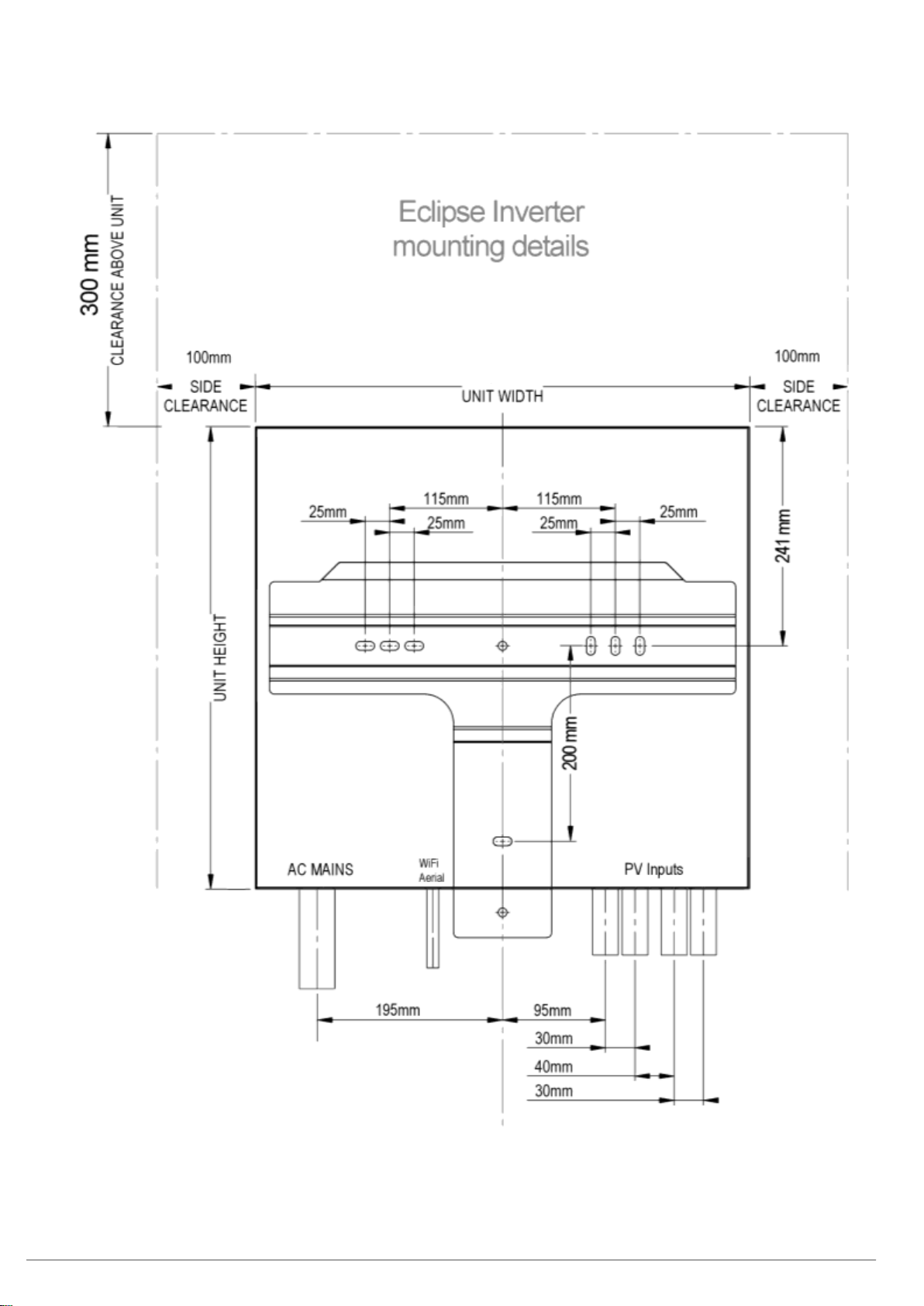
Mounting Location Dimension
When selecting where to install your Eclipse Inverter, ensure the Inverter meets minimum clearances with
respect to the selected load bearing mounting points.
514mm
512mm

MIL-Solar Eclipse series Installation and Operation Manual PNo 6569 Rev 5 Page 9of 52
WiFi Access
If the Eclipse Inverter’s WiFi connection is to be used continually by the customer, then consideration must
be given to any metal structures near or around the Inverter which can affect the WiFi signal.
Mounting
The Eclipse Inverter must be attached to a flat surface such as timber, masonry or a dedicated pole
assembly. The mounting bracket contains eight pre-drilled 8mm holes for attaching it to the wall.
Mark and drill at least four mounting holes, using the bracket as a template and attach the mounting bracket
securely to the wall.
All cables must have sufficient length and bend radius before entry into conduit so that strain is not placed on
the plugs or sockets where they connect to the inverter.
Weight Bearing
The wall structure on which the Inverter is to be mounted must adequately support its weight of 23 kg.
A minimum of four M6 fasteners must be used to securely install the mounting bracket onto the supporting
structure. Always use correct fasteners for the structure being fixed to.
CAUTION –Wall mounting strength
DO NOT mount on plasterboard, thin sheet cladding or sheetmetal unless you can
absolutely ensure that all mounting points are fixed into suitably supporting structural
members such as timber or metal studs.
CAUTION –Dissimilar metals
DO NOT mount directly onto galvanised steel.
WARRANTY
Installing the Inverter incorrectly will invalidate the warranty.
Please see Eclipse Inverter Australian Warranty on page 52 for terms and conditions.

Page 10 of 52 MIL-Solar Eclipse series Installation and Operation Manual PNo 6569 Rev 5
Install Inverter on mounting bracket
Lift and place the top of the Eclipse Inverter over the mounting bracket and lower it until the Inverter weight is
borne by the bracket.
Slide slightly from side to side to ensure that it has dropped into its fully seated position.
Secure the Inverter to the bracket
Before undertaking any wiring or connections, the Inverter must be secured to the
mounting bracket using the M5 fastener provided.
CAUTION –Manual Handling
The Inverter weighs over 23 kg
Care must be taken when lifting and placing the Inverter on mounting bracket.

MIL-Solar Eclipse series Installation and Operation Manual PNo 6569 Rev 5 Page 11 of 52
WIRING
Overall System Wiring Diagram
This diagram shows the full wiring diagram of an Eclipse Inverter including the optional power
meter. The Export Limit and MyPower features of the Inverter require the installation of the power
meter in the overall supply to the installation. As shown below, this power meter must be installed
such that it measures the total site power at the point of connection to the Grid supply.
DANGER
ELECTRICAL SAFETY STANDARDS - QUALIFIED PERSONNEL ONLY
All wiring must be in strict accordance with AS/NZS 4777.1, AS/NZS 3000 and AS/NZS
5033. All wiring and electrical works must be carried out by suitably qualified and licensed
persons.
CAUTION
Using undersized wiring can result in a serious safety and fire risk to equipment and
property.
SELV DATA Connection - Communications Wiring
AC
Isolator
DC
Isolators
(Optional)
AC
Circuit
Breaker
Page 12 of 52 MIL-Solar Eclipse series Installation and Operation Manual PNo 6569 Rev 5
Mains Connection
Recommended AC circuit breaker
The breaker must be rated for bidirectional power flow at 32A. Sizing of all AC wiring for the Inverter must
comply with AS/NZS electrical standards in accordance with the AC breaker and isolator employed.
Wire Size
Wire size is important, larger wires will reduce voltage rises, power losses and increase
system efficiency.
AS4777.1 has requirements for wire size to limit voltage rise.
AC Isolator
The AC connection must comply with Section 4 of AS/NZS 4777.1. The AC wiring scheme to the Inverter
must include an isolating device in compliance with this standard and be capable of safely disconnecting
under conditions of the maximum ratings as specified above.
AC Mains connection to the Inverter
The AC Mains connection to the Eclipse Inverter is by way of an external connector. Ensure there is
sufficient cable length and bend radius so that the connector is secured to the inverter AC socket in a
straight line and not under strain when installed. The connector body must not press against any conduit or
support the inverter when mounted on the supplied bracket.
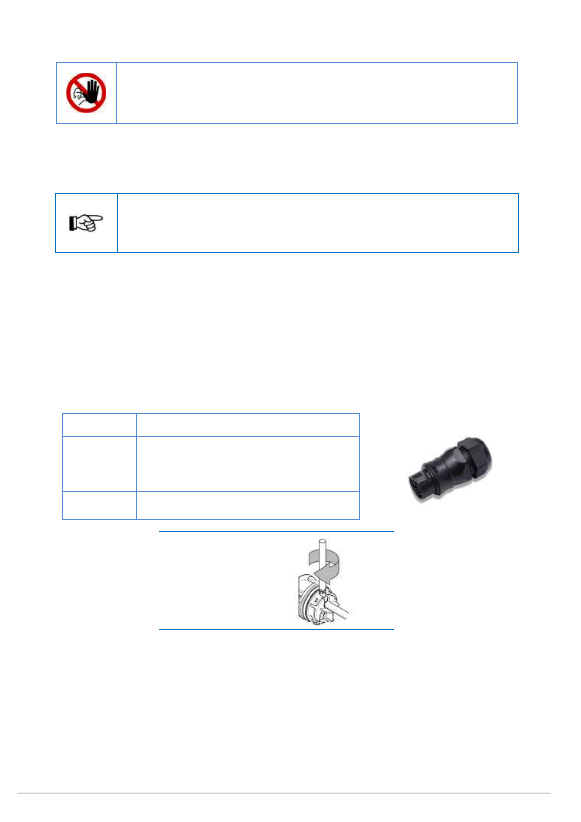
Description
Female, 3-pole circular connector for permanent
installation according to IEC 61535
Voltage
rating
250 V
Current
rating
32 A with 6 mm² wiring
IP rating
IP66/68
Screw terminal
tightening torque:
0.8 –1 Nm
Protective Earthing
The protective earth connection provided by the Inverter AC Mains connector is for protective earthing of the
Inverter only. Do not use the Inverter protective earth for earthing other parts of the system.
Protective earthing of exposed metal Solar PV module frames and Solar PV Array mounting frames must be
in accordance with AS/NZS 5033.
Protective earthing conductor - minimum cross-sectional area
The protective earthing conductor cross-sectional area must be in accordance with AS/NZS 3000.
DANGER
ELECTRICAL SAFETY STANDARDS - QUALIFIED PERSONNEL ONLY
All wiring must be in strict accordance with AS/NZS 4777.1, AS/NZS 3000 and AS/NZS
5033. All wiring and electrical works must be carried out by suitably qualified and licensed
persons.

MIL-Solar Eclipse series Installation and Operation Manual PNo 6569 Rev 5 Page 13 of 52
Solar PV Input
Solar PV Input - Maximum Ratings
PV 1
PV 2
Maximum Input
Voltage
Maximum Operating Input Current
750 V
12 A
12 A
Solar PV Isolator
All PV connections must comply with Section 4 of AS/NZS 4777.1. All PV array wiring connected to the
Inverter must include isolating devices in compliance with AS/NZS 5033 capable of safely disconnecting
under conditions of the maximum input ratings as specified above.
If two different PV circuits are to be used for the dual, independent Inverter PV inputs, then two appropriately
rated isolators are required or a combined isolator capable of breaking both circuits independently.
Solar PV Array –Cable Connectors
POSITIVE
NEGATIVE
Physical
*Units in mm
*Units in mm
Description
Cable Plug
MC4 (+)
Cable receptacle
MC4 (-)
Terminations of the PV system wiring to the connectors must be carried out in strict accordance with the
connector manufacturer’s instructions and using the specified tools as applicable. Ensure there is sufficient
cable length and bend radius so that the cable connector is secured to the inverter PV inputs in a straight
line and not under strain when installed.
DANGER
ELECTRICAL SAFETY STANDARDS - QUALIFIED PERSONNEL ONLY
All wiring must be in strict accordance with AS/NZS 4777.1, AS/NZS 3000 and AS/NZS
5033. All wiring and electrical works must be carried out by suitably qualified and licensed
persons.
Panel Ratings
All PV panels and modules used with an Eclipse Inverter must have an IEC 61730 Class A
rating as required by IEC 62109.
CAUTION
Solar PV arrays input PV1 and PV2 connected to the Eclipse Inverter must be isolated
from earth.
CAUTION –Do not substitute alternate connectors!
Only use the MC4 connectors provided with the Inverter.
-
37.00
~63.00
19.50
+
~61.00
35.00
19.50

Page 14 of 52 MIL-Solar Eclipse series Installation and Operation Manual PNo 6569 Rev 5
Data Connector
The Data Connector is used to connect the follow optional features to the Eclipse
Inverter.
External Fault Alarm
Demand Response Enabling Device (DRED)
Power Meter Communication
Detailed instructions for wiring each of these features are described in the following
sections.
If installing multiple of these features plan ahead when wiring the Data Connector.
Data Connector Wiring
All wiring connected to the terminals of the Eclipse Inverter Data Connector must:
Only be connected to SELV or PELV circuits as per AS/NZS 3000 that do not exceed 25 Vac or 60 V
ripple free DC under both normal and single fault conditions.
Prevent a single fault such as a loose wire or cut insulation resulting in an unsafe condition.
Use Clipsal 5005C305B C-BUS Cat 5E or equivalent with an outer insulation rated for switchboard
installations.
Ensure there is sufficient cable length and bend radius so that the cable connector is secured to the
inverter data socket in a straight line and not under strain when installed.
Fault Tests and Alarm
Since July, 2015, all Inverters sold and installed in Australia must be certified as compliant to the electrical
safety standard IEC 62109 parts 1 and 2.
A feature of this safety standard is the requirement for automatic testing and detection of system wiring and
fault conditions by the Inverter.
Where the Inverter determines a fault an indication is provided to the User by the LED Status Indicators.
These fault tests include:
Solar PV array insulation –Alarm
RCD Earth Leakage –Alarm
Grid disconnect relay –Alarm
Self tests of the fault detection circuits
AC mis-wiring
Alarm - LED and User Display (WiFi)
All faults are displayed on the Inverter LED’s as detailed on page 25. The Alarm faults are
displayed on the User Display by WiFi
Alarm - Email
The Inverter will automatically send an Alarm by email to MIL-Solar or the Installer as the
primary form of Alarm alert (via WiFi network connection).
Alarm messages identify the Inverter as well as the type of fault detected.
External Alarm Output (optional)
The Eclipse Inverter provides for the connection of an optional local Alarm indicator. The Alarm output
connection is a voltage free, normally open relay contact which closes on Alarm. The external alarm wiring
and voltage supply must be SELV or PELV maximum 25 Vac or 30 Vdc
Contact Ratings:
Maximum Voltage: 30V DC
Maximum Current: 1A –resistive only
DANGER
All data connection wiring must only be carried out by a suitably qualified and licensed
person.
Failure to install the data connector wiring as specified could result in an electrical shock
hazard leading to death or serious injury or potential fire risk.
DANGER
All external alarm output wiring must only be carried out by a suitably qualified and
licensed person.
Failure to install the external alarm output wiring as specified could result in an electrical
shock hazard leading to death or serious injury or potential fire risk.
Spare Part No. 6800
MIL-Solar Eclipse series Installation and Operation Manual PNo 6569 Rev 5 Page 15 of 52
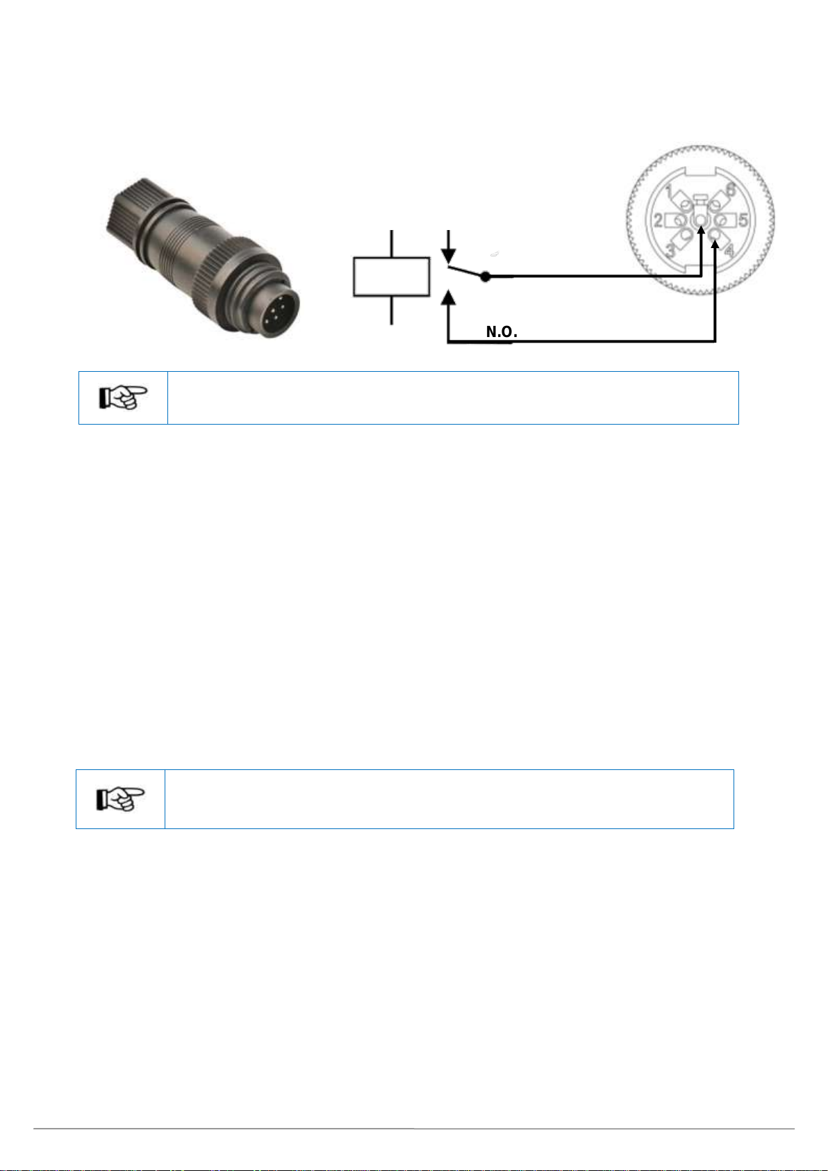
External Alarm Installation (optional)
The Eclipse Inverter is supplied with a screw terminal Data Connector for the data connections and the
optional Alarm. It comprises of two parts –terminal insert and outer housing. To access the pin screw
terminals, unscrew the outer housing from the terminal insert.
Multiple Data Circuits
The Alarm output uses only two of the seven pins in the Data Connector. Ensure to wire
all of the required data cables before closing the connector.
External Alarm Output Wiring
All External Alarm Output Wiring must:
Only be connected to SELV or PELV circuits as per AS/NZS 3000 that do not exceed 25 Vac or 60 V
ripple free DC under both normal and single fault conditions.
Prevent a single fault such as a loose wire or cut insulation resulting in an unsafe condition.
Use Clipsal 5005C305B. C-BUS Cat 5E or equivalent with an outer insulation rated for switchboard
installations.
DRED (optional)
AS/NZS AS4777.2-2015 requires the capability for an Inverter to be connected to a Demand Response
Enabling Device (DRED). The DRED device can control various power output modes of the Inverter
including demanding disconnection from the Grid.
Most installations of inverters of 5kW output or less do not have DRED devices.
Demand Response Mode - DRM 0
Before getting started
Plan and review:
Location of the DRED device provided by the utility, likely in the site switchboard
Connection and termination details at the DRED device
Route for data cabling from the DRED device to the Eclipse Inverter
No DRED required
If the installation does not have a DRED device, then no action is required.
The DRM 0 connection pins should be left open circuit –no connections.
Inverter Alarm connector wiring
Pin 4
N.O.
COM
Spare Part No. 6800
Pin 7
Data Connector
Inside view of screw
terminals
Close on Alarm
Page 16 of 52 MIL-Solar Eclipse series Installation and Operation Manual PNo 6569 Rev 5
Spare Part No. 6800
Installing DRED connection
DRED Wiring
All DRED wiring must:
Only be connected to SELV or PELV circuits as per AS/NZS 3000 that do not exceed 25 Vac or 60 V
ripple free DC under both normal and single fault conditions.
Prevent a single fault such as a loose wire or cut insulation resulting in an unsafe condition.
Use Clipsal 5005C305B. C-BUS Cat 5E or equivalent with an outer insulation rated for switchboard
installations.
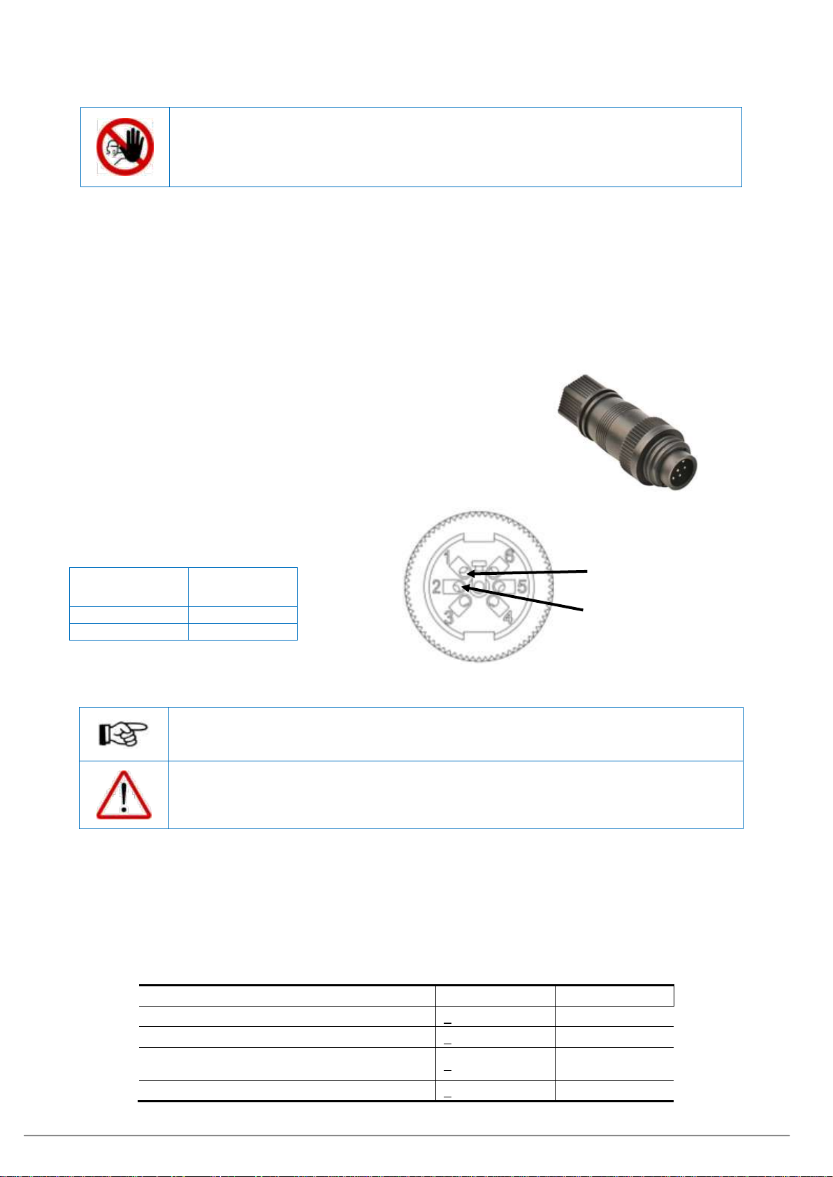
Data Connector
The Eclipse Inverters is supplied with a screw terminal Data
Connector for the data connections to the Inverter. This connector is
also used for the DRM 0 connection.
DRM 0 connection
DRM 0 mode is enabled via connections RefGen and Com
Load/DRM0 (Refer AS4777.2_2015)
DRM 0
Data
Connector
COM LOAD/0
1
REF GEN/0
2
Multiple Data Circuits
The DRED connection uses only two of the seven pins in the connector. Ensure to wire all
of the required cables before closing the connector.
CAUTION
All data connections to the Inverter are SELV or PELV.
Suitable insulated cable and/or protection must be provided where the cable is routed
through the switchboard for connection to the DRED device.
DRED Data Cable Specification
AS4777.2 specifies the following rating for the DRED connection:
TABLE 6
RJ45 SOCKET AND TERMINAL BLOCK SPECIFICATIONS
Property
Value
Symbol
Current rating
> 1.5
A
Voltage rating (V r.m.s.)
> 125
V
Dielectric strength
(V r.m.s. 50 Hz, 1 min)
> 1000
V
Insulation resistance (MΩ min 500 V)
> 500
M Ω
DANGER
All DRED wiring must only be carried out by a suitably qualified and licensed person.
Failure to install the DRED Wiring as specified could result in an electrical shock hazard
leading to death or serious injury or potential fire risk.
REF GEN/0
Data Connector
Inside view of
screw terminals
COM LOAD/0
MIL-Solar Eclipse series Installation and Operation Manual PNo 6569 Rev 5 Page 17 of 52
Power Meter Installation (optional)
The MIL-Solar Eclipse Inverter has an optional feature that enables the Inverter to monitor the power usage
of the installation. This feature shows power usage and power export/import in real time through the
Inverter’s User Interface, enabling the user to better manage their power. See My Power on page 35 for
further details.
For the MyPower feature, a MIL-Solar Power Meter must be installed in the main switchboard which is
connected to the AC Mains Grid.
The Power Meter can be either single phase or 3 phase depending on the installation’s Grid supply.
The Power Meter also enables the use of the Export Limit feature, limiting the amount of power exported to
the grid, which may be a requirement of the power distribution company. See Export Limit Operation on
page 38 for further details.
Before getting started
Plan and review:
Single phase or 3 phase meter being used.
Possible locations for the Power Meter in the site switchboard.
Access to the incoming AC Mains supply for connection through the Power Meter.
Route for data cabling from the Power Meter to the Eclipse Inverter.
Ensure that you have the Data Connector supplied for the data cable connection to the Eclipse Inverter and
sufficient length of suitable data cable.
DANGER
Installation and wiring of the Power Meter in the switchboard MUST ONLY be carried out
by a suitably qualified and licensed person.
Failure to install the power meter correctly could result in an electrical shock hazard
leading to death or serious injury and potential fire risk.
NOTICE
The Power Meters are pre-configured, altering the Power Meter’s internal settings will
prevent the use of the Eclipse Inverter MyPower features.

Page 18 of 52 MIL-Solar Eclipse series Installation and Operation Manual PNo 6569 Rev 5
Power Meter Wiring
The Power Meter must be wired into the main switchboard feed immediately after the main isolator, but
before the connection point for the Eclipse Inverter. Use the appropriate Power Meter to match the number
of phases at the site. The Power Meter has a maximum rating of 100 A.
Single Phase Power Meter Wiring
3 Phase Power Meter Wiring
Single Phase
Term
Description
1
Incoming Grid L-IN Active
2
L-OUT Active Outgoing to
installation switchboard
3
Neutral
8
Data B
9
Data A
4-7
Unused
3 Phase
Term
Description
1
Incoming Grid L1 (Red)
2
Incoming Grid L2 (White)
3
Incoming Grid L3 (Blue)
4
Incoming N (Black)
5
Outgoing L1 (Red)
6
Outgoing L2 (White)
7
Outgoing L3 (Blue)
8
Outgoing N (Black)
9
Data B
10
Data A
11-15
Un-used
Inverter Phase
The Inverter can be connected on any of the 3 phases. Ensure to note down the phase and
update it in the Inverter User Interface, see Configuring the Inverter for MyPower on page 37
for details.
0000.00
11
14
12
9
13
10
5
6
7
8
1
2
3
4
15
GRID
L1
L2
L3
N
L1
L2
L3
N
INSTALLATION
Data A
Data B
INSTALLATION
GRID
Data A
Data B

MIL-Solar Eclipse series Installation and Operation Manual PNo 6569 Rev 5 Page 19 of 52
Power Meter Data Wiring
A data connection must be made between the Power Meter and the Eclipse Inverter.
Power Meter Data Wiring
All Power Meter data wiring must:
Only be connected to SELV or PELV circuits as per AS/NZS 3000 that do not exceed 25 V AC or 60 V
ripple free DC under both normal and single fault conditions.
Prevent a single fault such as a loose wire or cut insulation resulting in an unsafe condition.
Twisted pair. AWG 22 –26.
The Data ‘A’ and Data ‘B’ connections must use one twisted pair.
Inverter Data Connector
The Eclipse Inverter is supplied with a screw terminal Data Connector for terminating the Power Meter data
cable at the Inverter. It is comprises of two parts –a terminal insert and an outer housing.
Power Meter Data Connection Wiring
Wire the data cable between the Power Meter and Inverter using the
following table.
Multiple Data Circuits
The Power Meter connection uses only two of the seven pins in the connector. Ensure to
wire all of the required cables before closing the connector.
DANGER
All data connection wiring must only be carried out by a suitably qualified and licensed
person.
Failure to install the data connection wiring as specified could result in an electrical shock
hazard leading to death or serious injury or potential fire risk.
Use Clipsal 5005C305B. C-BUS Cat 5E or equivalent with an outer insulation rated for switchboard
installations.
Terminal
Connector
(Inverter end)
1 Phase
Power Meter
3 Phase
Power Meter
Data A
5
9
10
Data B
6
8
9
Spare Part No. 6800
A
B
A
B
Screen
(If fitted)
Power Meter
Inverter Cable connector
Data B
Data A
Data Connector
Inside view of
screw terminals

Page 20 of 52 MIL-Solar Eclipse series Installation and Operation Manual PNo 6569 Rev 5
Single Phase Power Meter - Data Cable Termination
Restrain the data cable to the Power Meter housing using a cable tie supplied with the MyPower meter as
shown below.
Three Phase Power Meter - Data Cable Insulation and Termination
The data cable at the 3 phase meter must be insulated from the active and neutral terminals using the
MIL-Solar insulator PNo 6958 provided with the Power Meter.
Fit all AC L and N conductors to the Power Meter.
Fit the MIL-Solar Insulator PNo 6958 so it covers the AC L and N terminals.
Fit the data wiring to the Power Meter.
Close the cover and secure in place with the cable ties supplied. This restrains the data cable and the
insulator.
DANGER
All data connection wiring must only be carried out by a suitably qualified and licensed
person.
Failure to install Insulator connection wiring as specified could result in an electrical shock
hazard leading to death or serious injury or potential fire risk.
Insulator PNo 6958
Other manuals for Eclipse 5000-II
2
Table of contents
Other MIL-Solar Inverter manuals


Popular Inverter manuals by other brands


PowMr
PowMr POW-SunSmart 8KL3 user manual

Briggs & Stratton
Briggs & Stratton 7000 WATT 206484GS Installation and operator's manual

Shindaiwa
Shindaiwa DG150MI Owner's and operator's manual

Kathrein
Kathrein Video Sweep Generator MVG 10 Operator's manual

GreenWorks
GreenWorks 9300000 owner's manual

Hitachi
Hitachi L300P Series Specifications

Growatt
Growatt 10000HYP installation guide

Huawei
Huawei SUN2000-30KTL-A user manual

GYS
GYS Gyspot BP.LC-S7-230V user manual

FLOWTECH
FLOWTECH flowcon Operation and maintenance manual

Generac Power Systems
Generac Power Systems 006071-0 owner's manual

Peak Performance
Peak Performance PKC0BM Owner's manual and warranty information