Millennium R/C Micro-SS Micro SSX User manual

Dimensions: 21 ½” wing span
Flying Weight: 4 ½ -5 ¼ oz.
(with recommended setup)
MillenniumRCpresentsMicroSSXBuildKit
Introduction:
This is the Micro SSX™ build-it-yourself kit. It is identical to the ARF version with some
enhancements to make it easier to build. All the parts are laser cut and interlocking so no pins are
needed to assemble this kit. The wing can be assembled in ½ an hour by most modelers.
The MicroSSX™ is a miniature version of the Millennium R/C Slow Stick X™ Electric Park
Flyer. It is a fun-to-fly fully aerobatic electric R/C airplane that can be taken anywhere! Fly it indoors
or out!!
Adult supervision recommended for children 15 and under. R/C Airplanes should be flown
following safety guidelines provided by the AMA (Academy of Model Aeronautics).
CAUTION: This is not a toy!
Recommendations:
1. Read through each step before starting assembly.
2. After removing all the pieces from packaging, inspect to make sure there are no broken or
missing parts.
3. Check off each completed step to help keep from losing your place.
DISCLAIMER:
Millennium R/C assumes no responsibility for any accident or injury to persons or damage to property.
TM
IMPORTANT:
DO NOT GLUE UNTIL INSTRUCTED TO DO SO!
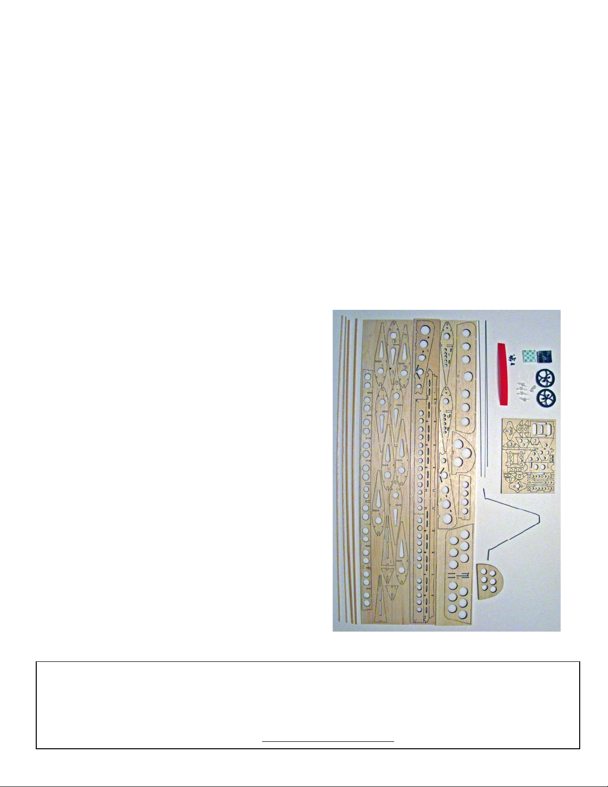
List of Provided Kit Parts:
1. Laser-cut balsa parts for Micro SSX™ wing/tail
sections
2. 4 micro control horns
3. 2 micro light wheels
4. 2 wheel retainers
5. Wire for push rods, aileron linkage and tail skid
6. Preformed wire main landing gear
7. 15” Wrapped carbon fuselage
8. Velcro pads
9. Velcro “One Wrap” Battery strap (RED)
10. Servo tape (Used to hold speed control in
position)
11. 6 # 0 - ¼ sheet metal screws (Servos)
12. 2 # 1 – ¼ sheet metal screws (Motor)
Additional Items Required:
1. Cyanoacrylate or CA Glue (thin and thick)
2. Hobby knife
3. 220-grit sandpaper
4. Sanding block
5. Hinge tape (recommend 3M Scotch ™ ¾”
Transparent Tape)
6. Ruler
7. Square
8. Razor saw
9. Hand drill or small drill with #56 (.046”) drill bit.
10. 1/16” drill bit.
11. Micro screwdriver set
12. Micro-receiver (recommend Castle Creations
Berg)
13. Motor (recommend Hacker A10-12S brushless
outrunner motor, 2900 Kv)
14. Speed control (recommend 5-9 amps, as
recommended by motor)
15. Propeller (as recommended by motor
manufacturer)
16. Three servos (less than 6 grams each,
recommended. Ideal is 4 grams)
17. Battery (recommend 2-cell lithium polymer
battery, 300-480 mAh) Please adhere to
manufacturer’s safety guidelines.
* * * * * * * * * * * * * * * * * * * * * * * * * * *
Check out the Micro SSX build thread
on R/C Groups with full-color
pictures and instruction updates.
Find the link at our website:
www.millenniumrc.com
ADDENDUM:
Part P8 (plywood piece) is no longer
needed for main spar brace, as it has
been determined that wing design
provides sufficient strength.
* * * * * * * * * * * * * * * * * * * * * * * * * *
Parts provided in Micro SSX Build Kit
If you should find a part missing or damaged, or have any questions about assembly, please contact us:
Millennium R/C
12859 Lower River Blvd., Orlando, FL 32828
Phone: 407-208-9745 / Fax: 866-799-2372
3
Assembly Instructions:
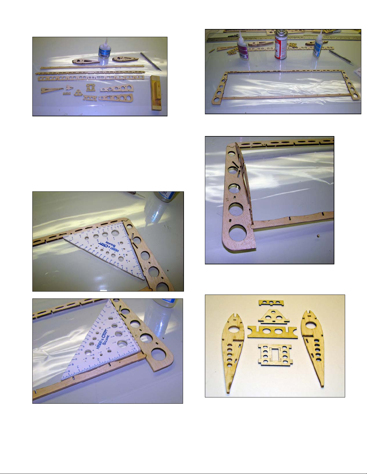
1. Cut - don’t break the balsa and plywood
parts from the parts sheets. Breaking the
parts out of the sheets can damage the
parts. Remove all “W” balsa parts and P8,
P9, P10 and P11 plywood parts. Sand
smooth the break points. Parts above are
prepped and ready for assembly.
2. Assemble a frame from parts W1, W4 and
W5. Use a small square to insure a square
corner. Use thin CA at corners.
Completed wing frame
3. Install ribs W6 at wing tips. Bend the part
slightly to fit in place.
Center ribs W2, servo deck P10, front wing
saddle P11, P9 and main spar brace
4. Assemble wing center section from parts
W2, P8, P10 and P11. (Note: P8 no longer
used)

4
5. Install the servo deck P10 so that the flush
mounting tabs are closest to the spar.
6. Install front wing saddle P11. (P8 shown,
but no longer used)
Assembled wing center section from parts
W2, P8, P10 and P11 (P8 no longer used)
7. Install Center section into the leading edge.
8. Insert remaining ribs W7 into the leading
edge.
9. Install spar crutch W10, Use caution!
10. Sand smooth one side of the 3/32 spar
sticks. Test fit them into the ribs. If sticks
protrude beyond the ribs then sand the
sticks till they are flush with the top of ribs.
Center ribs on trailing edge and tack glue.
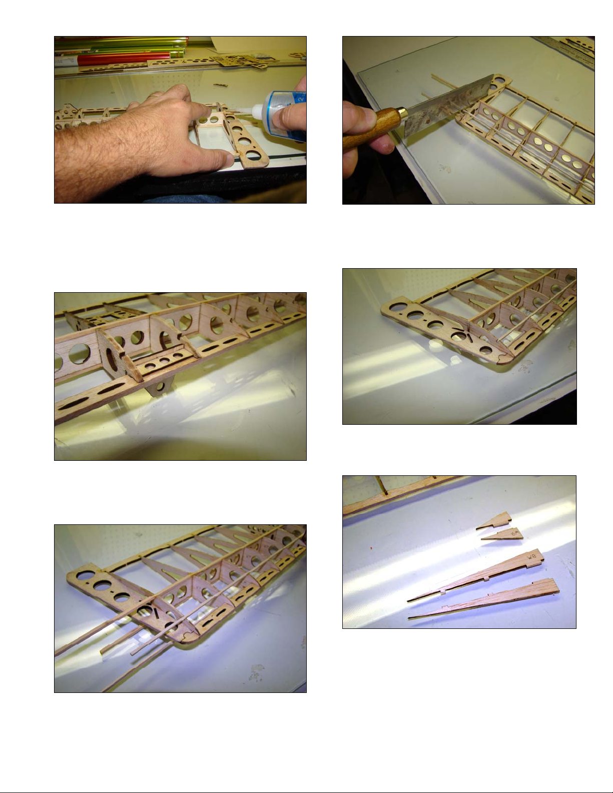
5
11. Hold spar stick in position and glue. Be sure
that the spar stringers are butted up against
the spar crutch W10. This forms a very
strong “ I ” beam.
12. Install front wing saddle brace P9. Make
sure front wing saddle is square to the wing
frame and glue with thin CA.
13. Install leading edge stringers top and
bottom. Make sure they are flush with ribs
and sanded on one side before gluing. Glue
all remaining joints of the wing.
14. Remove excess spar stick and leading edge
stringers.
15. Sand flush with rib W6.
16. Prepare wing tip braces for installation.
(Sand and Split)
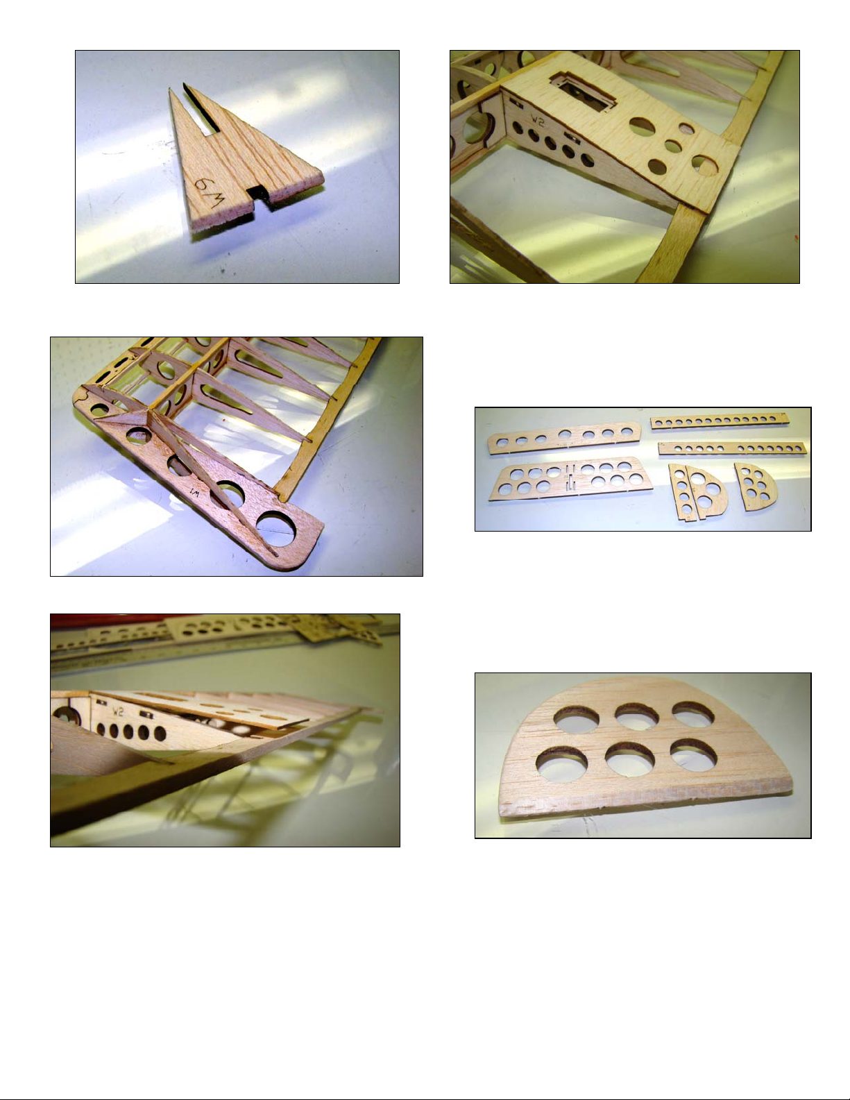
6
17. Bevel wide end of W9 before assembly.
Completed wing tip
18. Install servo deck cover. First glue to spar.
Then, following the contour of rib; glue the
trailing edge.
19. Flip the wing over and glue the cover to the
inside. Sand cover flush with trailing edge.
Tail Section
1. Glue together vertical stab pieces S3 and
S4. Prepare remaining parts to be covered.
Remove burnt edges with 220 sand paper
and round off corners. Stop sanding when
burnt edge is faint. Do not distort the original
shape of the part.
2. Bevel leading edge of rudder elevator and
ailerons 45 degrees.
3. Cover tail section and wing with light model
covering such as World Model Lightex or So
Lite, following manufacturer’s instructions.
7
Assembly of the control surfaces
1. Start by removing the horizontal stabilizer
and vertical stabilizer from the packing
bags. Remove the four pieces of masking
tape holding the elevator to the stabilizer.
2. Tape a length of Scotch tape™ along the
rear trailing edge of the horizontal stabilizer
and secure with your finger (either side is
fine). Now, flip the stabilizer and place on a
work surface. See diagram below:
3. Now, take the elevator. You will see that the
elevator has a ‘beveled’ edge. This is
important in creating the hinge. Ensure that
the beveled edge is pointing up, and while
holding at a 45° angle, place up against the
trailing edge of the horizontal stabilizer and
secure the hinge tape to the elevator with
your finger. See diagrams below:
4. Turn the stabilizer assembly over, and
carefully fold the elevator back onto the
stabilizer.
5. Tape another length of Scotch tape™ along
the bottom hinge line and secure with your
finger.
6. Fold the elevator back to normal position.
Test the hinge by pulling gently on the
control surface. Cut off any excess tape
overhanging the stabilizer sides.
7. Repeat the steps 1. thru 6. for the rudder
and ailerons.
8. Install the control horns by pushing the
horns through the holes located in the
vertical and horizontal stabilizers. The
vertical stabilizer control horn must be
installed on the opposite side of the beveled
edge. The horizontal stabilizer horn will be
installed through the top on the opposite
side of the vertical stabilizer horn. Secure
the control horns with thick CA glue.
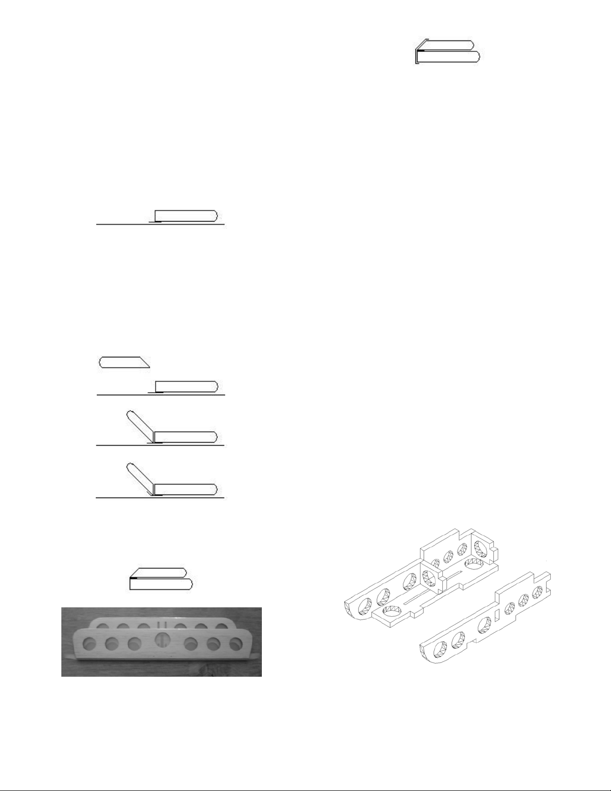
Assembly of the plywood hardware
1. Open the bag containing the plywood
pieces carefully. The hardware bag contains
many small items that can get misplaced
easily. Remove the parts for the tail support
bracket and assemble with thick CA glue as
shown in the diagram below. Ensure that no
excess glue travels into the holes for the
fuselage. The small square cross pieces are
installed with one located at the leading
edge of the mount and other centered on
the tail skid slot. Refer to the next diagram:
Note: New style tail mount.
2. Build two servo mounts with the parts
provided using thick CA glue. Ensure that
no excess glue travels into the holes for the
fuselage. Refer to the picture below:
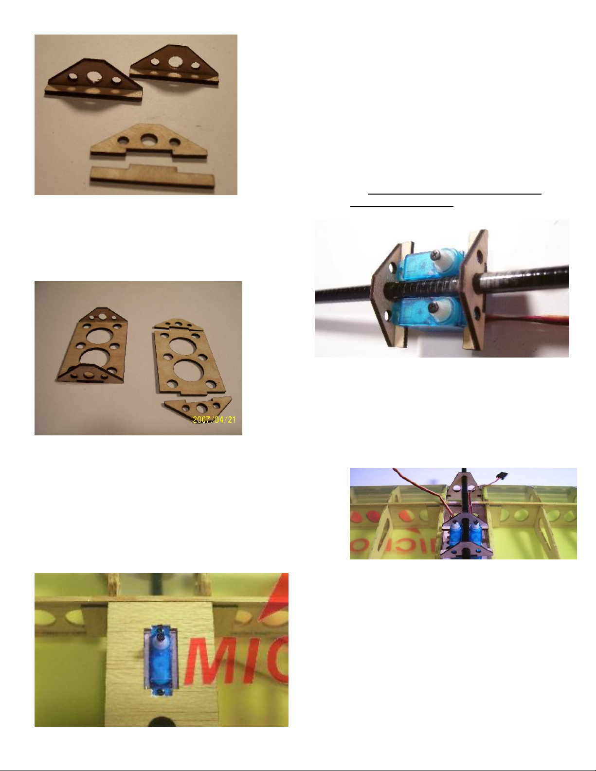
8
3. Assemble the battery mount pieces with
thick CA Glue. Ensure that no excess glue
travels into the holes for the fuselage. Refer
to the picture below:
Main Wing & Fuselage Construction
1. Carefully trim the covering from the servo
mount on the top center of the wing, being
careful not to tear the covering. Trim the
servo mount if necessary. Feed the servo
wire through the hole and install the servo.
Use provided #0 -1/4 black screws to mount
the servo.
2. Take the fuselage carbon stick and slide the
servo mounts previously assembled in #11
onto the fuselage. If necessary, shave a
little material around the holes off the
mounts so that they fit onto the fuselage.
DO NOT sand or lubricate the fuselage
stick.
3. Mount the servos as shown in the diagram
below. Use provided #0 -1/4 black screws to
mount the servo. DO NOT glue the mounts
to the fuselage stick until instructed to do
so. The servo mounts will accommodate
servos up to 7 grams.
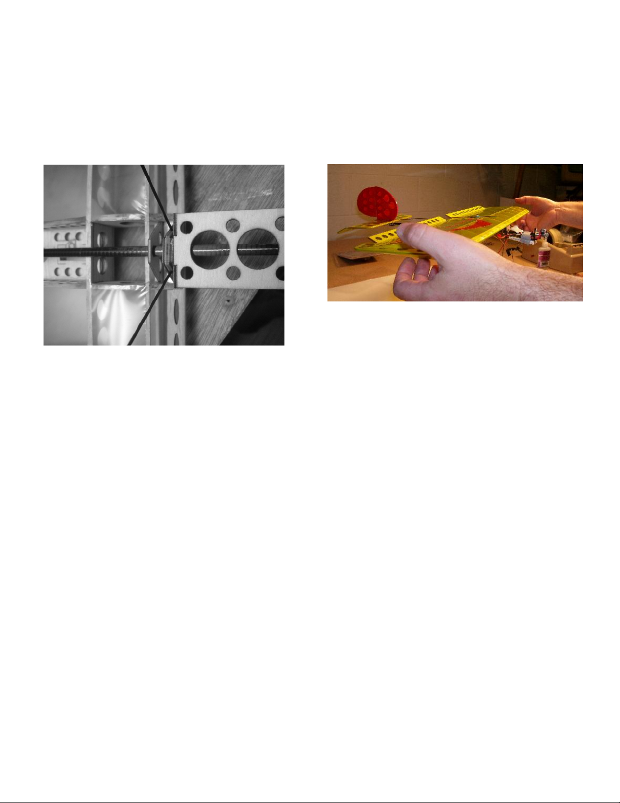
4. Slide the fuselage and servo assembly
through the front wing saddle, carving any
excess from the hole ONLY if necessary.
Feed servo wires through the holes in the
center spar towards the front of the wing.
Refer to the picture below:
5. Slide P12A onto the fuselage stick and glue
6-3/4” from the tail mount leading edge.
Slide P12 onto the fuselage and leave it
loose. Slide the tail mount onto the fuselage
end and align it so that it is square with the
flat edge of P12A. Glue it and allow the glue
to dry. Secure P12 to P12A with 2 #0-1/4
screw. Do not glue P12 to P12A. Slide the
servo assembly onto the front of the
fuselage, align it so that it is square with the
flat edge of P12A and glue it with CA glue.
Slide the fuselage assembly through the
front lower wing mount. P12 should be

9
glued to the leading edge of the trailing
edge piece of the wing. Align the wing so
that it -is parallel to the tail mount. Glue the
tail section vertical and horizontal stabilizer
together so they are square.
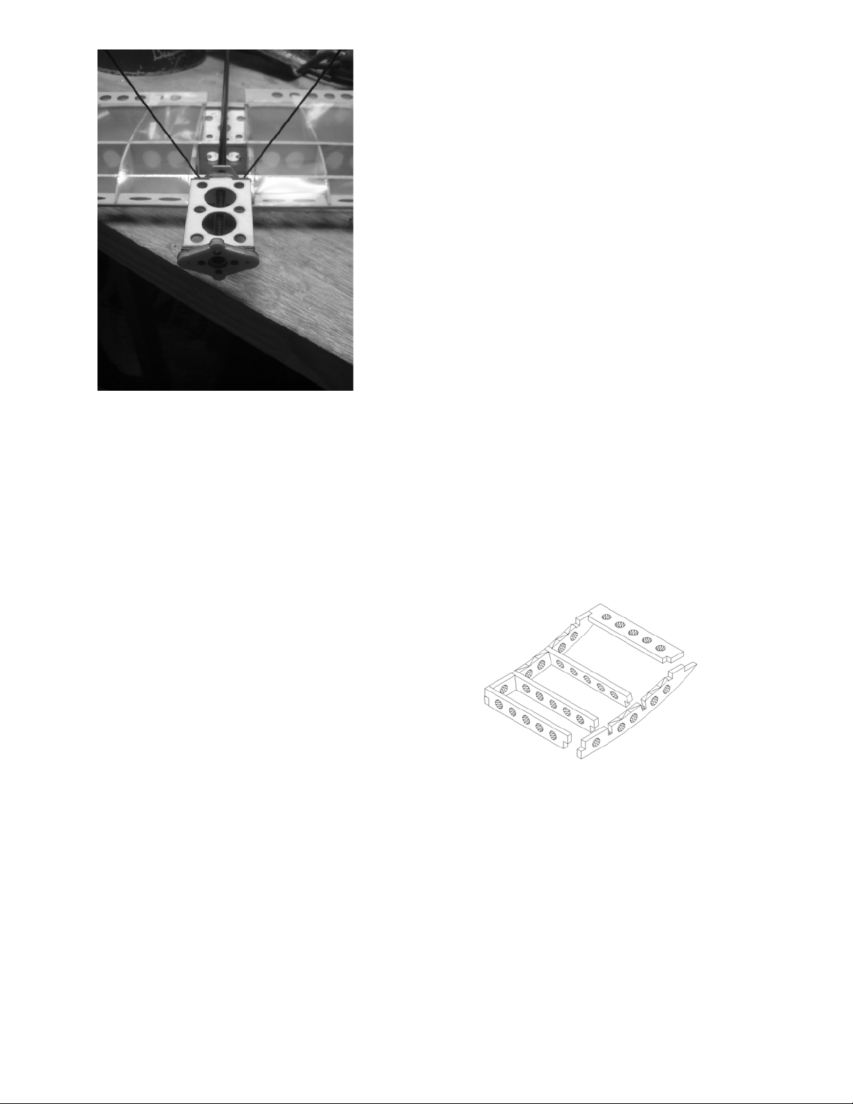
(Below) Installed rear wing saddle
Main Assembly
6. Return to the horizontal stabilizer,
previously assembled in sections 1. thru 8.
Depending on which side you chose to
install the control horn, depends on which
side you install the tail support bracket.
WITH THE CONTROL HORN ON THE
OTHER SIDE OF THE STABILIZER
carefully cut the covering away from the
slots in the stabilizer by using a sharp
modeling knife. Install the mount into the
horizontal stabilizer using thick, or slow
drying CA glue. The three circles of the tail
support bracket should point to the leading
edge of the stabilizer.
7. Now, slide the fuselage stick into the tail
mount support bracket, and secure using
thin CA glue. REAR TAIL MOUNT
SHOULD BE 3/8TH” PAST THE END OF
THE FUSELAGE STICK.
8. Locate the tail skid slot on the tail mount
bracket. Using a micro drill bit, drill a small
hole through the fuselage stick at the front
of the tail skid slot. Install the tail skid into
the drilled hole and locate in the slot.
Secure with thick CA glue. See next picture:

10
Drill hole to accept tail skid
Install tail skid into the tail support bracket
And secure with thick CA glue
9. Assemble the two motor mounts by gluing
the two pieces together with thick CA.
These will be glued onto the battery support
previously assembled in #11 later in these
directions. Refer to the following diagram:
10. The landing gear consists of 4 plywood
pieces. Locate these and assemble using
thick C.A glue as shown in the diagrams
below. Some light sanding of the internal
landing gear mounting pieces may be
required to maintain alignment.
11. Slide the landing gear onto the fuselage as
shown in the diagram below. Using thick
C.A glue, secure the landing gear bracket
onto the front wing saddle and leading edge
of the wing. DO NOT glue to the fuselage
stick yet. Attach the wheels with the
provided plastic collars.
11
12. Install the pushrod guide on the fuselage
stick. It is located half way down the
fuselage between the trailing edge of the
wing and the leading edge of the horizontal
stabilizer.
13. Slide the battery mount onto the front of the
fuselage. Again DO NOT glue the battery
mount to the fuselage.
Balancing & final fuselage assembly
In order to balance this model, a ‘dry’ assembly of
the fuselage is performed. The model is then
balanced and finally secured with C.A glue. Follow
the steps below to balance the model and finish
assembly.
1. Position the wing so that the front of the
landing gear mount is approximately 2 1/8”
from the front of the fuselage tube and lined
up with the leading edge of the wing. The
distance between the aileron trailing edge
and the leading edge of the horizontal stab
should be approximately 5-1/4”. Do not glue
the wing to the fuselage.
2. Setup motor and speed control as per
manufactures recommendations. Fit battery
and power unit to model so that wires are as
short as possible. This is a light model and
every little bit of extra weight counts.
3. Temporarily attach propeller, receiver,
antenna, motor, speed control, and battery
(using narrow Velcro strap) before
balancing. The receiver is typically strapped
or taped to the fuselage and a micro
antenna is used for this model.
4. The CG for this model is 1/8”inch to the rear
of the main spar. Balance the plane at the
CG by holding wings with your fingertips as
shown in the image below. Try to maintain
the distance from the front fuselage to the
leading edge of the wing at 2 1/8” by
adjusting positions of your hardware first. If
necessary, change position of your wing to
balance.
5. Once aircraft is balanced, adjust the
horizontal stabilizer so it is parallel to the
wing. Then glue the front and rear wing
saddles to the fuselage stick.
6. Position servo, battery and motor mounts.
The motor should have 2 ° of right and 2 °
of down thrust. This can be achieved by
shimming the motor or by offsetting the
motor mount during gluing. Glue the motor
mount to the fuselage and battery mount
using thick CA glue.
7. Square the vertical stabilizer to the
horizontal stabilizer. Glue the vertical
stabilizer to the horizontal stabilizer by
bleeding thin CA into the mount.
8. Install the control linkage. The aileron
control horns must be mounted through the
top of the control surface at this time and
glued at the same angle as aileron push
rods. Feed the rudder and elevator
pushrods through the rear pushrod guide
before attaching to servos. Use Z bends for
rudder and elevator servos. Be sure to
center your servos first.
9. Glue the motor mount to the front of the
battery holder. See picture below:
12
10. Permanently install receiver, motor and
speed control. Make sure your antenna
does not touch the carbon fiber fuselage or
any metal. Use double stick foam tape to
mount speed control to the top of battery
mount.
Control throws
Control throws are as follows:
Use Exponential if your radio has it the facility.
Elevator: 45 ° up and down 20° low rate
Rudder: 45 ° left and right
Ailerons: 45 ° up and down 20° low rate
Motor & Battery Setup
1. Use the motor mount provided with your
motor. Trim the motor mount so that it does
not extend beyond the plywood mount.
2. Keep wire leads as short as possible. Every
little bit of weight counts.
3. Use the provided double-sided foam tape to
secure the ESC to the plywood battery
holder.
4. Use the provided sticky back Velcro to
mount the battery to the plywood battery
holder. Place the hook side on the plywood
holder and the loop side on the battery. This
will hold the battery in place while you
secure the battery with the red Velcro strap.
Servo/Radio Setup Tips
•Use the small arms for all servos.
•Connect pushrods at outermost hole of
control horns and servo arms.
•Micro servo cases are typically press fit.
The bottom can easily be pulled apart and if
you don’t put it back correctly, you can ruin
the servo. I recommend using a piece of
clear tape and placing it so that it straddles
the bottom of the servo. This will keep the
bottom from falling off.
•Use a micro receiver such as the Berg 4L or
Micro Spectrum receiver.
•The spectrum receivers can easily be
placed inside the wing between the center
ribs.
•The Berg 4L can be secured to the fuselage
with a Velcro strap or tape.
•Use a Micro antenna with the Berg 4L
receiver, if possible.
•Do not allow your antenna to touch the
fuselage or pushrods during flight. This can
reduce the range of your receiver. The
fuselage of the Micro SSX is carbon fiber,
carbon is a conductor.
•Tip: Run servos for several cycles before
first flight. This will improve centering.
New Optional Receiver Hatch:
Main Wing Decal
1. Cut excess material from decal before
removing the backing.
2. Remove the protective backing to expose
the adhesive.
3. Add about 3 drops of dish soap to 2 pints of
clean water. Put it in a spray bottle and
spray the back of the decal.
4. Slide the decal into position and squeegee
the excess water from under the decal.
5. Allow the decal to dry overnight.
ENJOY YOUR NEW MICRO SSX!
Popular Toy manuals by other brands

ROBBE
ROBBE Corsair ARF FW004006 Building and operating instructions

CustomWorks
CustomWorks Enforcer GSX2 Assembly manual

V-tech
V-tech Marble Rush Starter Set Parents' guide

Spinmaster
Spinmaster DreamWorks GABBY'S DOLLHOUSE Pillow Cat's Sweet Dreams... Instruction guide

V-tech
V-tech Alphabert s Sonic Phonics user manual

ThinkGizmos
ThinkGizmos TG654 user manual

V-tech
V-tech Nitro Vision user manual

De Agostini
De Agostini Model Space MiG-29 manual

V-tech
V-tech SWITCH & GO DINOS Overseer the T-Rex Parents' guide

Modeltech
Modeltech Magic Extra 300L Instructions for final assembly

KNEX
KNEX Amazing Value Tub manual

V-tech
V-tech Toot-Toot Friends Pirate Ship Parents' guide


