Miller MILLER 400 DIVING HELMET User manual

© Miller Diving All Rights Reserved Document # 030715001
1
MILLER DIVING EQUIPMENT INC.
Miller 400 Diving Helmet
Maintenance Manual

© Miller Diving All Rights Reserved Document # 030715001
2
MILLER 400 DIVING HELMET OPERATIONS AND MAINTENANCE MANUAL
Part # 100-900
TABLE OF CONTENTS
WARRANTY ............................................................................................................................... 3
DEFINITIONS OF SIGNAL WORDS ........................................................................................ 4
IMPORTANT SAFETY INFORMATION .................................................................................. 5
SECTION 1: GENERAL INFORMATION
1-A INTRODUCTION ............................................................................................. 7
1-B GENERAL DESCRIPTION OF MILLER 400 ................................................ 7
SECTION 2: OPERATING INSTRUCTIONSAND PROCEDURES
2-A PRE-DIVE PROCEDURE .................................................................................8
2-B DRESSING INTO THE MILLER HELMET ....................................................8
2-C OPERATING INSTRUCTIONS .......................................................................9
2-D EMERGENCY PROCEDURES ........................................................................9
2-E RECOMMENDED MATERIALS FOR MAINTENANCE .............................10
SECTION 3: DESCRIPTIONS, MAINTENANCE AND REPLACEMENT
3-A HELMET SHELL ..............................................................................................12
3-B FACE PLATE AND FACE RING .....................................................................12
3-C NOSE CLEARING DEVICE ............................................................................13
3-D ORAL NASAL MASK .....................................................................................13
3-E FREEFLOW MANIFOLD ................................................................................14
3-F CHECK VALVE .................................................................................................14
3-G EMERGENCY VALVE .....................................................................................15
3-H SIDE EXHAUST ..............................................................................................16
3-H CAMS ................................................................................................................17
3-J DEMAND REGULATOR ................................................................................18
3-K FACE SEAL .....................................................................................................20
3-L HEAD HARNESS .............................................................................................20
3-M NECK RING ......................................................................................................20
3-N NECK RING GASKET......... ............................................................................21
3-O COMMUNICATIONS SYSTEM ......................................................................22
3-P FACE GUARD (optional) .................................................................................22
3-P WELDING SHIELD (optional) ........................................................................22
3-Q PREVENTATIVE MAINTENANCE ...............................................................22
SECTION 4: MILLER 400 PARTS LISTAND EXPLODED VIEW ....................................24
MILLER PRODUCT LINE
MILLER WEIGHT BELTS .........................................................................................................26
MILLER DIVING HARNESS ....................................................................................................26
MILLER BACKPACKS ...............................................................................................................27

© Miller Diving All Rights Reserved Document # 030715001
3
DANGER: Diving with compressed breathing gas is a hazardous activity. Even if you do
everything right there is always the potential for serious injury or death. No one piece of diving
equipment can prevent the possibility that you may be injured or killed any time you enter the
water.We do not herein make any effort to teach the principles of diving. It is our assumption
the reader is a qualified diver.
Warranty Information
Miller Diving warrants every new helmet to be free from defects in workmanship for a period of ninety (90)
days from date of purchase. This warranty does not cover rubber parts or communications components.
Should any part become defective due to workmanship during the warranty period, contact your nearest autho-
rized Miller dealer. If there is no dealer in your area, contact Miller Diving directly at (805) 965-8538, Fax (805)
966-5761, or E-Mail: [email protected]. You must have a return authorization number (RMA #) prior to
the return of any item. Upon approval from Miller Diving, return the defective part, freight prepaid to: Miller
Diving, 425 Garden Street, Santa Barbara, CA93101, USA. The part will be repaired or replaced at no charge as
deemed necessary.
This warranty becomes null and void if:
1. The product is not registered with Miller Diving within ten (10) days of purchase.
2. The product has not been properly serviced and maintained according to this manual.
3. Unauthorized modifications have been made to the product.
4. The product has been abused or subjected to conditions which are unusual or exceed the product's
intended service.

© Miller Diving All Rights Reserved Document # 030715001
4
WARNING: Diese Mitteilung ist wichtig. Bitte übersetzen lassen.
WARNING: Ceci est important. Veuillez traduire.
WARNING: Quest è un avviso importante. Tradurlo.
WARNING: Este es un aviso importante. Sirvase mandario traducir.
WARNING: Este é um aviso importante. Queira mandá-lo traduzir.
DEFINITIONS OF SIGNAL WORDS USED IN THIS MANUAL
For your protection, pay particular attention to items identified by signal words in this manual. These terms are
identified as, CAUTION, WARNING AND DANGER. It is especially important for you to read and understand
these signal words.
CAUTION: This word indicates a potentially hazardous situation which, if not avoided,
may result in minor or moderate injury. It may also be used to alert against unsafe practices.
WARNING: This word indicates a potentially hazardous situation which, if not avoided,
could result in death or serious injury.
DANGER: This word indicates an imminently hazardous situation, which if not avoided,
will result in death or serious injury.
If English is not your native language and you have any difficulty understanding the language of any warnings
as they appear in the manual, please have them translated.
If you have any questions regarding the information in this manual, or the operation of your helmet, call
Miller Diving at (805) 965-8538, fax (805) 966-5761
IMPORTANT: A Word about this manual. We reserve the right to make changes at any time, without notice, in
prices, colors, materials, equipment, specifications, models and availability. Since some information may have
been updated since the time of printing, please contact your local Miller Diving dealer if you have any questions.

© Miller Diving All Rights Reserved Document # 030715001
5
WARNING: This helmet was completely checked and should be ready to dive as it was
shipped from the factory. However, it is always the diver's responsibility to check all the
components of the helmet prior to diving.
DANGER: Diving is a life threatening occupation. Even if you do everything right there
is still the potential for serious injury or death. Diving a Miller Diving Helmet cannot prevent
accidents, injuries, or death.
IMPORTANT SAFETY INFORMATION
This Miller 400 diving helmet is only intended for use by trained divers who have successfully completed a
recognized training course in surface supplied diving.
WARNING: Follow all the instructions in this manual carefully and heed all safety
precautions. Improper use of this diving helmet could result in serious injury or death.
DANGER: Miller Diving warns all divers who use Miller helmets to be sure to use only
Miller Diving original spare parts from a Miller Diving authorized dealer. Although other parts,
O-rings and fittings may appear to fit, they may not be manufactured to the same standards
maintainedbyMillerDiving.TheuseofanypartsotherthanMiller Divingoriginal partsmaylead
to equipment failure and accidents.
DANGER: Diving in an environment that is chemically, biologically, or radiologically
contaminatedis extremely hazardous. Although Miller helmets may beadaptedforusein some
contaminatedenvironments,specialtraining,equipment,andproceduresarenecessary.Donot
divein a contaminated environment unless you havebeenthoroughlytrained and equipped for
this type of diving.
Read this manual before using or maintaining this equipment, even if you have experience with other
similar demand mode masks or helmets. If you have purchased this helmet new from a dealer, be sure to
sendinthewarrantyregistrationcardsowemaykeepyouinformedregardinganysafetynoticesthataffect
thisproduct.If youresellor loanthishelmet toanotherdiver, besurethis manualaccompaniesthe helmet
and that the person reads and understands the manual.
WARNING: This manual is our effort to explain the operation, maintenance and use of the
Miller 400. We do not herein make any effort to teach the principles of diving. It is our assumption
the reader is a qualified diver. We highly recommend that all divers should train in the use of any
model of commercial diving helmet, under controlled conditions, that they have not previously
used or trained in prior to use on the job.

© Miller Diving All Rights Reserved Document # 030715001
6
Thismanualissuppliedtotheoriginalpurchaserofthishelmet.Ifyouhaveanyquestionsabouttheuseofthehelmet
oryouneedanothercopyofthismanual,PartNumber100-900,contactMillerDivingoryournearestMillerDiving
dealer.Ifyou haveany questionsregardingtheuse, maintenance,oroperationof thishelmet,contactMiller Diving
DANGER: Miller helmets are not cleaned or lubricated for oxygen service. Using this
helmet with oxygen percentages above 50% by volume may lead to fire or explosions which can
result in serious injury or death.
All Miller Diving helmets must not be used with oxygen breathing mixtures in excess of 50% by volume without
first ensuring all gas transporting components have been cleaned and lubricated for oxygen service. Only oxygen
compatible lubricants such as Krytox® and Christo lube® should be used. Lubricants must be used sparingly.
The information contained in this manual is intended to aid the user in optimizing the performance of this helmet.
Some of the information will depend on the diving situation and the use of associated equipment. Many countries
have specific laws and rules regarding commercial diving.

© Miller Diving All Rights Reserved Document # 030715001
7
1-A INTRODUCTION
Thismanual providesgeneral information,operation and
maintenance procedures to be used with the MILLER
400 DIVING HELMET.
The term gas shall be used as a general term throughout
this manual for compressed air or mixed gas breathing
media. No recommendations are made or implied for
an appropriate breathing media.
This manual does not attempt to teach diving techniques
or principles. It is intended as a maintenance guide for
the Miller 400 Diving Helmet to be used by properly
trained, qualified, commercial divers.
DANGER:Decompressiondivingalways
involves the risk of decompression sickness.
Omitted decompression due to loss of gas
supply or other accidents can cause serious
injury or death. Use of a diving helmet cannot
prevent this type of injury.
WARNING: Gas systems used to supply
Miller helmets must be capable of supplying
gas to the diver at the required pressure and
flowratesasstatedintheoperationalspecifica-
tions. The use of unregulated gas sources is
extremely dangerous. The use of standard
SCUBA type regulators is unacceptable, as
there are no provisions for adjusting the inter-
mediate pressure to the diver. Only proven
systems that allow for varying the gas supply
pressureto thedivershouldbeusedforumbili-
cal diving.
1-B
GENERAL DESCRIPTION OF MILLER 400
The Miller 400 Diving Helmet is designed for use with
a surface supplied life support system. Breathing gas
and two way communication are routed from the sur-
face to the diver via an umbilical, composed of a gas
supply hose, a communication wire, and a small hose
for a pneumofathometer.
The Helmet Shell, Regulator, Cams, Face and Neck
Rings are constructed of solid bronze for a lifetime of
service under constant hard use. The all metal Helmet
provides the maximum in head protection.The Helmet
moves with the diver's head without the need for an
awkward crotch strap. It is secured with an internal,
adjustable, padded neck strap. The Helmet has a free-
flow control and a heavy duty Demand Regulator. An
Oral-NasalMask reducesthe possibilityof C02buildup;
thus the Helmet can be used economically in the de-
mand breathing mode for mixed gas diving. The Neck
Ring comes with a wet-suit-type neckseal, but can be
mated to practically any type diving suit, wet or dry.
Therugged designand qualityconstruction ofthe Miller
Helmet result in a lifetime of service.
SECTION 1
GENERALINFORMATION

© Miller Diving All Rights Reserved Document # 030715001
8
SECTION 2
OPERATING INSTRUCTIONS AND PROCEDURES
8. To test for external water leaks: Connect Helmet to
gas supply., Close both exhausts, lightly open Free Flow
Valve , submerge Helmet, upside down in tank of water,
just covering neck ring. Keep Neck Seal above water,
pinched together with one hand. Rising air bubbles in
the water will indicate any leaks. Correct with new O-
ring and silicone sealant. A small leak from Exhaust
Handle is normal.
WARNING: In the event the Helmet is to
be used with pure oxygen (such as 02 decom-
pression) the entire Helmet must be clean and
freeofanytype oil orgreasewhichcouldignite.
Onlysiliconetypeoxygencompatiblelubricants
may be used.
NOTE:Itis recommended that thediverfully acquaint
himself with all valves, components, and accessories
in a training tank or shallow water, before making a
working dive.
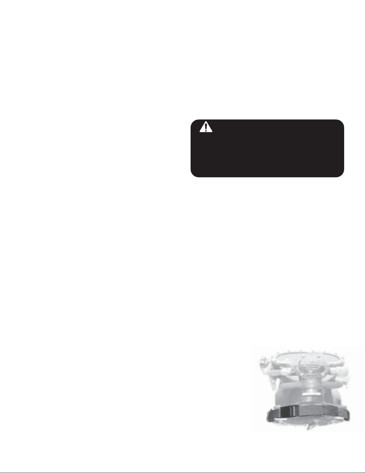
2-B DRESSINGINTOTHEMILLER HELMET
Check for proper adjustment. The Head Harness is eas-
ily adjusted by moving theAdjustment Buttons. Do not
over tighten. The Upper Mounting Washer and Screw
have three adjustment holes in the upper pad which will
change the angle of position on the head.
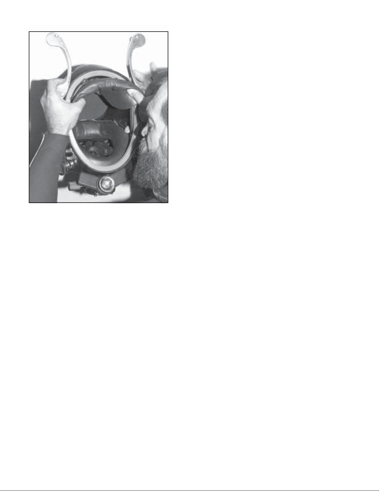
Pull Neck Ring and Neck Seal over the head with-the
Screw heads facing down. The Neck Seal should be
turned down and may be tucked into the wet suit jacket.
2-A PRE-DIVE PROCEDURE:
1. Inspect Helmet shell for any damage or loose valves
or fittings.
2. Inspect all rubber parts for wear, cracking, and proper
installation.
3. Inspect exhaust valves to see that they are free of for-
eign matter and in good condition.
4. The Helmet should be hooked up to a suitable gas
supplyand allvalves &exhausts checkedfor properfunc-
tion as follows: Open Free-flow Valve to assure suffi-
cient airflow.With Free-flow Valve closed, ascertain that
theDemand Regulatoris breathingproperly. Inspecteach
exhaust valve by opening and closing it while Free-flow
Valve is open.
5.Test radiocommunications by talking both toand from
the diver.
6. Test Non-return Check Valve for proper function with
at least one of the following :
Ist test: This test must be made with Free-flow Valve
open and the supply umbilical removed from Helmet.
Place your mouth on inlet fitting and suck while placing
tongue over orifice. The tongue should stick, due to the
vacuum created if the check valve is operating properly.
If the tongue does not stick, or air can be sucked out of
valve, there is a leak and it must be corrected before
diving.
2nd test: This test must be made with Free Flow Valve
closed and the supply umbilical removed from Helmet.
Disconnect the Demand Tube from Regulator Inlet Fit-
ting.Attempt to blow in end of tube. It should be impos-
sible if check valve works and all connections are tight.
3rd test: The Check Valve must be removed from the
Helmet and supply umbilical. Test by attempting to blow
against arrow direction. It should be impossible (no leak-
age) if valve is functioning correctly.
7.Verify emergency gas cylinder is full to rated capacity
and is properly connected to Helmet.
With the tender holding the Helmet in a convenient posi-
tion, the diver places both thumbs on the lower pad, stretch-
ing it back and open. The back of the head is inserted first
and the Helmet is then
rolleddown over theface.
TheNeck Ring isinserted
into the Helmet and the
Cam Handles are closed.
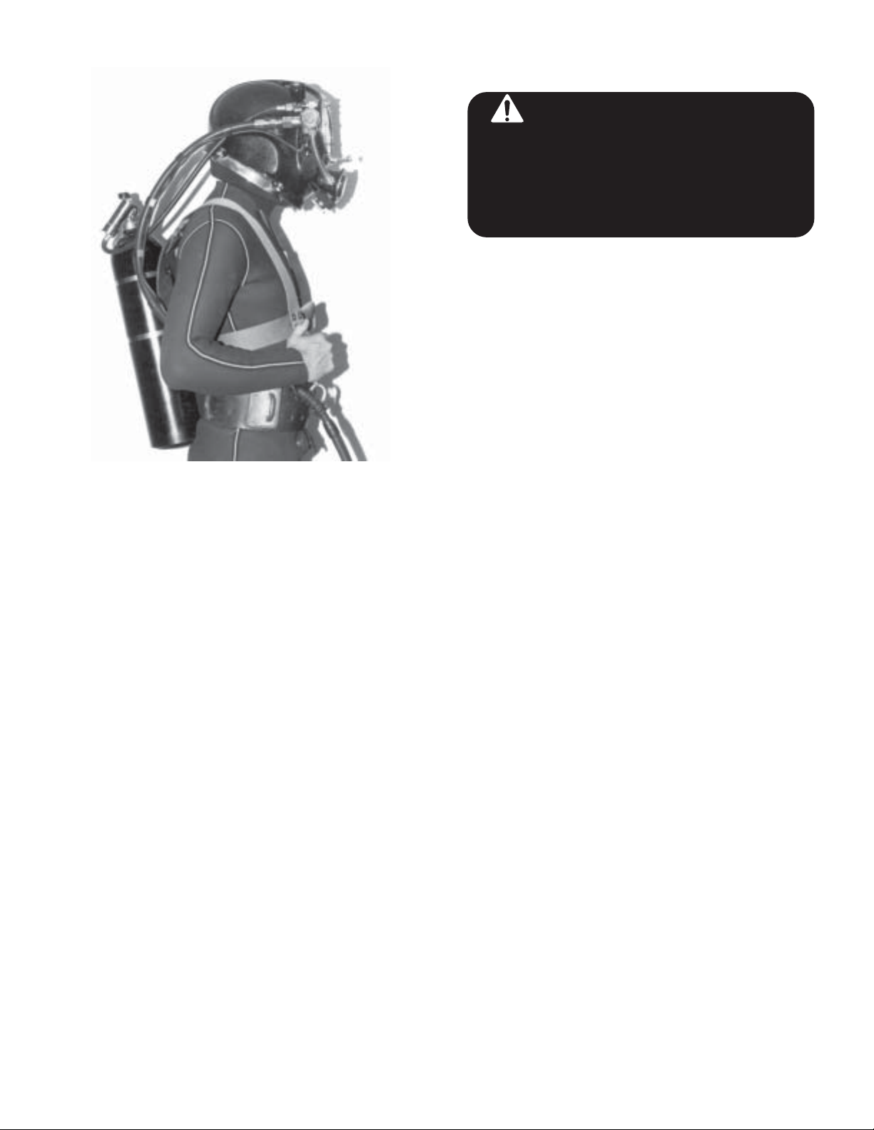
Then the buckle halves of
thepositive locking straps
are pulled forward and
snapped together, locking
the cams.

© Miller Diving All Rights Reserved Document # 030715001
9
Stretch the Head Pad (106) with your thumbs while
The entire dressing operation can be done by the diver
without assistance This should be practiced until the pro-
cedure becomes familiar
HELMET REMOVAL:
Release and open the buckle of the Positive Locking
Straps. Release the Neck Ring from the Helmet by fully
opening the Cam Handles. The Helmet can then be re-
movedby graspingthe front(near theRegulator) andpush-
ing out and up. Removal under normal conditions or in an
emergency can be accomplished in less than five seconds.
2-C OPERATING INSTRUCTIONS
It is recommended that the diver fully acquaint themselves
with all valves, components, and accessories in a training
tank or shallow water before making a working dive.
A thin film of anti-fogging solution (such as liquid dish
soap) may be applied to the inside of the Face Plate to
prevent fogging.
Thediver shouldtest radio communications,the FreeFlow
and Demand breathing systems, just before the dive.
The -Regulator Adjustment Knob should be adjusted to
prevent free flow.
The umbilical should be hooked to the diving harness with
a suitable snap. (Miller Diving Equipment manufactures a
full line of diving harness and backpacks). Do not attach
the umbilical to the weight belt.
If it is necessary to jump off a high barge or boat, the side
exhaust should be fully closed, the Regulator Exhaust par-
tially closed, and a strong Free Flow turned on. Do not
jump into the water using only the Demand System, as the
impact could force water through the exhausts. Hold on to
the Helmet securely with at least one hand when jumping.
Liberal use of Free Flow Valve will be much more com-
fortable to the diver in a hard working situation. However,
using the demand system is much better for communica-
tion purposes and is essential for economical consump-
tion if using a mixed gas breathing media.
The Helmet should be rinsed with fresh water after each
dive and stored out of sunlight with good ventilation. Store
the Neck Ring separately to allow Helmet to dry out com-
pletely.
2-D EMERGENCY PROCEDURES:
An EMERGENCYGAS SUPPLY should be used for all
diving operations. The emergency gas should correspond
to the breathing media being used for the dive. The supply
should be adequate for a safe return to the surface or div-
ing bell. This must be determined by the diver according
to depth and duration of the dive. In most emergency situ-
ations, it is normally best NOT to remove the diving Hel-
met unless absolutely necessary. Communication with sur-
face personnel may aid in rapid restoration of lost gas sup-
ply.
Several safety harness/back pack combinations are manu-
factured by Miller Diving Equipment for mounting emer-
gency gas cylinders and attaching the main umbilical to
the diver.
The gas cylinder must be equipped with a first stage regu-
lator and a hose. The first stage regulator used on the emer-
gency gas cylinder should be equipped with a pressure re-
lief valve (pop off valve), in the event the first stage regu-
lator develops a leak that could overpressure the hose lead-
ing to the Helmet.
The hose is connected to an Emergency Valve which is
installed in the Emergency Valve Elbow on Free Flow
Manifold Valve.

© Miller Diving All Rights Reserved Document # 030715001
10
Prior to the dive, the emergency cylinder valve is turned
on, pressurizing the first stage regulator and hose. The
emergency on/off valve is closed. In event of an emer-
gency (loss of main gas supply) the emergency valve is
turned on, supplying emergency gas to the Helmet. Us-
ing only the Demand Regulator will conserve the lim-
ited emergency gas supply. The diver's weight belt may
be dropped to assist in rapid ascent to the surface
The above recommendations are basic guidelines only.
Diver preference and/or employer's regulations will best
determine proper emergency procedures. Comprehen-
sive emergency training is considered absolutely neces-
sary for safe diving operations.
WATER LEAKAGE
In the event of a small amount of water entering the in-
terior of the Helmet or an emergency flooding, the clear-
ing procedure is the same. Open the Free Flow Valve
and close the Side Exhaust. This will force any water
out the lowest part of the Demand Regulator through the
Exhaust Valve.
Alternatively, the Regulator Exhaust should be closed
and the side exhaust opened with the head tilted to the
side, so Side Exhaust is lowest point in Helmet. Water is
blown out with Free Flow Valve.
It can be determined if the Rubber ExhaustValve is bro-
ken off or obstructed (open) with a foreign object, by
shutting off Free Flow and very carefully attempting to
breathe with the Demand System. If water enters, clear
it out again with the Free FlowValve. If the malfunction
continues, the dive must be terminated and the problem
corrected. Remember to inspect the diaphgram and neck
dam for damage also.
If water remains in the rear of the Helmet:
The Side exhaust should be fully closed. The Regulator
Exhaust should be partially closed, and the Free Flow
Valve lightly turned on. This will overpressure the Hel-
met and force any water out of the lowest point, the Neck
Seal. Hold securely on to the Helmet with at least one
hand while attempting to blow out any water.
NOTE: This is wet suit procedure only! Do not at-
tempt this if Helmet is mated to a dry suit.
2-E RECOMMENDED MATERIALS FOR
MAINTENANCE
SILICONE RUBBER SEALANT:
Valve bodies, the Face Plate, and fittings are sealed and
bonded to the Helmet Shell with Silicone Rubber Seal-
ant.
WET SUIT GLUE:
Rubber components are cemented to the Helmet Shell
with Wet Suit Glue. A good rubber contact cement may
be used if Wet Suit Glue is not available.
SILICONE GREASE:
Threads, moving parts, O-rings and various rubber parts
are lubricated with Silicone Grease. It should be a non-
toxic, oxygen compatible formula.
WARNING: Do not modify this
helmet. Removal, modification or
replacement of any MILLER component
with non MILLER parts will make this
helmetunsafefordiving.Useonlygenuine
MILLER replacement parts!
Diver with emergency gas supply
connected to the helmet.

© Miller Diving All Rights Reserved Document # 030715001
11
MARINE EPOXY PAINT:
The Helmet coating can be refinished or nicks and
scratches spot painted with Marine Epoxy paint. Avail-
able at yacht or boat supply shops.
TEFLON TAPE:
Fittings with tapered pipe thread (NPT) are sealed leak
tight with Teflon Tape.
BRASSO®:
All brass and bronze parts with polished finish can be kept
looking bright with Brasso®or other metal polish.

© Miller Diving All Rights Reserved Document # 030715001
12
SECTION 3
DESCRIPTIONS, MAINTENANCE,AND REPLACEMENT
3-A HELMET SHELL
DESCRIPTION:
The Helmet Shell is constructed from an approximately
1/4 inch thick, high strength, bronze alloy. The valves
and fittings are all solidly mounted, metal to metal.
MAINTENANCE:
The Helmet should be rinsed off with fresh water after
diving and stored away from the sun. Neck Ring should
be removed to allow inner condensation to evaporate.
Nicks and scratches in the Helmet coating can be spot
repaired with a marine epoxy paint.
DANGER: Never use any aerosol pro-
pelled sprays near the face port of any Miller
diving helmet. The Freon propellant used in
these aerosols can invisibly damage the Clear
polycarbonate face port and cause it to shatter
on impact from any strong blow. If the face port
failsunderwaterthehelmetwillfloodanddrown-
ing may result.
3-B FACE PLATE AND FACE RING
DESCRIPTION:
The Face Plate is fabricated from 3/16 inch, Polycar-
bonate plate, which is highly impact resistant. Small ex-
terior scratches tend to disappear under water. The Face
Plate is secured by Screws to the Helmet by a bronze
Face Ring with a molded recess for the plate.Asilicone
rubber sealant is used to bond the plate to the Helmet.
REMOVALAND REPLACEMENT:
1. Unscrew the Nose Device Knob.
2. Pull out Nose Device Rod from inside Helmet.
3. Remove the Slotted Nut and Washer.
4. Pull Oral Nasal free from Nose Device Housing .
5. Unscrew and remove Nose Device Housing from
Helmet and Face Ring.
6. Remove all Screws and pry off Face Ring
7. Remove Face Plate from Face Ring.
8. Remove old rubber sealant from Face Ring and Hel-
met by scraping with a blunt screwdriver or scraper. It is
important that these areas are free of old sealant and are
very clean.
9. To install new Face Plate, remove paper from Face
Plate and insert the new Face Plate into Face Ring.
10. Fill the gap between the side of the face plate and the
face ring with silicone.
11. Apply an 1/8" thick bead of silicone sealant com-
pletely around the edge of the face plate.
12. Place Face Ring on Helmet and attach, beginning
with Nose Device Housing. Next, insert one of the up-
per Screws, to align Face Ring. Insert all Screws, but do
nottighten until allare inplace. Excess sealantwill squirt
out on both the inside and outside of the Helmet when
Face Ring is tightened. This excess sealant can be re-
moved by allowing it to cure for about 20 minutes, then
running a toothpick around the edge, cutting the sealant.
It will then peel off easily.
13. Replace Oral Nasal, Washer, and secure with Slotted
Nut.
14. Replace Nose Device Rod and secure with Nose De-
vice Knob.
NOTE: Certain chemicals and sprays propelled by
Freon can injure and weaken the face plate material.
Do not use solvent or degreaser for cleaning. Use only
warm soapy water.

© Miller Diving All Rights Reserved Document # 030715001
13
3-C NOSE CLEARING DEVICE
DESCRIPTION:
The Nose Clearing Device aids in equalizing the sinus
and inner ears. During the diver's descent, the rod and
pad extend into the interior, where the nose may be
blockedfor equalizing.TheNose Rod issealed watertight
by two O-rings which are housed in a Packing Nut. The
rod is pushed in and out by the Nose Knob.
REMOVAL AND REPLACEMENT
1. Unscrew the Nose Device Knob.
2. Pull out Nose Device Rod from inside Helmet.
3. Remove Slotted Nut and Washer.
4. Pull Oral Nasal free from Nose Device Housing.
5. Unscrew and remove Nose Device Housing from Hel-
met and Face Ring.
6. Remove Packing Nut. Remove the two O-rings inside
the Packing Nut.
7. Before replacing the two O-rings, lubricate them with
Silicone Grease to allow the Nose Rod to slide in and out
freely. Tighten Packing Nut snugly against the Housing.
8. To replace unit, screw Nose Device Housing onto Hel-
met and Face Ring. A small amount of Silicone Sealant
should be applied to the hex and thread of the Nose Hous-
ing before its placement. Tighten Nose Housing securely.
9. Replace Oral Nasal on Nose Device Housing and se-
cure with Slotted Nut and Washer.
10. Replace Nose Rod inside Helmet and secure with
Nose Knob.
3-1) ORAL NASAL MASK
DESCRIPTION:
The Oral Nasal is attached directly to the Demand Regu-
lator. Inhaled gas passes from the Regulator through the
Oral Nasal to the diver. Exhaled exhaust gas from the
diver goes directly back through the Oral Nasal to the
Regulator and out Regulator Exhaust. The Oral Nasal
reduces dead air space to a minimum to prevent C02
buildup. Gas from Free Flow Valve while on steady flow,
passes into the Oral Nasal through the two inlet discs to
the diver and out through the Regulator Exhaust.
REMOVALAND REPLACEMENT:
1. Remove the Nose Rod and Nose Knob.
2. Remove Slotted Nut and Washer to release Oral Na-
sal from the Nose Device Housing.
3. Remove Microphone and Wire from Mask.
4. Pop the Mask out of the groove in Mount Fitting. Fit-
ting may be removed if necessary by removing the six
Screws which hold the Regulator Retainer Plate.
5. To replace Oral Nasal Mask install Mount Fitting with
O-ring trapped between Regulator and Regulator Re-
tainer Plate.
6. Install Microphone and Wire.
7. Pop the Oral Nasal tube into Fitting Groove with a
blunt screwdriver.
Pop the Oral Nasal tube into Fitting Groove with a blunt
screwdriver.
8. Push Oral Nasal onto Nose Device Housing.
9. Secure with Washer and Slotted Nut.
10. Install Nose Device Rod and secure Rod with Nose
Device Knob.

© Miller Diving All Rights Reserved Document # 030715001
14
Remove the Valve Stem and Packing from the Manifold Body.
WARNING: Never connect the main gas
supply hose from the diving station/umbilical
to the emergency valve. There is no one way
valve in the emergency valve. If this mistake is
made, any break in the supply hose could pos-
sibly result in a “squeeze”.
3-E FREEFLOW MANIFOLD
DESCRIPTION:
The Freeflow Manifold serves as an adjustable on/off
valve, supplying gas to the interior of the Helmet. Open-
ing the Freeflow Handle allows breathing gas to flow
into the Helmet interior where the Freeflow Muffler di-
rects it over the Face Plate to the diver and creates an
anti-fogging action. An angular passage within the
Freeflow Manifold allows the gas to bypass the on/off
system and flow through the Demand Tube to the De-
mand Regulator, unobstructed and independent of the
on/off valve system. Gas from either the supply umbili-
cal or from an emergency gas supply follows this pas-
sage to the Demand Regulator.
MAINTENANCE AND REPLACEMENT:
Simple maintenance may be carried out on the Teflon
Packing, Washers, Valve Stem without removing Mani-
fold Body from Helmet.
1. Remove Screw, Handle, Packing Nut. Then, unscrew
Stem and Packing.
5. Replace Teflon Packing or other worn parts.
6. To reassemble, screw Stem with Washers and Pack-
ing into Manifold Body, and secure with Packing Nut
.
7. Install the Handle on the Stem. Be sure the screw en-
gages the hole in the Stem.
8. Tighten the Packing Nut so that some resistance is felt
to rotation of Handle. Do not tighten excessively, but
the Nut must be tight enough so that no gas escapes
around Valve Stem. The Freeflow Muffler may be re-
moved from the inside of Helmet, cleaned or replaced
without difficulty. If necessary to remove the Manifold
Valve Body from the Helmet, proceed as follows:
9. The Face Plate and Face Ring must be removed for
access to Manifold Valve Nut and the small set screw
located under the faceplate. See section 3-B.
10. Remove Muffler and unscrew Manifold Nut. Back
out the set screw slightly, freeing the Manifold Body.
The Manifold Body may now be removed.
11. Remove old sealant from Helmet area and Manifold
Body.
12. Wash Manifold Body in warm soapy water, rinse and
air dry.
13. Inspect Body, Threads, and Seat for wear.
14. To reassemble, install a new O-ring on body.
15. Apply an approximately 1/8 inch layer of silicone
sealant over O-ring and base of thread area.
16. Install the Body in the Helmet. Run the Manifold
Nut in snug, then tighten the set screw against the Body.
Finish tightening the Manifold Nut.
17. Install Muffler. Be sure O-ring has not popped out of
its groove.
3-F CHECK VALVE
DESCRIPTION:
Puncture or breakage of the supply umbilical or other
surface support equipment could create a suction inside
the Helmet which could result in serious injury to the
diver. The Check Valve is used to prevent reverse flow
2. Inspect all parts for wear.
3. Wash parts in soapy water. Rinse and air dry.
4. Lubricate threads with silicone grease.

© Miller Diving All Rights Reserved Document # 030715001
15
of gas from the Helmet, thus eliminating this possibility.
The Check Valve is designed to assure a high flow rate of
gas, low noise, and a high degree of reliability. It is easy to
disassemble and inspect. The Valve is marked with an ar-
row to indicate flow direction.
WARNING: The one way valve must be
testeddaily,prior to thecommencementofdiving
operations. Failure of one way valve could cause
seriousinjuryor death. Follow the procedures for
testing the valve outlined in this manual.
WARNING: Never dive if the one way valve
is not operating properly. If the hose or breathing
gas/air fitting breaks near the surface a serious
injury could result to the diver’s lungs and/or
eyes.Inextremecasesthiscouldbefatal.Theone
way valve must be tested daily prior to the com-
mencement of diving operations.
REMOVALAND REPLACEMENT:
1. Remove Check Valve from Freeflow Manifold.
2. Use two wrenches to disassemble the two piece body.
3. Wash Valve Body and all internal parts in warm, soapy
water, rinse and air dry.
4. Inspect internal parts for wear and replace if necessary.
5. Lubricate 0-rings with silicone grease, then wipe clean
to prevent foreign particles from sticking to the internal
parts.
6. Assemble and test.
DANGER:Iftheonewayvalveortheadapter
is loosened this will allow breathing gas to leak
outofthebreathingsystem.Thiscouldalsoresult
in a loss of all pressure to the helmet, leaving the
diver with nothing to breathe.
3-G EMERGENCY VALVE ASSEMBLY
The emergency valve assembly is not built into the side
block. It is a separate component that can be removed and
replaced, or disassembled in place on the side block as-
sembly. The Emergency valve control knob is not inter-
changeable with the defogger valve control knob.
Disassembly of the Emergency Valve Assembly
Tools Required:
11/16 inch Open End Attachment on Torque Wrench
1 inch Open End Attachment on Torque Wrench
3/8 inch Slotted Flat Blade Screwdriver
8 inch Adjustable Wrench
1) Remove the lock nut, spring, and knob.
2) Undo the packing nut. When the packing nut is free
of the threads of the emergency valve body, back out the
stem until it is free of the emergency valve body.
3) Remove the packing nut, packing, and washer from
the stem.
Cleaning and Lubricating
1) Clean all the metal parts in a 50/50 dilute solution of
white vinegar/water. Rinse with fresh water. Clean all
parts. See the cleaning instructions.
2) Inspect the packing and washer for wear and replace
if necessary.
3) Inspect the stem seat for unevenness or wear and re-
place if necessary. It must also be replaced if the stem is
bent.
4) Check the seat in the emergency valve body for wear
or unevenness. Replace the body if necessary.
5) To remove the emergency valve body from the side
block the one way valve assembly must first be removed.
Reassembly of Emergency Valve Assembly
Tools Required:
11/16 inch Open End &1 inch Open End Attachments
on Torque Wrench
3/8 inch Slotted Flat Blade Screwdriver
Soft jaw vice
NOTE:
Theemergencyvalve does nothaveto be removedfrom
the side block to be rebuilt. If the valve is to be re-
moved, the one way valve should be removed first, al-
lowing the emergency valve more clearence when ro-
tating.
1) With the exception of the tapered pipe thread end of
the emergency valve body, lubricate all components with
a light coating of silicone grease.

© Miller Diving All Rights Reserved Document # 030715001
16
2) Place the new Teflon washer and new packing on the
stem. NOTE: There are two different packings and
washerssupplied inthe kit,for rebuildingboththeolder
style and the newer high flow emergency valve which
iswhatallnewMillerHelmetsare equippedwith.Match
the removed packing and washer to the new ones
supplied and discard the others.
3) Holding these components in place on the stem, screw
the stem into the emergency valve body.
4) Rotate the stem until it is seated all the way in.
5) Thread the packing nut onto the body. Run the nut in
and tighten slightly with a wrench.
6) Place the knob onto the stem and rotate the stem all
the way out, then back again. The rotation must be
smooth. If “hard spots” or unevenness are felt during
the rotation, the stem may be bent and could need re-
placement.
7) Tighten the packing nut with a wrench until moderate
resistance is felt when turning the knob.
8) Place the spring, and locknut onto the stem securing
the knob.
9)Tighten the locknut until it is flush with the knob.The
assembly is now complete and ready for testing.
10) Test the valve by attaching it to an emergency air
supply source. There must be no leakage of gas past the
stemor throughthe packingnut.Turn onthe bailoutbottle
and leave the supply on for several hours. There must be
no drop in pressure in the system if the valve is operat-
ing properly.
11) If the emergency valve had been removed from the
side block, ensure the pipe threads are clean and retape
with teflon tape. Wrap the pipe threads starting two
threads back, under tension, clockwise with 11/2wraps.
Reinstall the emergency valve in the side block then re-
install the one way valve and torque to 240 inch lbs.
DANGER:DonotallowanyexcessTeflon
tape to cover the end of the pipe thread fittings.
Loose pieces of Teflon tape can interfere with
the performance of helmet components and
mayblockthediver'sairsupply.Thiscouldlead
to death through suffocation.
WARNING: A leaking emergency valve
assembly can cause the diver to exhaust his
entire emergency air supply (bailout) without
his knowledge. This may lead the diver to mis-
takenly assume his bailout supply is available
when it is not. This could lead to panic or
drowning in an emergency. Any worn compo-
nent that causes an emergency valve to leak
must be replaced.
CAUTION/WARNING: Never connect the
main gas supply hose from the diving station/
umbilical to the emergency valve. There is no
one way valve in the emergency valve. If this
mistake is made, any break in the supply hose
could possibly result in a “squeeze”.
WARNING: Be sure the Emergency air/
gas first stage regulator is fitted with an over-
pressure relief valve. A leaky first stage can
overpressure the hose, bursting it and causing
a loss of the entire bailout supply and possible
physical injury to the diver as the hose whips
about. Do not use a high pressure hose as the
system on the helmet is not designed for high
pressure.
3-H SIDE EXHAUST
DESCRIPTION:
TheSide Exhaust consistsof theMain Bodyheld inplace
by a Retainer Plate. The Closeable Handle is secured by
a Clip Ring. The Rubber Exhaust Valve is of the mush-
room type. As a safety feature the exhaust can be fully
closed. It also serves as a buoyancy control while using
a dry suit. The primary function of the Valve is to ex-
haust gas from the main Helmet Shell when Freeflow is
used.
MAINTENANCE AND REPLACEMENT:
1. To change the Rubber Exhaust Valve it is not neces-
sary to remove the complete Side Exhaust Body from
Helmet. Remove Handle by dislodging Exhaust Clip
Ring from its retaining groove. Locate the end of the
split Exhaust Clip Ring and dislodge by poking a small
nail or sharp punch into one of the holes in the Exhaust
Body and popping it out.
2. Grasp the Rubber Exhaust Valve and pull to remove.

© Miller Diving All Rights Reserved Document # 030715001
17
Adjust Cams with a wrench and screwdriver.
Press Rubber Exhaust Valve firmly into place with
thumb. Be sure tip exits on opposite side.
3. The O-ring may be removed with a blunt screwdriver,
being careful not to damage the inner surface of the Ex-
haust Body.
4. To remove brass Exhaust Body, unscrew the six Screws
from inside the Helmet. Remove the Exhaust Retainer
Plate. Push the body out from the inside.
5. Before replacing the Exhaust Body, clean any old sili-
cone sealant from Helmet and Exhaust body.
6. Replace Body O-ring and coat base of Exhaust Body
including O-ring with silicone sealant.
7. Place Exhaust Body in hole, making sure Ports are fac-
ing up and back.
8. Replace Exhaust Retainer Plate and fasten with the six
Screws inside the Helmet. (Be certain that the O-ring has
not popped out from its groove).
9. Excess silicone sealant should be removed by letting it
cure for about 20 minutes, then run a toothpick around
edge and peel it off.
10. Lightly lubricate new inner O-ring with silicone grease
and install.
11. Lightly lubricate the tip of Rubber ExhaustValve with
siliconegrease. Insert tipin holeand pressfirmly into place
with thumb. (Be sure the tip exits on opposite side of Ex-
haust Body to lock in place).
3-I CAMS
DESCRIPTION:
The two Cam Handles lock the Neck Ring tight against
the Neoprene Gasket with four points, for an effective
water tight seal. The Cams are simple, rugged and de-
signed for quick, jam-proof operation. They are easily
adjusted with the Handle Screw and Cam Nuts.
MAINTENANCE AND REPLACEMENT
1. To remove handle, loosen Cam Lock Nut and unscrew
the Handle Screw at the rear Helmet ear and remove the
Cam.
2. To replace Cam Handle, install Cam on rear Helmet
ear in this order:
3. Place Screw through ear, from top down.
4. Position Washers, usually three, under rear ear.
5. Install Cam Nut under Washers (not tight).
6. Place Cam on bottom and fasten with Screw until snug.
7. Tighten Cam Nut against Cam. The Screw, Cam Nut,
andCam arenow locked together.The Cam Handle should
swivel freely, without up and down play, on the rear Hel-
met ear.
8. The front ear tension adjusts with Screw and Lock Nut.
NOTE:The amount of washers determines the amount of
tension on rear ear, to lock the Neck Ring in place. Three
Washers are normally used in both front and rear ear.
Proper tension is achieved when pressure is sufficient to
press Neck Ring into the Gasket and Dam approximately
1/16 of an inch.
12. Place Split Clip Ring on Handle between threads and
top.
13. Screw the Handle into the Exhaust Body, allowing 1/4
in. space between the Body and Handle top. Clip Ring
may now be forced into the retaining groove in Exhaust
Body using a blunt screwdriver. (The purpose of clip ring
is to prevent the handle from unscrewing all the way out
of the Exhaust Body).

© Miller Diving All Rights Reserved Document # 030715001
18
If it is necessary to remove the regulator:
4. Pop Oral Nasal Mask free from Fitting.
5. Remove the six Screws holding the Retainer Plate.
The Regulator may now be pulled away from Helmet.
The internal parts of the exhaust are removed and ser-
viced, same as Side Exhaust. See section 3-G.
6. The Exhaust Deflector easily pops off and on.
7. When installing Regulator on the Helmet be sure to
clean old silicone sealant from O-ring area.
8. Install new O-ring. Apply approximately 1/8" of sili-
cone sealant all around O-ring area.
9. Insert the Regulator into Helmet. Be sure Oral Nasal
Fitting and O-ring are installed on the Plate prior to as-
sembly.
10. Install Retaining Plate with six Screws. Excess seal-
ant can be picked off with a toothpick after curing 20
minutes.
11. Pop the Oral Nasal into the Mount Fitting groove
with a blunt screwdriver.
12. InstallAir Supply Tube. Snug the nuts with wrench,
but do not over tighten.
MILLER-10 REGULATOR
DESCRIPTION:
Gas enters the Inlet Seat and is held back by the Disc
and Retainer. When the diver inhales, the diaphragm
draws against the Demand Lever. This action pulls the
Disc and Retainer away from the InIet Seat, allowing
the gas to flow to the interior of the Regulator Body. Gas
passes through the Mask to the diver. The Double Spring
System work together in tandem to close the valve after
each inhalation, preventing free flow of gas into the Hel-
met. The Adjustment Knob changes the spring tension
which holds back the incoming gas supply until the diver
inhales and allows the diver to adjust the resistance to
free flow, according to the depth of the dive.
3-J DEMAND REGULATOR
GENERAL DESCRIPTION:
Miller has improved the standard Demand Regulator by
encasing the internal working parts in a heavy duty, cast
bronze housing and adding a closeable exhaust as a spe-
cial safety feature. The closeable exhaust may be used
tocontrol buoyancywhen usinga drysuit withouta valve
system. The heavy duty housing protects the Demand
Regulator parts from impact damage, thus saving the
diver many extra hours of maintenance and replacement
costs. Most important, the rugged housing helps protect
from a possible mishap due to a blow to the regulator.
The diver has the option of using free flow gas or de-
mand regulated gas, according to his needs. Demand
breathing is better for communication purposes due to
the reduction of gas noise. The Demand Regulator re-
ceives gas from the tube connected to the Free Flow
Manifold.
GENERALMAINTENANCE & REPLACEMENT:
1. Remove Regulator Cover by unscrewing six Screws.
2. Lift out Diaphragm.
3. Remove Demand Tube.
NOTE:Normalmaintenance doesnotrequire removal
of Regulator Body from Helmet.
Cover and Diaphraagm removed

© Miller Diving All Rights Reserved Document # 030715001
19
Check Free Movement and position of Lever (88).
MILLER-10 REGULATOR
INTERNAL PARTS MAINTENANCE AND RE-
PLACEMENT:
1. Unscrew Adjustment Knob as far out as possible.
2. Loosen Packing Nut with a wrench.
3. Remove the Adjustment Assembly, Shaft, Teflon
Washer, O-ring, Packing Nut, and Knob completely from
the Regulator.
4.To disassembleadjustment assembly,knock outpin with
a 3/321, punch. Be sure to rest knob against solid support
to avoid damage.
5. Tilt the Regulator and shake out the Piston, Spring set,
and Spacer.
6. Unscrew Nut from Inlet Valve. Keep Valve from rotat-
ing by inserting a small screwdriver into Inlet area.
7. Remove Spring, Washer, InletValve, Rocker Lever and
Spacer.
8.All metaland rubberparts maybe cleaned inwarm soapy
water, rinsed and air dried.
9. Inspect Diaphragm for pinholes, cracks or other dam-
age.
10. Inspect O-rings for damage.
11. Inspect Inlet Valve Seat for wear and deep groves in
the rubber disc.
12. Inspect and replace all parts necessary.
13. Lubricate O-rings and threads lightly with silicone
grease.
14. To reassemble, Slip Spring and Washer on shaft of
Disc and Retainer. Insert all three parts into Regulator
Body inlet.
15. Place Washer, Lever, Spacer, and Nut on the tip of
Shaft which now protrudes into the interior of Regulator
Body.
16. Tighten the Nut so that two threads protrude past the
nut.
17. Install Inlet Seat with O-ring.
18. Install the Piston, Spring Set, and Spacer into the ad-
justment tube of Regulator Body.
19. Install Teflon Washer, O-ring, Packing Nut, and Ad-
justment Knob onAdjustment Shaft. Line up the holes in
Knob and Shaft and tap in Pin with 3/32" punch.
20. Install the Adjustment Knob Assembly into Adjust-
ment Tube. To Adjust the Regulator, first pressurize sys-
tem with approximately 150 PSI. The Lever should be
adjusted by Nut to have no more than 1/16 in. Free move-
ment. The Lever should be even with the top of Regula-
tor Body where the Diaphragm will almost touch it. If it
is too high or too low the Lever should be bent to the
correctposition. TheAdjustment Knob should bescrewed
in to stop free flow. If free flow cannot be stopped, the
Nut is too tight.
Support the knob when driving the pin.

© Miller Diving All Rights Reserved Document # 030715001
20
3-K FACESEAL
DESCRIPTION:
TheFace Seal isfabricated fromopen cell polyfoamwith
a Neoprene skin and is glued into the Helmet with wet
suit cement. The Face Seal provides comfortable sup-
port for the diver's face. Clear communications with the
surfacepersonnel resultsfrom thediverts earsbeing sepa-
rated from the noise generated by the Freeflow demand
and exhaust systems, in front of the Face Seal.
REMOVAL AND REPLACEMENT:
1. Remove Face Seal being careful not to damage Hel-
met coating.
2. Remove as much of old glue and foam pieces as pos-
sible. Use blunt screwdriver and wire brush.
3. Position Speaker Wires allowing two to lead to rear of
Helmet and one to front.
4. Apply glue to Face Seal. Apply glue in Helmet ap-
proximately 3” wide in Face Seal area and let dry sev-
eral hours.
5. Reapply glue to Face Seal and Helmet area. Let dry
until tacky (approximately 10 minutes).
6. Beginning with forehead, attach Face Seal to Helmet
by slowly pressing down one side at a time, moving to-
ward chin, slightly stretching as you go. (It can be help-
ful to place a piece of paper under opposite side while
working to prevent premature contact).
WARNING: Wet suit glue does release
dangerous fumes which could be hazardous to
the diver.The Helmet should not be used for at
least six (6) hours after gluing.
3-L HEAD HARNESS
DESCRIPTION:
The Head Harness combines the function of a neck strap
and head pad in one adjustable unit. Moving the two
adjustment buttons in the Harness Body will fit a large
or small head. Three adjustment holes for Screw are lo-
cated in the crown of Harness Body. Moving the Screw
and Mount Washer will change the ride (angle) of the
Helmet on the diver's head.
MAINTENANCE AND REPLACEMENT
1. To remove head harness remove, Screw and Mount
Washer from crown of Helmet.
2. Remove Neck Bands by unbuttoning from Band But-
ton .
3. Install new Head Harness by attaching crown to Hel-
met with Mount Washer and Screw.
4. Button Neck Bands to Band Button.
CAUTION/WARNING: Pulling the neck
dam over the diver’s head can be difficult. The
neckdamshouldbepowderedifdry. Ifwet,the
diver should devise a system to get the seal
overhisheadwithoutexcessiveforce. Stretch-
ing (expanding) the seal and placing part way
overtheheadcanhelpreducetheforceneeded
to install the seal. Proper training is necessary
toinstallthenecksealoverthediver’sheadand
onto his neck. Although the possibility is very
remote, injury might result if this procedure is
notdoneproperly. Ifadiverdoesnotknowhow
to don the neck seal he should seek proper
instruction before proceeding.
WARNING: Never dive with a neck dam
that is too tight. A neck dam that is too tight
could cause the diver to pass out due to pres-
sure on the carotid artery in the neck.
3-M NECK RING
DESCRIPTION:
The Miller Neck Ring consists of two Mating Rings,
fifteen Screws, a chin strap and the Neoprene Neck Seal
Boot. The Neck Seal is conical shaped and is designed
to seal on the diver's neck independent of any type of
diving suit, thus the Helmet may be worn with a wet
suit, coveralls or a bathing suit. The Neck Seal may be
removed and the Neck Ring mated directly to a dry suit
for a very effective combination in cold or contaminated
water.
Table of contents
Other Miller Diving Instrument manuals