Tusa B.C.J. User manual

BUOYANCY
COMPENSATOR
JACKET
OWNER’S MANUAL
BEFORE USING ANY TUSA B.C.J.
READ THIS MANUAL COMPLETELY.
201312v4


GB
1
CONGRATULATIONS! You are now the owner of one of the many fine TUSA
products. Your new Buoyancy Compensation Jacket is built to exacting standards,
using only the highest quality materials.
Before you use your new B.C.J., please read this manual carefully. The following
warning, cautions, and notes were written to make it possible for you to enjoy your
diving experience with maximum safety.
We at TUSA want you to have many years of dependable service from your new
equipment and have many memorable and safe dives. Thank
you for purchasing one of our high quality products.
WARNING : THIS PRODUCT IS A SCUBA DIVING BUOYANCY DEVICE. THIS IS
NOT A LIFEJACKET: IT DOES NOT GUARANTEE A HEAD UP POSITION OF THE
WEARER AT THE SURFACE.
IMPORTANT NOTICE : TUSA BCJ is intended to be used down to a 50 meter (164
feet) maximum water depth and can be used in cold water with temperature below
10°C.
“MARKING”
When fully inflated in fresh water at sea-level, approximate buoyancy capacity of each
size is as follows:
Size
Lift Capacity
BCJ-5960 BCJ-5560 BCJ-2100 BC0101 BCJ-1800 BCJ-7000
XS
– – 80N (=8.2kgf) 80N (=8.2kgf) 75N (=7.7kgf) –
XS-S
190N (=19.4kgf) 130N (=13.3kgf) – – – 165N (=16.8kgf)
S
– – 100N (=10.2kgf) 100N (=10.2kgf) 90N (=9.2kgf) –
M
190N (=19.4kgf) 160N (=16.3kgf) 140N (=14.3kgf) 140N (=14.3kgf) 110N (=11.2kgf) 165N (=16.8kgf)
L
– – 170N (=17.3kgf) 170N (=17.3kgf) – 220N (=22.4kgf)
L-XL
190N (=19.4kgf) 230N (=23.5kgf) – – 145N (=14.8kgf) –
XL
– – 205N (=20.9kgf) 205N (=20.9kgf) – 220N (=22.4kgf)
15 MAX. CAPACITY : 15 Litres Tank
Diameter MAX.: ø204mm (8.0 inch)
Size
Lift Capacity
BCJ-9300 BCJ-3860 BCJ-4000 BCJ-6900 BCJ-6910 BCJ-8000 BC0501
XS
85N (=8.7kgf) 105N (=10.7kgf) 100N ( 10.2kgf) 140N (=14.3kgf) 140N (=14.3kgf) – –
XS-S
–––––––
S
105N (=10.7kgf) 125N (=12.8kgf) 130N ( 13.3kgf) 140N (=14.3kgf) 140N (=14.3kgf) 130N (=13.3kgf) –
M
125N (=12.8kgf) 155N (=15.8kgf) 160N ( 16.3kgf) 140N (=14.3kgf) 140N (=14.3kgf) 130N (=13.3kgf) 300N (=30.6kgf)
L
140N (=14.3kgf) – – 140N (=14.3kgf) 140N (=14.3kgf) 180N (=18.4kgf) 300N (=30.6kgf)
L-XL
– 195N (=19.9kgf) 190N ( 19.4kgf) – – – –
XL
– – – 180N (=18.4kgf) – 180N (=18.4kgf) 300N (=30.6kgf)
XXL
– – – – – – 300N (=30.6kgf)

2
NOTICE: The PPE (Personal Protective Equipment) mentioned in this User’s Manual
was submitted to tests for validation of the design and certified according to Art. 10 of
Directive 89/686/EEC by ITALCERT - Viale Sarca 336, 20126 Milano ITALY, Notified
body n°0426. This device is in compliance with EN 1809:1997 (PPE belonging to
category II) and EN 250:2000 (PPE belonging to category III).
The CE marking means the compliance of the device to the Basic Health and Safety
Requirements of Annex II of Directive 89/686/EEC. The number 0426 near the CE
identifies the Notified Body ITALCERT, entitled for the EC quality control system for
the final product according to Art. 11.A of Directive 89/686/EEC."
The definition of SCUBA according to EN 250:
- demand regulator, - air cylinder with cylinder valves
- carrying harness / support for air cylinder (your B.C.J.!)
- safety device/s (e.g. your Pressure gauge) , - facepiece / mouthpiece
This device is a component of your SCUBA. Remember that a SCUBA must be
composed only of CE marked components. Please read carefully the User’s Manuals
attached to all the components you intend to use to assemble your SCUBA."
Tabata cannot be considered responsible for any damage / injury to persons or things
for eventual uncompatibilities / misuse due to use of non CE marked components.

GB
3
WARNING STATEMENTS
● This information has been put together for your safety. Please read and understand
this manual completely before using your new B.C.J.
● Prior to using this product, it is required that you receive training in buoyancy
compensation from an internationally recognized educational organization.
● You should also carefully read the owner’s manual and all instructions that
accompany this product before its use.
● Misuse of this product may result in uncontrolled ascents, descents, loss of
buoyancy and control which could lead to serious injury or death.
● Please Note: This B.C.J. is not a Coast Guard approved surface flotation device for
all users and conditions.
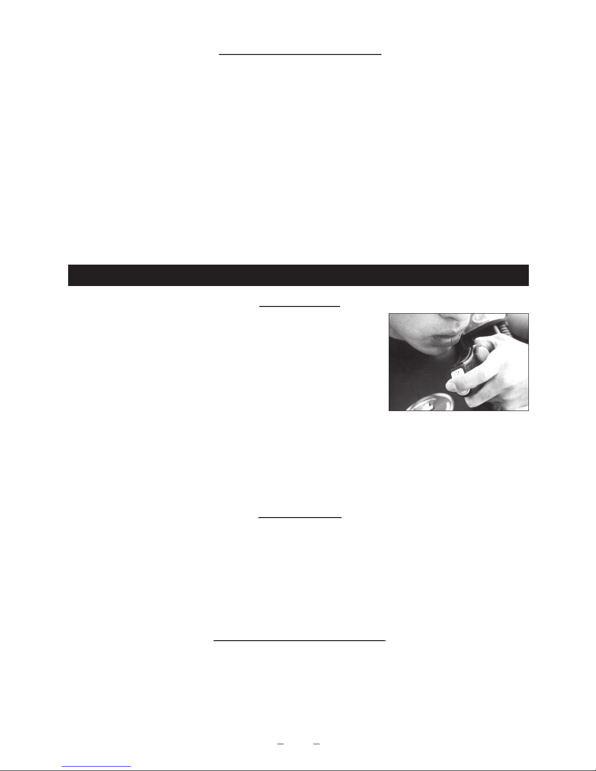
● Always inflate your B.C.J. slowly to avoid uncontrolled ascents. Rapid inflation can lead
to loss of control upon ascent which could result in air embolism, serious injury or death.
● A significant amount of practice is required in order to maintain a safe rate of ascent.
The Overpressure Valve cannot and should not be used to control or prevent
uncontrolled ascents.
● Do not add weight to the B.C.J. by placing them in the pockets, or other form of
attachment . Doing so may prevent you from easily releasing them in case of
emergency. Additionally, excess weight may reduce the buoyancy of the B.C.J. and
impair or prevent its proper operation.
● Your cummerbund and attachment straps should be adjusted for a comfortable and
proper fit. Your B.C.J. should not restrict your breathing when fully inflated. Check
all bands, straps, quick-disconnect buckle and the cummerbund for wear prior to
● Modifying your B.C.J. or using after-market accessories may prevent it from
functioning properly and could result in damage to the B.C.J. which may lead to
serious personal harm or death.
● Always examine your B.C.J. on a pre-dive, dive and post-dive basis. This will help
you identify equipment problems before they occur. Virtually all B.C.J. equipment-
related diving accidents can be prevented by following these simple warnings and
precautions. It is also strongly recommended to have your B.C.J.
checked regularly by your authorized TUSA dealer/service
center to ensure that the inflator and/or other mechanical
devices are operating properly.
● It is important to have the APA system serviced every 12 month or after 100 dives
(whichever comes first). Please see authorized dealer for overhaul.
● This equipment is designed to use standard air mixtures containing 21% oxygen
and 79% nitrogen. (the breathable air must be in compliance with EN 12021.)
Fill in your air cylinders only from certified compressors. If you have any doubt
concerning the quality of the air (e.g. smell) DON’T DIVE!
The addition of helium or other substances, or using different
mixtures may cause deterioration or corrosion of metal and rubber parts. Such
deterioration may lead to premature aging or failure. Non-standard air mixtures may
also increase the risk of fire or explosion.
● When storing, transporting in your car, or shipping the BCJ, do not have the inflator

4
hose folded. Also, do not pull on the inflator section when taking the BCJ out from a
mesh bag or the like or when carrying it around. Applying excess force to the inflator
hose, for example by folding it, twisting it, or pulling on it too hard, can cause cracks
in the hose.
● Never leave the BCJ in the passenger compartment or trunk of your car on a clear
day, exposed on a boat to direct sunlight, or in any location that might reach
extremely high temperatures over 60°C. The heat and UV rays can cause
deformation and discoloration and reduce the service life of the material the BCJ is
made from.
● Keep the BCJ away from knives, cutters, and other sharply pointed objects.
● When handling the BCJ, never place any heavy object on it, drag it around, or
handle it in any way roughly.
● The BC0501 is not a technical Buoyancy Control Jacket. Technical diving requires
specific training and equipment to ensure safety.
●BC0501 – Secure the back plate wing nuts before each dive.
●BC0501 – thoroughly clean the aluminum back plate and aluminum tank plate with
fresh water after each use to prevent possible corrosive build-up.
●BC0501 – If any corrosion appears on the aluminum back plate or aluminum tank
plate, please contact your TUSA service center before diving.
PLEASE NOTE:
This Owner’s Manual contains important safety and maintenance information. The
entire manual should be read and understood fully before using your Buoyancy
Compensator Jacket (B.C.J.). If you have any questions concerning the use or care of
your B.C.J. contact your TUSA Dealer, your diving instructor, or the nearest TUSA
Distributor.
BEFORE DIVING INSTRUCTIONS
Take the time to familiarize yourself with the function of your B.C.J. prior to use in open
water. Practice in a controlled environment, such as a pool, using all equipment that
would be used in an open water dive. Satisfy yourself fully as to its performance under
all conditions of use. Certified instruction on buoyancy control must be obtained before
using this Buoyancy Compensator Jacket. This B.C.J. is designed to make diving more
comfortable by allowing the diver to maintain neutral buoyancy. It cannot substitute for
proper swimming and diving skills. Your dive shop or diving instructor has
recommended the B.C.J. best suited for your particular diving needs.
The checks that must be performed before dive:
- Connect the QD hose to the inflator and to the pressure reducer (follow instructions
on “AIRWAY SYSTEM” para).
- Open the tank valve slowly after all the SCUBA is assembled.
- Check all the devices for inflation and deflation for correct functioning: Inflate and
deflate activating all the devices. If you feel that any of the devices do not function
properly, DON’T DIVE.

GB
5
BUOYANCY COMPENSATOR JACKET
DESIGN AND FUNCTION
Your TUSA Buoyancy Compensator Jacket is a single bag construction. With proper
care, it should give you many years of trouble-free service.
Your TUSA Buoyancy Compensator Jacket functions three ways:
1. Provides surface flotation-Your B.C.J. supplies added surface buoyancy, allowing
you to direct your energy to swimming rather than flotation.
2. Effortless ascent and descent-Increasing or decreasing air to your B.C.J. provides
positive or negative buoyancy, with rate of air increase or decrease controlling rates
of ascent/descent.
PLEASE NOTE:
Adjusting air for ascent requires practice in order to maintain a safe rate of ascent. Air
inside your B.C.J. expands as you approach the surface, causing acceleration.
Consult your certified diving instructor or diving manual for instruction regarding safe
rates of ascent and descent.
3.Allows for neutral buoyancy at various depth-When you have reached the desired
depth, adding or releasing the correct amount of air will allow you to reach neutral
buoyancy. You will neither ascend nor descend.
PLEASE NOTE:
Should repairs ever become necessary, work is to be performed only by an authorized
TUSA Dealer.
- Inflate B.C.J. until it feels firm. Let stand for 30 minutes. If the bag is not as firm as
when inflated, DON’T DIVE.
NOTE: These information are partially included in “PRE-DIVE INSPECTION” in page 9.
AIRWAY SYSTEM
Airway Systems are standard on all TUSA B.C.J.’s
Low Pressure Quick Disconnect(QD) Hose Installation
To Your Regulator
HAND-SCREW in threaded end of the QD Hose into Low Pressure Port of Regulator.
Tighten gently but firmly with a 15mm hexagonal key. The threaded connection of
the QD hose to the pressure reducer is a standardized connection 3/8" UNF. Please
refer to the User’s Manual of your regulator for identification of LP outlets.
Check your system before dive: a low pressure gauge connected to LP Ports must
not read over 1.2MPa (12bar), and under 0.8MPa (8bar) if tank is full.
It is recommended that your TUSA dealer installs your QD Hose on your regulator.
WARNING: Do not connect QD Hose to Regulator High Pressure(H.P.) Port.
Injury to diver and equipment may result.

6
(Fig. 1)
Attach the “Low
Pressure Quick
Disconnect Hose”
to the inflator plug.
(Fig. 2)
Secure the airway
together with QD
Hose to the Hock &
Loop hose retainer.
To Your B.C.J. (Fig. 1)
Connect QD Hose Inflator by pulling Quick-Disconnect Collar back with thumb and
forefinger, while pushing Hose Coupling onto Inflator Plug. Release Collar when
Coupling is engaged fully. Pull gently but firmly on Hose to check if Coupling is
securely joined to Plug. To disconnect Inflation Hose from Inflator, pull Quick-
Disconnect Collar back and disengage Coupling from Plug
Setting the low pressure hose (APA type)
Connect the plug for the
coupler for the regulator BCJ
low pressure hose, then fit in
the low pressure hose in the
groove on the side of the
inflator hose as in Figure. 3
and 4. This arranges the
hose neatly and makes it
easier to handle and makes it
easier to mount and remove
the BCJ.
(Fig. 3) (Fig. 4)
Of course, normal exhaust operations
and use of the Rapid Exhaust
Deflation by pulling the APA inflator
main unit are both possible. When
primarily using the rapid exhaust
function with the APA exhaust button,
there is also an APA inflator setting
position that uses the BCJ hose
holder to fasten with the APA exhaust
button right at hand. (Fig. 6)
Inflator setting position (APA type)
The recommended APA inflator setting position is the same as for a regular inflator.
(Fig. 5)
(Fig. 5) (Fig. 6)

GB
7
Rapid Exhaust feature is a standard item on the TUSA B.C.J.’s allowing the diver to
vent air rapidly from the B.C.J.
Procedure for activating valve is as follows:
1. Pull gently on forward Inflator Assembly to activate
Exhaust Valve. Maintain forward pressure until enough
air has been exhausted to reach desired buoyancy.
Release pressure to close valve.
(Fig. 7)
Rapid Exhaust Deflation (Fig. 7)
B.C.J. DEFLATION
Manual Inflation/Deflation button Manual Inflation/Deflation button
Auto Inflation
button
Auto Inflation
button
Manual Inflation/Deflation button
APA
deflation
button
Auto
inflation
button
APA type
(Fig. 8)
Manual Deflation
Procedure for Manual Deflation.
1. Raise Inflation/Deflation Assembly to a position nearest the surface of the water.
2. Press Manual Inflation/Deflation Button until enough air has been exhausted to
reach desired buoyancy. (Fig. 8)
3. Release pressure from button and re-position hose.
NOTE: Do not continue pressing button after all air has been exhausted from B.C.J.
Doing so may cause water to enter into inner bladder.
PLEASE NOTE:
Rapid Exhaust Valve has a pull travel limited to approximately 1/4". Pulling harder
WILL NOT increase air flow. Do not yank or jerk hard on Inflator Assembly to activate
valve, or this could lead to the damage of parts and malfunction of the system.
NOTE:
Should Rapid Exhaust Valve not operate properly, manual(oral) deflation can be
accomplished using the Manual Deflation Button.
CAUTION:
Do not press Manual(oral) Inflation/Deflation Button while exhausting air through
Rapid Exhaust Valve, as this will cause water to enter B.C.J.

8
APA inflator unit (APA type)
To take in air from the tank and obtain buoyancy, press the Auto inflation button.
Holding down this button can take in more air than necessary, so adjust the amount of
air by repeatedly pressing the button for a short while then releasing it. On the other
hand, air can be deflated from the BCJ to lower buoyancy by raising the APA inflator
main unit high in the direction of the water surface and pressing the regular Deflation
button. It is also possible to deflate rapidly by pressing the APA deflation button. Of
course, it is equipped with the Rapid Exhaust Deflation, which is a feature of TUSA
BCJs. This function “enables you to exhaust rapidly by grasping the APA inflator main
unit with one hand and just pulling in forward direction”. It is very important to practice
oral inflation method , manual deflation method and disconnecting LP hose to prepare
for any type of malfunction or emergency situation.
Over-Pressure Exhaust Valve
All TUSA B.C.J.’s are equipped with an Over Pressure Exhaust Valve. (O.P.E.V.)
This allows the B.C.J. to be automatically vented should air pressure in the inner
bladder become too great. O.P.E.V. valve will close once desired air pressure is
achieved, thus preventing damage to B.C.J. due to overexpansion.
3. Release button as you inhale air.
4. Continue inflation using Steps 1-3 until desired buoyancy is achieved.
Auto Inflation
To inflate B.C.J. slowly press Auto Inflation Button. (Fig. 8)
WARNING:
While inflating the B.C.J. it is recommended to have contact on the deflation button to
prevent an out of control ascent.
Oral Inflation
Procedure for Oral Inflation:
1. Before activating valve, purge any water that may be
trapped in mouthpiece by exhaling a small amount of
air into oral inflator opening.
2. With mouth still pressed against oral inflator opening,
press Manual Inflation/Deflation Button as you exhale.
(Fig. 9) (Fig. 9)
B.C.J. INFLATION

GB
9
CAUTIONS FOR APA INFLATOR USAGE (APA TYPE)
In case of malfunction of APA power exhaust upon emergency such as damage of
internal wire, use oral exhaust method. If the APA inflator main unit is dragged along a
surface, for example when you reach the bottom, then sand and pebbles may jam the
APA deflation button and make exhaust operation impossible. If exhaust operations do
become impossible, either use a normal exhaust operation or use the Rapid Exhaust
Deflation to exhaust. After exiting, carefully wash out the sand clogging the button with
running water.
Cummerbund Adjustment
(1) Peel off the Hook & Loop fastener of the rear end of cummerbund which has been
folded back through the appropriate slot of the waist support panel. Adjust the
length and then close the Hook & Loop fastener. (Fig. 10)
(2) If you must make a major adjustment in length, use a different slot in the waist
support panel. (Fig. 11, 12)
(Fig. 10)
(Fig. 12)(Fig. 11)
Following procedures to be performed before every dive:
1. Check the Rapid Exhaust Valve threaded fitting, and make sure they are tightened
down properly.
2. Inflate B.C.J. until it feels firm. Let stand for 30 minutes. If the bag is not as firm as
when inflated, do not use. Return B.C.J. to the nearest TUSA Dealer for inspection
and/or repair.
3. It is important to have the APA system serviced every 12 month or after 100 dives
(whichever comes first). Please see authorized dealer for overhaul.
4. BC0501 - Secure wing nuts before diving to ensure the security of single and double
tank configurations.
PRE-DIVE INSPECTION

10
Slot #1 #2 #3 #4
Shoulder Strap Adjustment (BC0501)
● The shoulder belt webbing may be adjusted to best fit each individual’s needs
(1) The webbing may be fed through the D-ring and keeper until proper length is
desired
(2) The D-ring attached to the sternum strap should be positioned at the lower edge
of the divers chest.
(3) Once the proper length is achieved, feed the webbing back through the D-ring
and keepers.
(4) Additional D-rings may be added to the webbing if desired.
Adjusting the tightness around the arm hole. (BCJ-9300, 5560, 1650, 3860, 4000)
(1) There are two adjustment slots on the waist support panel. If you feel the shoulder
strap too tight or too loose against your shoulder / arm, you can adjust by
attaching the shoulder strap into another slot.
(2) Move the metal slider to desired slot. Outer slot for wider fitting, inner slot for
tighter fitting. Simply pull on, turn parallel, and slant the metal slider . Pull the
metal slider out through the slot. Reinsert the metal slider into the new slot with
the same procedure.
(3) (Fig. 13) shows the anchor belt after adjustment. If
the metal slider comes out, the BCJ may be pulled
back by the weight of the tank and slide down. Be
sure to check that the metal slider is securely
fastened.
(Fig. 13)
(Fig. 13A)
(1) (Fig. 13A) Feed the webbing through the top
of the first slot (#1), opposite of the release.
(2) The webbing will then pass up through the #2
slot and down through the #3 slot.
Waist Belt Adjustment (BC0501)
● The waist belt buckle should be positioned on the diver’s right side webbing,
configured as a left hand release. For safety, weight belt buckles will be configured
as a right hand release.

GB
11
(3) Now pass the webbing up through the #4
(largest) slot at the end of the buckle. Feed
the webbing back underneath the buckle and
push it up through slot #1. (Fig. 13B)
(5) Excess webbing material may be cut from the
belt if desired.
1. Thread the cam buckle as shown in Figure (14 to 16).
2. Slide the backpack onto tank to desired position.
3. Cam belt should now be positioned as shown in Figure
17. Pull firmly on end of the belt until all slack has been
removed.
4. Once again check that the backpack is at desired position on tank.
5. To prevent slack of the belt while buckle is lifted, mate
the Hook and Loop fastener on the belt once in this
timing. (Fig. 18)
(Fig. 14) (Fig. 15)
THREADING AND ADJUSTING TANK BELT
(Fig. 16)
(Fig. 17)
(Fig. 18)
(Fig. 13B)

12
(Fig. 20)(Fig. 19)
6. Pull the buckle to be upright positioned as shown in Figure 19 so the belt cannot slip.
And release the Hook and Loop fastener then thread the end of belt through end slot
of buckle. (Fig. 20)
(Fig. 22)(Fig. 21)
7. Grasp belt end firmly and pull buckle to closed position. (Fig. 21) Attach belt end to
Hock & Loop fastener. (Fig. 22)
8. Check that the tank belt is securely fastened to tank. Hold tank in place in an upright
position. Grasp backpack by upper carrying handle, and try to move backpack up
and down on tank. There should be no movement, if belt moves, has not been
adequately tightened.
9. To readjust to proper tightness:
(a) Remove belt end from Hock & Loop fastener, and cam buckle.
(b) Unthread belt from end slot only of cam buckle.
(c) Repeat step 5-8 above.
10. To remove backpack from tank after a dive:
(a) Remove belt end Hock & Loop fastener, and open cam buckle.
(b) Unthread belt from end slot only of cam buckle.
(c) Slide backpack off tank.
WARNING: Proper installation and adjustment are extremely important to assure correct
performance of backpack. Improper installation on tank may allow the tank to slip out of
backpack. Loss of the tank could result in loss of buoyancy control, and/or air supply and
personal injury could result. If you have any questions about proper use for this product,
ask your diving instructor, your TUSA dealer, or your TUSA distributor.

GB
13
3. Insert the required amount of weights in the weight cartridge (possible to load up to
4kg/8.8lbs in each cartridge). (Fig. 26)
LOADING THE WEIGHTS (BCJ-8000C)
The BCJ-8000C is equipped with a weight loading system. If the weights are loaded
into the weight loading system, the underwater trim and balance of the BCJ is ideal.
Load the weights as outlined below.
The photos are for reference only. When loading weights, do so only after attaching
the BCJ onto the tank. If you attempt to load the weights beforehand, it might be
difficult to attach the tank due to the heavier load.
1. Securely hold the weight release knobs at the bottom of the pockets on the left and
right of the main unit. (Fig. 23)
2. Turn the knobs clockwise or counterclockwise to release the safety lock. Due to the
safety mechanism, there may be sections where you feel a slight pull, but the
weight cartridge can still be pulled from the mounting holder. (Fig. 24 and 25)
(Fig. 24) (Fig. 25)
(Fig. 26)
(Fig. 23)
(Fig. 27)
4. When the weights have been inserted, securely close the surface fastener and
push the weight release knob down in the position shown in the photograph. The
knob must be pushed down to this position for the safety lock to catch. (Fig. 27)
(Fig. 28)
5. Insert the weight cartridge in the mounting holder as shown in the photograph.
(Fig. 28)

14
2. Turn the knob clockwise or counterclockwise to release the safety lock on the
cartridge mounting holder (see photograph). (Fig. 31)
Due to the safety construction, you might feel a slight resistance, but continue to
pull the weight cartridge. (Fig. 32)
3. Pull the knob out further to fully release the weight
cartridge. (Fig. 33)
ON DEMAND WEIGHT RELEASE PROCEDURE (BCJ-8000C)
To release the weight cartridge when in use, follow the steps outlined below.
1. Firmly grasp the weight release knob as shown in
the photograph. (Fig. 30)
(Fig. 32)(Fig. 31)
(Fig. 30)
(Fig. 33)
6. After securely inserting the weight cartridge up to
the back of the mounting holder, close the holder
by snapping shut the buckle of the cover section
on the mounting holder.(Fig. 29)
※ Do not place any objects on the weight release knob as the buckle could slip,
causing the weight to fall out.
(Fig. 29)

GB
15
3. Place the required amount of weight in the weight cartridge. [Up to 4 kg can be
loaded in a single side.] (Fig. 37)
4. After inserting the weight, securely close the surface fastener. (Fig. 38)
5. After putting on the BCJ, insert the weight cartridge holders as shown in Fig.39. Be
sure to insert the cartridge. Having a diving buddy help will make it easier to insert
the weights.
(Fig. 38) (Fig. 39)(Fig. 37)
LOADING THE WEIGHTS (ex. BCJ-2100, 1800, 8000C)
Except for the BCJ-2100, 8000C and 1800 are equipped with a weight loading
system. The weight loading system loads weights to optimize the balance of the BCJ
in the water. Use the following procedure to load weights.
The photographs were specially made to use for the explanation. When actually
loading the weights, please do so after setting the BCJ on the tank. Loading the
weights before putting the BCJ on the tank could make it difficult to set the BCJ on the
tank because of the weight.
1. Firmly grasp the weight release knobs located under the unit’s right and left
pockets. (Fig. 34)
2. Pulling the knob will release the safety lock. For safety you will feel the weight
cartridge catch a little bit, however just continue to pull it out of the holder. (Fig. 35
and 36)
(Fig. 35) (Fig. 36)(Fig. 34)

16
6. After inserting the weight cartridges all the way into the holder, close the weight
holder’s cover buckle as shown in Fig.40 and Fig.41 until it locks closed.
7. Finally, lock the safety lock lever to complete insertion of the weights. (Fig. 42).
(Fig. 41) (Fig. 42)(Fig. 40)
unlocked locked
(indication “locked” appears)
Use the following procedure to remove the weight cartridge during use.
1. Firmly grasp the weight release knob as shown in Fig. 43.
2. Pull the knob strongly to unlock the safety lock lever. Continue to pull it to release
the mein buckle. (Fig. 44)
3. Pull the knob further and remove the weight cartridge. (Fig. 45)
* It is difficult to check the weight release knob while
diving, so make an effort to remember the position
and shape of the knob by feel.
ON DEMAND WEIGHT RELEASE PROCEDURE (ex. BCJ-2100, 1800, 8000C, BC0501)
(Fig. 43) (Fig. 44)
(Fig. 45)

GB
17
LOADING THE WEIGHTS (BCJ-1800)
The BCJ-1650 has a weight loading system. Use the following procedure to
mount weights.
* The strength of the Hook & Loop fastener is set on the condition that it be used
underwater. Therefore, you will encounter strong resistance when carrying out
setting it out of the water. Be careful not to let the fastener’s hook come in contact
with any other material since it may damage it.
1. Peel off the Hook & Loop
fastener of the cartridge
closure cover, which are on
the top of left and right
pockets. (Fig. 46)
2. Pull out the weight cartridge
from the mounting holder.
(Fig. 47)
3. Peel off the closure cover of
the weight cartridge. (Fig. 48)
4. Insert as much weight as
needed into the weight
cartridge. (Up to 4kg / 8lbs.
can be inserted into each
cartridge.) (Fig. 49)
5. After inserting the weights,
firmly close the cover.
6. Hold open the cartridge
mounting holder with one
hand and insert the weight
cartridge. (Fig. 50)
7. Push the weight cartridge all the way in, then fasten
the Hook and Loop fastener of the cartridge closure
cover. (Fig. 51)
8. Finally, close the cartridge closure cover completely.
(Fig. 52)
(Fig. 47)
(Fig. 49)
(Fig. 51)
(Fig. 46)
(Fig. 48)
(Fig. 50)
(Fig. 52)

18
ON DEMAND WEIGHT RELEASE PROCEDURE (BCJ-1800)
(Fig. 55)(Fig. 54)(Fig. 53)
1. Securely grab hold of the weight release knob as in the photograph. (Fig. 53)
2. When you pull on the knob forcefully, the Hook and Loop fastener of the cartridge
closure cover peel apart. (Fig. 54)
3. Pull on the knob further to pull out of the weight cartridge. (Fig. 55)
*“NON RELEASABLE” EXTRA POCKETS (ex. BCJ-8000C, BC0501)
(Fig. 56)
WARNING : With the B.C.J. deflated completely, and no additional weights attached,
the amount of weight in the non-releasable weight pockets MUST not cause you to
sink from the surface of the water.
ALWAYS consult with your dive instructor on the use of the non-releasable pockets
for additional weights.
ALWAYS notify your divemaster and dive buddy on the use of your non-releasable
pockets.
Two non-releasable not zippered pockets are located in the rear of
the B.C.J. (Fig. 56)
These pockets may be used for additional weights. However,
please note that these pockets CANNOT be reached by the diver
him/herself to release the weights. Please refer to the warning
listed below for further details.
This manual suits for next models
1
Table of contents
Other Tusa Diving Instrument manuals

Tusa
Tusa IQ 1203 CE Guide

Tusa
Tusa Element User manual

Tusa
Tusa element II User manual

Tusa
Tusa Geminus M-28 User manual

Tusa
Tusa ZEN AIR IQ-950 User manual

Tusa
Tusa TUL-1000 User manual

Tusa
Tusa TALIS Installation guide

Tusa
Tusa Platina IQ-600 User manual

Tusa
Tusa RS1207 User manual

Tusa
Tusa Q 1203 CE Guide

Tusa
Tusa Element II Installation guide

Tusa
Tusa DC-Solar IQ 1204 User manual

Tusa
Tusa IQ-850 DC-Sapience User manual

Tusa
Tusa ZEN User manual

Tusa
Tusa IMPREX II IQ-400 User manual

Tusa
Tusa IQ 1204 Guide

Tusa
Tusa IQ-800 User manual

Tusa
Tusa TC1 User manual

Tusa
Tusa BC0102 User manual

Tusa
Tusa RS-350 User manual