Millipore Assurance 73400-1BOX User manual

The life science business of Merck KGaA,
Darmstadt, Germany operates as
MilliporeSigma in the U.S. and Canada
Assurance®GDS Adaptor Box
Part No: 73400-1BOX
General Description
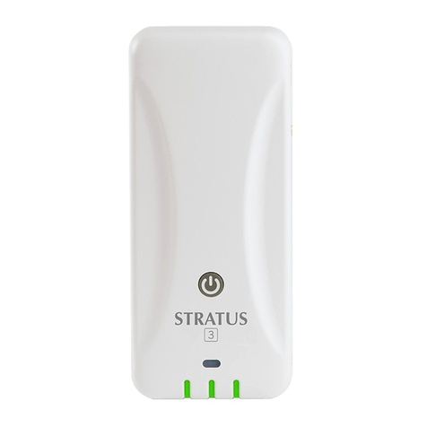
The Assurance®GDS Adaptor Box is designed to allow up to 5 Assurance®GDS Rotor-Gene®Q (RGQ) thermocyclers
to be connected to 1 laptop. In addition, the adaptor box improved connectivity between the Assurance® GDS RGQ
and laptop, preventing loss of signal during times of interruption (power loss, networking, etc.). The image below
shows the adaptor box in between an Assurance®GDS RGQ (73070BC) on the left and the Assurance®GDS RGQ
laptop (73071BC) on the right.
Included Components
The Assurance®GDS Adaptor Box contains the following:
•73401 Adaptor Box (iEi uIBX-250-BW-N3/2G-R21)
•82001-1 Ethernet Cable
•82005-1 Power Cable US
•82006-1 Power Supply (110V/220V)
Equipment / Materials Required
Other necessary regional materials not provided, but available separately include:
•82002-1 Power Cable ANZ
•82003-1 Power Cable EU
•82004-1 Power Cable UK
Other necessary materials not provided:
•If networking laptops as described in Section B below, an extra computer monitor screen to plug into the HDMI
port will be needed during setup for viewing the IP address information
•If using WiFi as described in Section B, Step 10, a regional compliant WiFi dongle will be needed during and
after setup
SetUp Procedures
There are two options:
A. No Network, 1 Assurance®GDS RGQ to 1 Laptop Interface
B. Network, Multiple Assurance®GDS RGQ to 1 Laptop Interface
Please follow the procedure per the chosen option as shown below.

Page 2 of 14
A. No Network, 1 Assurance®GDS RGQ to 1 Laptop Interface
Follow the procedure below to setup the Assurance®GDS RGQ with the Assurance®GDS Adaptor Box
when using without online networking. If networking the laptop, please go directly to Section B, below.
Note: without a network setup, the platform can only accommodate a 1:1 ratio between Assurance®GDS
RGQ-Adapter and laptop.
1. Connect the Assurance®GDS adaptor box to the Assurance®GDS RGQ with the standard USB cable
and to the controlling laptop with a standard CAT5/6 network cable. The network cable must be
plugged into port 1. [See images below]
2. Turn on laptop and navigate to the “Network Connections” panel [see images below]
Windows 10

Page 3 of 14
Windows 7
3. Select the Ethernet adaptor box; right-click on the icon and select “Properties” [see images below]
Note: Multiple icons may be present. Be sure to select the “Ethernet” icon. Windows 7 may say “Local
Area Connection” instead of “Ethernet”
Windows 10
Example of numerous icons: Select “Ethernet”
Windows 7
4. In the Ethernet Properties dialogue box, select “Internet Protocol Version 4” and then select
“properties” [see image below]
Note: there may be some additional end characters like “(TCP/Pv4)” or something similar

Page 4 of 14
5. In the “Internet Protocol Version 4 Properties” dialogue box fill in the following information for each
section [see image below], IP address: “192.168.1.10”, Subnet mask: “255.255.255.0” [SHOULD
AUOTFILL], Select “OK”
6. Start the Assurance®GDS RGQ laptop software
7. Navigate to the configuration dialog menu [see images]
Select “Setup”

Page 5 of 14
8. In the configuration dialog, enter [see image below for example]
RGQ serial number
RGQ NickName; optional
RGQ Location; optional
Base URL: fill in “http://192.168.1.20:8080/”
Interface: select “ethernet”
IP Config: select “static”
Netmask: fill in “255.255.255.0”
Leave remaining fields in default state
Save when completed
9. After the adaptor box configuration file is set up, save the configuration on a blank, standard USB
drive. [saving a backup of the “rgq.cfg” file on a computer or network is recommended]

Page 6 of 14
Note: The software will select an empty USB drive by default if one is connected to the laptop [see image
below]
10. Turn on the Assurance®GDS RGQ and Assurance®GDS adaptor box
Note: the Assurance®GDS adaptor box power buttons are designed to prevent accidental turn on/off
actions. To power on/off the adaptor box, hold the power button until button lights up [power on] or
hold power button until button light turns off [power off].
11. Insert the USB drive into each Assurance®GDS adaptor box one at a time. Ensure the respective
Assurance®GDS RGQs are connected to the Assurance®GDS adaptor boxes via USB and are turned
on.
•On recognizing the drive, the Assurance®GDS adaptor box will copy over the correct configuration
determined by the serial number of the connected Assurance®GDS RGQ.
oSeveral beep sequences will follow once the USB drive is inserted. Wait for all sequences
to finish [there will be a final two-tone chime to designate the end of all sequences]
oIf the configuration process is successful, the Assurance®GDS adaptor box will chime with
a rising three tone sequence followed by the two-tone ending sequence and the box will
become available in the laptop software [success sequence will be slow]
o[if this beep does not occur, reformat the stick to FAT or try a different stick]
oIf there is a problem with the configuration, the system will chime a three-tone decanting
sequence [failure sequence will be fast]
•The configuration sequence will generate a set of addition files on the USB drive. These are
diagnostic files that can be used for troubleshooting should any errors occur. Saving the additional
files is recommend until the user is confident the system is functioning properly. Each Assurance®
GDS adaptor box will write its configuration and errors into a file named RCB_[0123456789ab].txt
on the USB drive, where the number in the [brackets] is the primary ethernet adaptor box MAC
address. The MAC address is unique to each box.
12. Restart Assurance®GDS adaptor box and wait for connection to be made between software and box:
•User should see tab with Assurance®GDS RGQ serial number and Nickname upon restarting the
Assurance®GDS software after configuration saving.

Page 7 of 14
•When first configuring a new setup, the icon should change from the yellow “connection lost” to
the blue “empty instrument” icon when connection is established.
•Setup now complete. Corresponding instrument icons are as follows and can be used for
diagnosing connection status:
= Setup Mode Tab | Used for setting up new runs to be sent to
open instruments. Can also be used to read run files. Note: the virtual mode tab is always present.
= Empty Instrument | Instrument cleared and ready to receive
new run file. Note: instruments must be cleared before a new run can be sent to the instrument.
= Run Complete | Run has finished, and results are ready to be
read, saved, exported, etc.
= Connection Lost | Connection to the Assurance®GDS adaptor
box or Assurance®GDS RGQ has been broken and must be established before further action.
= Run in Progress | Run has been initiated and instrument is
taking readings.
= Instrument Error | problem with instrument. Seek technical
assistance.
B. Network, Multiple Assurance®GDS RGQ to 1 Laptop Interface
Follow the procedure below to setup the Assurance®GDS RGQ with the Assurance®GDS Adaptor Box
when networking your laptop [perform with the assistance of your local IT department]:
1. Connect all adaptor boxes to the user’s network. The network cable must be plugged into port 1. [See
image of hardline connection below]
•For wireless connection see Step 10 at end of Section B.
Note: User MUST select wired OR wireless connection per adapter; both wireless and wired
connections are NOT possible on a single adapter unit.
•Turn Assurance®GDS adaptor boxes on after connecting to network.
Note: the Assurance®GDS adaptor box power buttons are designed to prevent accidental turn
on/off actions. To power on/off the Assurance®GDS adaptor box, hold the power button until
button lights up [power on] or hold power button until button light turns off [power off].

Page 8 of 14
2. Turn on each adaptor box and acquire the IP addresses for each box by plugging a standard computer
monitor into each box [recommend using HDMI cable; see images below].
•If preassigning IP see Step 11 at end of Section B.
•For IT department: If you use the box headless, use the logs of your DHCP server to locate the
box IP address.
oNote: If you use DHCP, fix the address of the adaptor box on the DHCP-Server. Otherwise,
the box may change its IP over time and thus become inaccessible to the laptop software.
If not using DHCP, the IP addresses of the box will be set in Step 11. The adaptor box will
take a few moments to acquire the IP address. The Screen will show a generic IP address
upon start following a 192.168.66.1 format [see image below]. Once the network IP
address is acquired from DHCP, the screen will show the acquired IP address [see image
below]

Page 9 of 14
3. Connect all adaptors to their respective Assurance®GDS RGQ [see image below]
4. Start the Assurance®GDS RGQ laptop software
5. Navigate to the configuration dialog menu [see images]

Page 10 of 14
Select “Setup”
6. In the configuration dialog, enter…
•the IP addresses for all adaptor boxes
•the corresponding serial numbers of each Assurance®GDS RGQ [be careful to match the correct
Assurance®GDS RGQ to the correct Assurance®GDS adaptor box]
•use port 8080 (default)
•enter the IP address assigned by the network (DHCP). [if a predesignated IP address is used,
enter the static IP]
Note: the URL format of in the example below. The IP address assigned by your DHCP should always
be followed by “:8080/” or the software will not accept the input. “RGQ NickName” and “RGQ
Location” are optional.
Fill in a new Assurance®GDS adaptor box settings dialogue box for each Assurance®GDS adaptor box-
RGQ pair using the “Add” button consecutively.

Page 11 of 14
7. After all Assurance®GDS adaptor box-RGQ pairs are set up, save the configuration on a blank,
standard USB drive. [saving a backup of the “rgq.cfg” file on a computer or network is recommended]
Note: The software will select an empty USB drive by default if one is connected to the laptop [see image
below]
Note: only one file is saved no matter the number of Assurance®GDS adaptor box-RGQ pairs. All pairs are
saved within the single file [see image below].

Page 12 of 14
8. Insert the USB drive into each Assurance®GDS adaptor box one at a time. Ensure the respective
Assurance®GDS RGQs are connected to their Assurance®GDS adaptor box via USB cable and are
turned on.
•On recognizing the drive, the Assurance®GDS adaptor box will copy over the correct configuration
determined by the serial number of the connected Assurance®GDS RGQ
oSeveral beep sequences will follow once the USB drive is inserted. Wait for all sequences
to finish [there will be a final two-tone chime to designate the end of all sequences]
oIf the configuration process is successful, the Assurance®GDS adaptor box will chime with
a rising three tone sequence followed by the two-tone ending sequence and the box will
become available in the laptop software [success sequence will be slow]
o[if this beep does not occur, reformat the stick to FAT or try a different stick]
oIf there is a problem with the configuration, the system will chime a three-tone descending
sequence [failure sequence will be fast]
•The configuration sequence will generate a set of addition files on the USB drive. These are
diagnostic files that can be used for troubleshooting should any errors occur. Saving the additional
files is recommend until the user is confident the system is functioning properly. Each Assurance®
GDS adaptor box will write its configuration and errors into a file on the USB drive with
RCB_[0123456789ab].txt naming convention, where the number in the [brackets] is the primary
ethernet adaptor MAC address. The MAC address is unique to each box.
9. Restart Assurance®GDS adaptor box and wait for connection to be made between software and box:
•User should see tab with Assurance®GDS RGQ serial number and Nickname upon restarting the
Assurance®GDS software after configuration saving.
•When first configuring a new setup, the icon should change from the yellow “connection lost” to
the blue “empty instrument” icon when connection is established.
•See Section A, step 12 above for the corresponding instrument icons which can be used for
diagnosing connection status.
•Setup now complete, Steps 10 and 11 are specific to WiFi users or preassigned IP address
config discussed earlier in procedure.
10. If WiFi connections are to be used, the Assurance®GDS adaptor boxes first must be connected to
the WiFi network. Connection to the DHCP server and obtaining an IP address can only be done after
the box is connected to the WiFi network. To connect the Assurance®GDS adaptor box to WiFi:
•You must first have the EDIMAX N150 WiFi dongle model number EW-7611ULB [you MUST have
the correct model number for the WiFi to work properly. Make sure the WiFi dongle is inserted into
one of the Assurance®GDS adaptor USB ports
•Start the Assurance®GDS RGQ software [As you would in Step 5]
•Navigate to the setup dialogue box [As you would in Step 5 and Step 6]. Select the “WiFi
Configuration” tab in the dialogue box [see image below]
•Enter the WiFi network name and WiFi network password in the designated fields [see image
below]
•Save the WiFi configuration onto a blank USB drive as you will later save the Assurance®GDS
adaptor box configuration file in Step 6.
oNote: only one WiFi config file will be saved and can be used for all adaptor boxes
oNote 2: the WiFi configuration file will be named “wifi.cfg”
oCaution: the WiFi configuration file contains the network password. Make sure the file is
always secure and feel free to delete the WiFi configuration file after all boxes have stable
wireless connections. [the file can be recreated in the setup dialogue box should it ever be
needed again in the future]
oNote 3: having WiFi configuration files and Assurance®GDS adaptor box configuration files
on the USB drive at the same time is not recommend. Troubleshooting becomes more
difficult.
•Insert the USB drive containing the WiFi configuration file into each adaptor box as you would in
Step 8.
oNote: the same rising/descending tone sequences detailed in Step 5 will indicate a
successful/failed connection to the Wifi network. [successful connection to the WiFi
network can also be verified by local IT by viewing the connections to the local network]

Page 13 of 14
oCaution: The WiFi configuration step may take several minutes [up to 5-10 min] to
establish stable network connections. Wait until you are sure all tone sequences have
finished. The WiFi connection will need to be restarted by reinserting the USB drive into
the Assurance®GDS adaptor box if the USB drive is removed before a stable WiFi
connection is made [before all chime sequences are finished]
oNote 2: like the Assurance®GDS adaptor box configuration process noted in Step 8
additional files will be generated on the USB drive after WiFi configuration. The additional
files are diagnostic files that can be used for troubleshooting. Recommend saving the
diagnostic files until the user is sure the WiFi connections are stable and IP addresses are
locked.
•Once WiFi is established have local IT lock the IP address the DHCP sever assigned the
Assurance®GDS adaptor box as done in Step 5.
•Note: the boxes will need to be told to use the WiFi interface when writing the configuration file.
Select “wifi” in the “Interface” dropdown menu in the Assurance®GDS adaptor box configuration
dialog box [see Step 5 for images].
•Resume the setup steps from step 6.
11. For preassigned IP address configuration perform the following:
•Navigate to the configuration dialogue box as detailed in Step 5 and Step 6
•Fill in the standard information as detailed in step 6 with the following difference:
oUse the IP address already reserved for the Assurance®GDS adaptor box in the “Base
URL” location
oRemember to add “:8080/” to the end of the IP address
oSelect “static” from the “IP Config” drop down menu
oFill in the “Netmask” and “Gateway” information corresponding to the network the
Assurance®GDS adaptor box is connecting to “Name Server” is an optional field
•Save the configuration file as detailed in Step 7 and resume the standard setup steps.
Storage
Store the Assurance®GDS Adaptor Box in a dry location, at ambient room temperature (18–25 °C).
Precautions
Read the enclosed iEi Quick Installation Guide and Safety Instructions before connecting the Assurance®GDS
Adaptor Box to the power source.
To prevent the Assurance®GDS Adaptor Box from overheating, do not operate it in an area that exceeds the
maximum operating temperature (60 °C).

Merck KGaA
Frankfurter Strasse 250
64293 Darmstadt, Germany
© 2023 Merck KGaA, Darmstadt, Germany and/or its affiliates. All Rights Reserved. The vibrant M, Millipore and Assurance are
trademarks of Merck KGaA, Darmstadt, Germany or its affiliates. All other trademarks are the property of their respective owners.
Detailed information on trademarks is available via publicly accessible resources.
Lit. No. VM_DU13076EN Ver. 1.0
11/2023
00125122 v 1.0
Use only the power supply and power cord(s) approved for the Assurance®GDS Adaptor Box, part numbers listed
under Included Components and Equipment sections. Use of another power supply/cord type may risk fire or
explosion. Please refer to iEi for the power specifications.
Ultimate disposal of the Assurance®GDS Adaptor Box should be handled according to all national laws and
regulations.
Manufacturing Entity
iEi Integration Corp., No. 515, Shen Fu Road, Xin Zhuang Industrial Develop Zone, Shanghai, 201108, China.
Distributing Entity
BioControl Systems, Inc., 12822 SE 32nd St, Bellevue, WA 98005, USA.
BioControl Systems, Inc. is an affiliate of Merck KGaA, Darmstadt, Germany.
