Technicolor COM3000 User manual

w w w . t e c h n i c o l o r . c o m / m c s
Page 1
Technicolor COM3000
Integrator’s Manual

w w w . t e c h n i c o l o r . c o m / m c s
Page 2
Revision Record
Revision
Date
Revision Editor
Revision Description
1.1
6/7/2018
Angelo Peruch
Final draft for Distribution 6/7/2018
Contents
1Definitions.................................................................................................................................10

w w w . t e c h n i c o l o r . c o m / m c s
Page 3
2Introduction ...............................................................................................................................13
2.1 Intended Usage ............................................................................................................................... 13
3COM3000 Product Description.................................................................................................14
3.1 Additional Features......................................................................................................................... 15
4Compatibility with Previous Hardware.....................................................................................16
5Mechanical Overview................................................................................................................17
5.1 COM400 Chassis.............................................................................................................................. 17
6COM51 Card .............................................................................................................................18
6.1 COM51A .......................................................................................................................................... 19
7QAM20......................................................................................................................................20
8System Connections ..................................................................................................................21
..................................................................................................................................................................... 21
Pre-Installation..................................................................................................................................22
9Training and Support.................................................................................................................22
10 Required Tools ..........................................................................................................................22
11 Pre-Installation Site Requirements............................................................................................22
11.1 Site Survey....................................................................................................................................... 22
11.2 Distribution Networks..................................................................................................................... 25
12 Channel Lineup..........................................................................................................................25
13 External Video Sources.............................................................................................................26
14 TV Compatibility.......................................................................................................................26
15 Installation Guidelines...............................................................................................................27
16 AT&T / DIRECTV Activation..................................................................................................27
17 Getting Started...........................................................................................................................28
17.1 Assembly ......................................................................................................................................... 28
17.2 Setting up Multiple Chassis............................................................................................................. 29
17.3 Chassis Dipswitch ............................................................................................................................ 29
17.4 Chassis Dipswitch Settings .............................................................................................................. 30
18 System Power Up ......................................................................................................................30
18.1 System startup LED Behavior .......................................................................................................... 30
Boot up........................................................................................................................................................ 31
18.2 LED Behavior after Boot up............................................................................................................. 32
19 COM400 Chassis.......................................................................................................................33

w w w . t e c h n i c o l o r . c o m / m c s
Page 4
19.1 Accessing the COM400 User interface............................................................................................ 33
19.2 Setting a Password .......................................................................................................................... 33
IGMP Activation .......................................................................................................................................... 34
19.3 IGMP Port Settings .......................................................................................................................... 34
19.4 Save Changes to Startup Configuration .......................................................................................... 34
19.5 COM400 Software Version.............................................................................................................. 35
19.6 COM400 Software Update.............................................................................................................. 35
20 The COM3000 Web Interface...................................................................................................36
20.1 User Passwords ............................................................................................................................... 37
21 COM51 Tuner Licensing...........................................................................................................38
22 Overview Page...........................................................................................................................40
22.1 QAM Summary................................................................................................................................ 41
22.2 Display Options ............................................................................................................................... 41
22.3 Channel Tuning Options.................................................................................................................. 42
23 Discover Page............................................................................................................................45
23.1 Explanation of Discover Page Fields................................................................................................ 46
24 Advanced Edit ...........................................................................................................................48
24.1 The Basic Channel Tune Screen....................................................................................................... 48
24.2 Advanced Tune................................................................................................................................ 49
24.3 Informational Status........................................................................................................................ 53
24.4 COM51 LED Control Feature ........................................................................................................... 55
24.5 COM51 CAM Log Data..................................................................................................................... 56
24.6 COM51 Software Reset ................................................................................................................... 57
24.7 COM51 File Transfer Utility............................................................................................................. 57
24.8 COM51 User Configuration Options ............................................................................................... 58
24.9 COM51 “Direct Tune” Feature........................................................................................................ 61
24.10 Remote Access Feature............................................................................................................... 61
24.11 Using the VidPlay Feature ........................................................................................................... 62
24.12 Setup for Vidplay.exe .................................................................................................................. 62
24.13 Using the COM51 “Simulcrypt” Feature ..................................................................................... 64
24.14 Displaying COM3000 Status ........................................................................................................ 64
25 Pairing Info................................................................................................................................65

w w w . t e c h n i c o l o r . c o m / m c s
Page 5
26 Tune All.....................................................................................................................................69
27 Help ...........................................................................................................................................71
28 SysInfo.......................................................................................................................................71
29 HealthInfo..................................................................................................................................72
30 EPG............................................................................................................................................73
31 Syslog ........................................................................................................................................74
32 EPG Overview...........................................................................................................................75
32.1 Guide.XML Overview....................................................................................................................... 77
32.2 Getting Started with EPG ................................................................................................................ 78
32.3 EPG Customization and Channel Mapping...................................................................................... 81
32.4 EPG editing ...................................................................................................................................... 81
32.5 Logo Creation and Upload............................................................................................................... 82
33 Welcome Screen........................................................................................................................83
33.1 Welcome Screen Image Creation.................................................................................................... 83
33.2 Uploading Welcome Screens to COM3000..................................................................................... 86
33.3 Adding Welcome Screens to Guide Data ........................................................................................ 87
33.4 Disabling Welcome Screens ............................................................................................................ 87
34 QAM20......................................................................................................................................88
34.1 Accessing the QAM Page................................................................................................................. 88
34.2 Checking Software Version and License Count............................................................................... 89
34.3 Setting QAM Output Channels........................................................................................................ 89
34.4 Setting Unique RF output to a QAM ............................................................................................... 92
34.5 Setting Unique outputs to a group of QAMs .................................................................................. 93
35 Troubleshooting.........................................................................................................................94
35.1 Software Version............................................................................................................................. 94
35.2 Verify RF .......................................................................................................................................... 94
35.3 COM51 Reset Button ...................................................................................................................... 94
35.4 Troubleshooting Common Problems .............................................................................................. 95
35.5 Features and Licensing.................................................................................................................... 95
36 Preventing Pro:Idiom Key Loss ................................................................................................96
37 Simultaneous QAM and Multicast IP Output............................................................................96
38 Syslog Server Setup...................................................................................................................98
39 Open Software Notification.....................................................................................................101

w w w . t e c h n i c o l o r . c o m / m c s
Page 6

w w w . t e c h n i c o l o r . c o m / m c s
Page 7
Table of Figures
FIGURE 1-COM3000........................................................................................................................ 14
FIGURE 2-COMPATIBILITY MATRIX.................................................................................................. 16
FIGURE 3COM400 CHASSIS.............................................................................................................. 17
FIGURE 4-COM51 CARD.................................................................................................................. 18
FIGURE 5-QAM20............................................................................................................................ 20
FIGURE 6-COM51 SYSTEM DIAGRAM.............................................................................................. 21
FIGURE 7-INSTALLATION OF THE QAM20 AND COM51.................................................................. 28
FIGURE 8–COM400 DIPSWITCH ACCESS PANEL.............................................................................. 29
FIGURE 9-CHASSIS ID DIPSWITCH.................................................................................................... 29
FIGURE 10 -LED BEHAVIOR AT BOOT UP......................................................................................... 31
FIGURE 11 -OPERATIONAL LED BEHAVIOR...................................................................................... 32
FIGURE 12 -ETHERNET SWITCH INTERFACE ...................................................................................... 33
FIGURE 13 -NETWORK SWITCH PASSWORD....................................................................................... 33
FIGURE 14 -IGMP SNOOPING SETTINGS ........................................................................................... 34
FIGURE 15-SAVE START-UP CONFIGURATION ................................................................................... 34
FIGURE 16 -COM400 SOFTWARE VERSION ...................................................................................... 35
FIGURE 17 –COM400 SOFTWARE UPGRADE .................................................................................... 35
FIGURE 18 -COM3000 USER INTERFACE INTRODUCTION PAGE ....................................................... 36
FIGURE 19 PASSWORD CHALLENGE................................................................................................... 37
FIGURE 20 -LOCK SCREEN ................................................................................................................ 37
FIGURE 21 -SYSINFO PAGE TUNER COUNT ....................................................................................... 38
FIGURE 22 -COM51 TUNER LICENSING............................................................................................ 38
FIGURE 23 -COM3000 OVERVIEW PAGE.......................................................................................... 40
FIGURE 24 -QAM SUMMARY............................................................................................................ 41
FIGURE 25 –ENCRYPTION SETTINGS ................................................................................................. 42
FIGURE 26 -CHANNEL SELECTION DROP DOWN................................................................................ 43
FIGURE 27 -OUTPUT MODE............................................................................................................... 43
FIGURE 28 -MAJOR/MINOR CH OR IP AND PORT SETTINGS............................................................... 43
FIGURE 29 -BITRATE DISPLAY .......................................................................................................... 44
FIGURE 30 -SNR AND SIGNAL STRENGTH......................................................................................... 44
FIGURE 31 -COM51 DISCOVER PAGE............................................................................................... 45
FIGURE 32 -COM51 BASIC TUNE SCREEN........................................................................................ 48

w w w . t e c h n i c o l o r . c o m / m c s
Page 8
FIGURE 33 -ADVANCED TUNE SCREEN ............................................................................................. 49
FIGURE 34 -"INFO"SECTION OF THE ADVANCED EDIT PAGE ............................................................ 53
FIGURE 35 -NETWORK ID AND FREQUENCY INDEX........................................................................... 54
FIGURE 36 -LED CONTROL............................................................................................................... 55
FIGURE 37 -CAM LOG INTERFACE.................................................................................................... 56
FIGURE 38 -CAM LOG REPORT.......................................................................................................... 56
FIGURE 39 -RESET INTERFACE .......................................................................................................... 57
FIGURE 40 -FILE TRANSFER INTERFACE............................................................................................ 57
FIGURE 41 -USER CONFIG INTERFACE............................................................................................... 58
FIGURE 42 -DIRECT TUNE INTERFACE.............................................................................................. 61
FIGURE 43 -REMOTE ACCESS FEATURE ............................................................................................ 61
FIGURE 44 -VID PLAY ....................................................................................................................... 62
FIGURE 45 -COM3000 PAIRING INFO PAGE...................................................................................... 65
FIGURE 46 -COM46 MULTI CARD UPGRADE.................................................................................... 67
FIGURE 47 -COM51 TUNE ALL......................................................................................................... 69
FIGURE 48 -HELP TAB....................................................................................................................... 71
FIGURE 49 -COM51 SYS INFO PAGE................................................................................................. 71
FIGURE 50 -COM3000 HEALTH INFO PAGE...................................................................................... 72
FIGURE 51 -SYSLOG EXAMPLE.......................................................................................................... 74
FIGURE 52 -SYSINFO EPG................................................................................................................. 75
FIGURE 53 -IPG SETUP PAGE............................................................................................................ 77
FIGURE 54 -COM3000 EPG PAGE.................................................................................................... 78
FIGURE 55- COM51 EPG LOAD ........................................................................................................ 80
FIGURE 56 -EPG CHANNEL............................................................................................................... 81
FIGURE 57 -EPG LOGO CREATION.................................................................................................... 82
FIGURE 58 -GUIDE CHANNEL WITH CUSTOM LOGO .......................................................................... 82
FIGURE 59 WELCOME PAGE POWERPOINT SLIDE .............................................................................. 83
FIGURE 60 -WELCOME SCREEN IMAGE CREATION............................................................................ 83
FIGURE 61 -WELCOME SCREEN SETTINGS USING MICROSOFT PAINT ............................................... 85
FIGURE 62 -CORRECTLY SIZED WELCOME SCREEN IMAGE............................................................... 85
FIGURE 63 UPLOAD FILE TO COM51 TFTP....................................................................................... 86
FIGURE 64 -UPLOAD WELCOME SCREEN IMAGE TO EPG.................................................................. 86
FIGURE 65 -ADDING WELCOME SCREEN TO EPG AND PSIP............................................................. 87

w w w . t e c h n i c o l o r . c o m / m c s
Page 9
FIGURE 66 -VERIFY WELCOME SCREEN IS STREAMING ..................................................................... 87
FIGURE 67 -QAM SUMMARY HYPERLINK......................................................................................... 88
FIGURE 68 -QAM TAB IP ENTRY ...................................................................................................... 88
FIGURE 69 -QAM SOFTWARE AND LICENSE COUNT......................................................................... 89
FIGURE 70 -SETTING QAM OUTPUTS ............................................................................................... 89
FIGURE 71 QAM TABLE .................................................................................................................... 90
FIGURE 72 -QAM TABLE................................................................................................................... 91
FIGURE 73 -CHANGING A SINGLE QAM OUTPUT.............................................................................. 92
FIGURE 74 -INDIVIDUAL QAM OUTPUT CHANGE ............................................................................. 92
FIGURE 75 -CHANGING OUTPUTS CHANNELS ON A GROUP OF QAMS.............................................. 93
FIGURE 76 -QAM GROUP OUTPUTS.................................................................................................. 93
FIGURE 77 -COM51 RESET............................................................................................................... 95

w w w . t e c h n i c o l o r . c o m / m c s
Page 10
1Definitions
Term
Definition
Admin PC
A PC is required for initial setup and configuration. It is highly recommended to set up
remote access to the COM3000 system for monitoring and maintenance post installation.
This can be accomplished via several methods:
A PC on site, connected to the internet running Team Viewer or a similar remote desktop
program. PC will need to be on the same IP subnet as the COM3000 system
VPN router set up for remote access via a Virtual Private Network
ATSC
Advanced Television Systems Committee. An international organization developing
voluntary standards for digital television. Typically used to describe terrestrial off air
broadcast TV standards. ATSC Tuner describes a TV capable of receiving digital off-air
broadcasts.
http://atsc.org/
ATSC-8
This is a device previously provided by Technicolor to provide ATSC off air television signals
to the COM3000. It is configured and controlled through the COM3000 web interface.
Depending on configuration it can deliver 8 program channels or 8 complete ATSC8
broadcasts including all sub channels in the carrier.
COM3000 System
This describes the Technicolor system consisting of a COM400 chassis, COM51 cards and
QAM 6 modulators. Replaced previous product COM1000
COM400 Chassis
Chassis component of the COM3000 System. Replaced previous product version COM200
COM51 and COM51-
FLX Cards
Tuner cards for the COM3000 system. Replaced previous product version COM46 /
Com46A.
COM3000
This describes the Technicolor system consisting of a COM400 chassis, COM51 cards and
QAM 20 modulators. Replaced previous product COM2000
COM400 Chassis
This device houses the COM51 and QAM 20 components in a COM3000 system. All
video traffic is routed through the two 10 Gigabit and two 1 Gigabit Ethernet (GbE) ports
on the front of the chassis and to the QAM20 slots. System management and control
can be done by connecting a computer to any of the ethernet ports on the front panel.
Replaced previous product version COM400
COM51
The bulk of this manual is dedicated to these cards. They are the means by which the
property will be able to receive the desired television programming for their network and
control the entire COM3000 system. Replaced previous product version 46
DSWiM 30
AT&T / DIRECTV SWM multiswitch, 26 tuner capacity, 13 tuners per output. One DSWiM
30 will provide signal to a COM51 card when tuning more than 8 channels
EAS
Emergency Alert Systems can be interfaced with the COM3000 to stream emergency
notifications to all channels. Similar to this a local message can be created and played via a
PC and VLC or a ZyCast Media Server.
https://www.fcc.gov/encyclopedia/emergency-alert-system-eas
Edge QAM
In a typical installation, the COM51 cards will be configured to stream to a QAM20
modulator.

w w w . t e c h n i c o l o r . c o m / m c s
Page 11
GIGe
Gigabit Ethernet High speed Ethernet standard for transmitting data at one gigabit per
second. All switches in the GIGe (video) network must be rated to pass this level of traffic.
IGMP
Internet Group Management Protocol. Used by Ethernet Switches and end devices to
manage multicast video on IP networks.
HD
High Definition
Hot-swappable
The unit or device this term describes may be added to, removed from, or replaced
within the system it is a part of without powering anything down.
Media Server
A media server converts video and audio from HDMI or Composite video and creates an
IP stream that can be modulated on the RF network via the QAM 20. There are several
manufacturers of Media servers that are compatible with the COM3000, contact you
Distributor.
MPEG
Moving Pictures Experts Group - A working group of ISO/IEC with the mission to develop
standards for coded representation of digital audio and video and related data.
Most commercial and some residential TVs support MPEG4 standards. All AT&T /
DIRECTV HD signals are MPEG4 contained in a MPEG2 transport stream. Many residential
and some older commercial TVs will only support MPEG2 signals and will require
transcription from MPEG4 to MPEG2, or the use of a setback box like the Technicolor
DCI401MCS.
http://mpeg.chiariglione.org/
PC/VLC
The COM3000 can accept streaming video from a networked PC running VLC, an open
source video software.
http://www.videolan.org/vlc/index.html
PID
Packet Identification
Pro:Idiom
Pro:Idiom is an industry accepted hardware based digital rights management encryption
technology for video signals broadcast in commercial establishments such as hotels,
dormitories and hospitals. All major programmers have accepted Pro:Idiom as an
encryption method to secure programming. Only televisions or set-back boxes with built
in Pro:Idiom encryption system decoders will be able to decrypt the signal.
http://www.zenith.com/wp-content/uploads/2013/05/ProIdiom_Overview_2010-10-
08.pdf
Pro:Idiom Mobile
Pro:Idiom Mobile is a software based Digital Rights Management (DRM) used to
encrypt programming between audio /video headends and end-user devices. It is
designed and licensed by Zenith Electronics.
https://www.zenith.com/wp-
content/uploads/2013/05/ProIdiom_Overview_2010-10-08.pdf
Property
Distribution
Network
This network, set up and maintained by the system operator or property owner,
distributes television signals via RF or IP technology. Traditional analog RF plants often
are in need of repairs and upgrades before they will pass digital HD programming. RF
levels and signal to noise ratios (Modulation Error Rate) should be tested to industry

w w w . t e c h n i c o l o r . c o m / m c s
Page 12
standards. IP systems require technicians proficient in IP switch configurations,
specifically multicast networks utilizing Internet Group Management Protocols (IGMP).
PSIP
Program and System Information Protocol. Signals included in a digital TV signal that
instruct the TV to tune to a specific channel. For example an off-air channel may be
broadcast on UHF ch 38 but the station call letters are ch 7. PSIP data instructs the TV to
look for ch 7 on UHF38. PSIP data also includes current and future programming
information.
http://www.atscforum.org/
QAM20 Cards
A board that installs in the upper left side of a COM400 Chassis. It converts the COM51’s
IP-packetized streams to QAM-modulated RF for distribution throughout a property. The
board provides up to 16 QAM channels and is software upgradeable in groups of two
QAMS for a maximum of 48 QAM channels.
Satellite
Distribution
Network
This network consists of the dish, LNB and associated equipment necessary to provide
KA/KU band satellite signals to the COM3000. The COM3000 requires a SWiM 8 signal to
each card. It is assumed that installation technicians have adequate expertise and proper
test equipment required to install the distribution system to AT&T / DIRECTV
specifications.
SD
Standard Definition
SWiM Switch
Single Wire Multi-switch –A AT&T / DIRECTV module used for distribution of satellite
signals. Available models support 8,16, of 32 tuners.
SWQAM2
The SWQAM2 is a software key that will enable 2 QAM channels per key on a QAM20
card. By pruchasing 3 SWQAM2 keys a QAM20 can be expanded to 12 QAM channels.
System
Integrator
The person or company that performs the onsite installation.
System
Operator
The company or organization that typically holds the “right of entry” and is responsible
for installation and all onsite support on a daily basis.
Transcryption
The process by which the COM 1000 system converts content streaming from AT&T /
DIRECTV ’s conditional access system to Pro:Idiom encrypted video.

w w w . t e c h n i c o l o r . c o m / m c s
Page 13
2Introduction
This document describes the Technicolor COM3000 System and related configuration procedures.
➢COM51 user interface, and descriptions of all system processes.
➢Common troubleshooting.
➢It is recommended that you read through the entirety of the manual before working with the
system, as it contains some important pointers that may come in handy during setup and
maintenance.
2.1 Intended Usage
COMMERCIAL USE This product is designed to go into areas that are not accessible to the public
at large and are not for home use. Technicolor COM3000 Products provide Head-End systems for
distribution solutions for the AT&T / DIRECTV Commercial and Lodging and Institutions (L&I)
markets
➢Satellite to QAM and/or IP distribution
➢DRM Protected High Definition Content
➢Pro:Idiom Encryption by default
➢Remote Management and Monitoring
➢Automatic Software Upgrades via Technicolor Server
.

w w w . t e c h n i c o l o r . c o m / m c s
Page 14
3COM3000 Product Description
The COM3000 is the next evolution of the Technicolor Multiclient Solution product line. It builds
on the successful COM2000 system with additions of several new features.
A COM3000 system consists of the following three components:
➢COM400 chassis
➢COM51or COM51A tuner cards (maximum of 6 per chassis)
➢QAM20 modulator (maximum of 2 per chassis)
Configured with 6 COM51 receivers and one QAM20 a COM3000 can tune up to 138 AT&T /
DIRECTV channels.
➢Each COM51 card can receive up to 23 AT&T / DIRECTV channels.
➢COM51 cards will be incrementally licensed to tune between 8 (base package) and 23 channels in
increments of one channels per software upgrade.
➢QAM20 is capable of 48 QAM channel outputs incrementally licensed from 16 (base package) to 48
QAM channels in groups of 2 channels per software upgrade.
➢The channels are routed to an internal QAM20 modulator for RF output. In addition to the RF
output the COM51 chassis provides two 10 gigabit and two 1 gigabit ethernet ports.
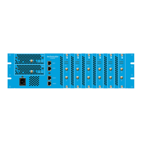
The COM3000 system is shown below in Figure 1.
Figure 1 - COM3000
➢The original AT&T / DIRECTV broadcast video encoding format is preserved, and the output
transport stream is encrypted with the Pro:Idiom digital rights management (DRM).
➢Multiple COM400 chassis can be “stacked” to provide more than 138 output channels. Up to 16
chassis can be connected in the same system.
QAM 20s
COM51
COM 400 Chassis

w w w . t e c h n i c o l o r . c o m / m c s
Page 15
➢The COM51 receiver cards are controlled and managed via an Ethernet connection within the
COM400 chassis.
oThe COM51 card includes a built-in web interface and can be configured using a web
browser.
oTo view high definition video from the COM3000 a TV or set top box equipped with
Pro:Idiom decryption technology must be used.
oStandard definition channels may be distributed in-the-clear.
3.1 Additional Features
In addition to high quality AT&T / DIRECTV programming, the COM3000 system offers
additional powerful features:
➢Optional Mediatune software upgrade offers switched matrix control capabilities for public space
environments.
➢Internal “home screen” channels can be configured to stream static image message screens direct
from the COM3000 system. No additional equipment required.
➢Vid Play utilizes a free program developed by Technicolor that will stream a MPEG2 transport
stream file from a low-cost PC (not provided) to the Technicolor QAM20 modulator for locally
originated video programming.
➢External content sources such as outboard transcoders and video encoders can be streamed to the
Technicolor QAM20 Modulator.
➢An electronic program guide that is fully customizable to system channel lineup and local
programming. PSIP data will pass to televisions and “map” the channels without intervention. (PSIP
interpretation is TV dependent, not all TVs respond to PSIP in the same manner. Test the TVs
before installing.
➢Guide.XML works in conjunction with Technicolor set back boxes to provide an interactive program
guide.
➢Interfaces with Emergency Alert Systems (EAS). Capable of sending locally originated streams to all
video channels for site specific emergency broadcast. (Only available on systems utilizing the
Technicolor QAM20 modulator).
➢Low power consumption. Typically, a fully loaded chassis draws <300 watts.

w w w . t e c h n i c o l o r . c o m / m c s
Page 16
4Compatibility with Previous Hardware
As shown in Figure 2 the COM400 chassis will support COM46 cards but not QAM6.
➢COM51 Cards will work in COM360 Chassis
oLimited to QAM6 capabilities
▪72 QAM channels
▪83 IP channels
oLimited to 1 Gigabit total IP output
Figure 2 - Compatibility Matrix

w w w . t e c h n i c o l o r . c o m / m c s
Page 17
5Mechanical Overview
The following sections contain a brief overview of the devices that you will be interacting with
along with the associated hardware. The intent is to give you a working knowledge of how the
system operates under normal circumstances.
5.1 COM400 Chassis
Figure 3 below is a front and rear view of the COM400 chassis.
Figure 3 COM400 Chassis
➢Requires 3 RU rack space
➢MTFB (Mean Time Before Failure) >43,800 hours (five years)
➢Chassis number assigned via dipswitch below top panel access panel.
➢Ventilation flows from front air vents to rear exhaust fans. Maintain adequate space for free air
flow through system
➢Chassis has slots to accept six COM51 and two QAM20 cards
➢COM51 and QAM20 cards are assigned default IP addresses per location in chassis and chassis
number.
➢10 Gigabit backplane Ethernet
➢10 Gigabit Ethernet switch configurable for Multicast Filtering, IGMPv2 Snooping
Equipped with 4 ethernet ports:
➢Two 10 gigabit ports
➢Two 1 gigabit ports
➢All ports support auto-negotiate per IEEE802.3-2015 specification. (Any Network interface device
will connect to any port).

w w w . t e c h n i c o l o r . c o m / m c s
Page 18
6COM51 Card
The COM51 card, shown in
below, is a customized AT&T / DIRECTV receiver with a built-in smart card and has been
specifically designed to meet the unique requirements of the Lodging and Hospitality markets.
➢The COM51 base configuration can receive up to 8 HD or SD AT&T / DIRECTV channels. Optional
software upgrades increase the capacity to 23 channels.
➢The COM51 removes the NDS conditional access encryption and adds Pro: Idiom content
protection DRM.
➢The output from the card is delivered to a QAM20 modulator or chassis ethernet connections via
the COM400 chassis’ internal 10 gigabit Ethernet network.
➢Web server user interface
➢Software upgradable to 23 tuners in one tuner increments
➢Requires a DSWiM input to both inputs for full 23 channel configuration (one
DSWiM30 per COM51 card.
➢SWIM input to input one supports 8 tuners
➢Configurations of more than 8 tuners requires an additional SWiM channel to the
second input.
➢Hot-swappable
➢Recessed reset button
➢LED indicators
oSee Section 18
➢Compatible with legacy COM360 chassis and QAM6 modulators
➢Manual software updates via internal TFTP server.
➢Queries Technicolor update server for software updates at bootup and at daily
intervals, downloads and installs software automatically.
oServer will instruct COM51 to complete update at a prespecified time in early
AM hours.
➢REST monitoring to AT&T/DIRECTV server is enabled as default.
➢REST Monitoring and software query can be disabled via software license.
➢Dual IP allows for local management via the default IP and will allow DHCP address
assignment for COM51.
Figure 4 - COM51 Card

w w w . t e c h n i c o l o r . c o m / m c s
Page 19
6.1 COM51A
COM51A is a specially configured COM51 card which works only with the Technicolor NTSC-8
analog modulator.
➢It will not stream signal to a QAM or ethernet port.
➢Only the NTSC-8 will receive data from a COM51A. The unit is software upgradable to a standard
COM51 for upgrade purposes.

w w w . t e c h n i c o l o r . c o m / m c s
Page 20
7QAM20
Figure 5 - QAM20
The QAM20, shown above in Figure 5 is an Edge QAM256 modulator capable of outputting up to
48 QAM channels.
➢QAM20 ships from the factory authorized for 16 QAM channels. The unit is upgradable in 2 QAM
increments via optional software license (SWQAM@) to a maximum of 48 QAM output channels.
➢Depending on DIRECTV channel bit rate each QAM channel may support up to three HD or 8 SD
program channels.
➢Accepts IP input from:
oCOM51 Card
oCOM46 Card
oExternal MPEG2 transport stream (.TS)
➢Each QAM is individually agile and able to output any channel in a 128-channel range
oLow range - channels 1-128
oHigh range –channels 26-158
➢New User interface makes configuration easier than the QAM6 in COM2000.
➢QAM Licensing is the responsibility of the Product Distributor. Technicolor will not provide QAM
upgrade licenses to fielded units.
Other manuals for COM3000
1
Table of contents
Other Technicolor Receiver manuals
