manuals.online logo
Brands
  1. Home
  2. •
  3. Brands
  4. •
  5. Milnor
  6. •
  7. Washer
  8. •
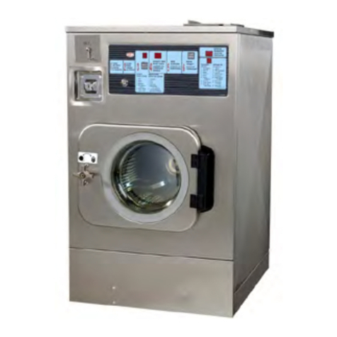
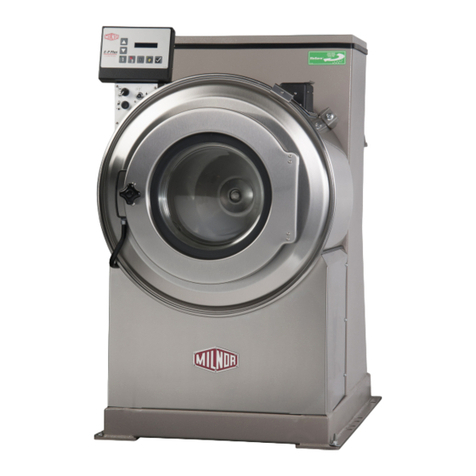
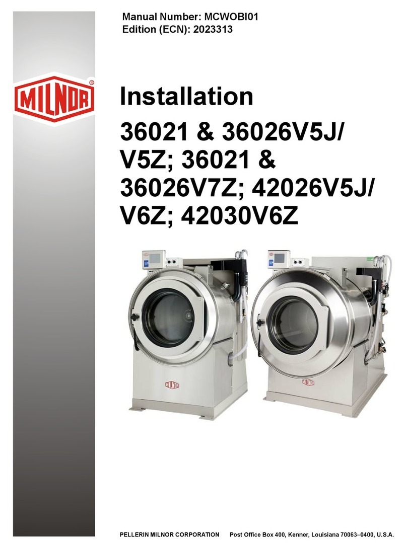
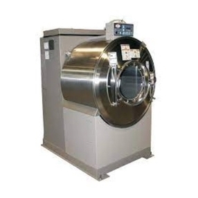
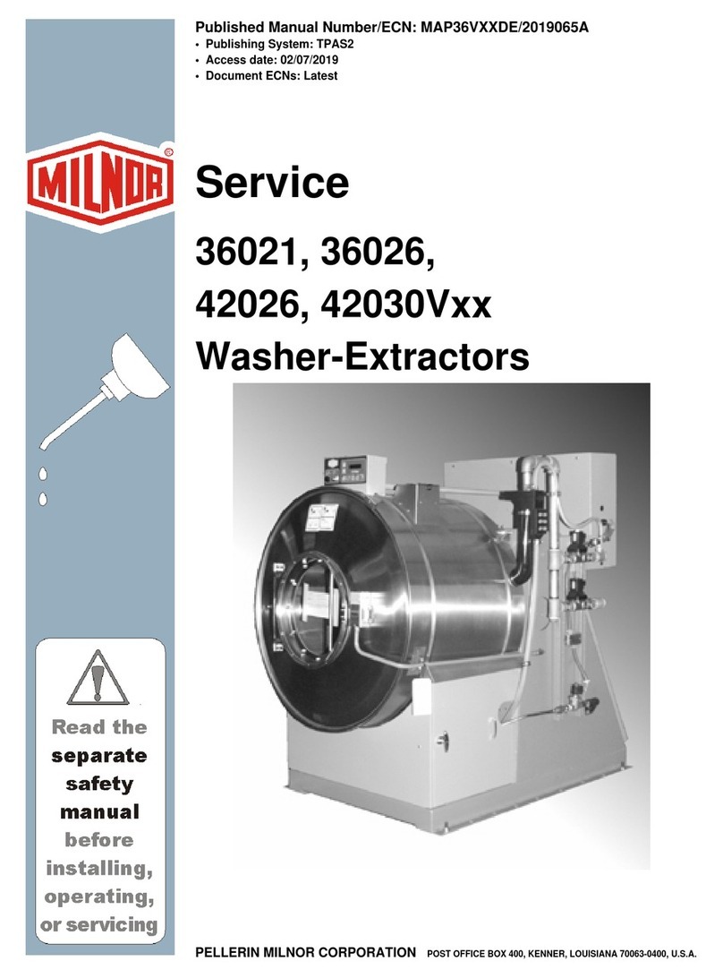
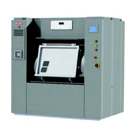
  9. Milnor Staphguard 42026 QHP User manual

Milnor Staphguard 42026 QHP User manual

Published Manual Number/ECN: ME6HWESSAE/89256N
• Publishing System: TPAS
• Access date: 3/4/2005
• Document ECN's: Exact
Schematic/Electrical Parts—
Staphguard Serial Controls
PELLERIN MILNOR CORPORATION POST OFFICE BOX 400, KENNER, LOUISIANA 70063-0400, U.S.A.
Please Read
About the Manual Identifying Information on the Cover
The front cover displays pertinent identifying information for this manual. Most important, are
the published manual number (part number) /ECN (date code). Generally, when a replacement
manual is furnished, it will have the same published manual number, but the latest available ECN.
This provides the user with the latest information applicable to his machine. Similarly all
documents comprising the manual will be the latest available as of the date the manual was
printed, even though older ECN dates for those documents may be listed in the table of
contents.
When communicating with the Milnor factory regarding this manual, please also provide the
other identifying information shown on the cover, including the publishing system, access date,
and whether the document ECN’s are the latest available or exact.
References to Yellow Troubleshooting Pages
This manual may contain references to “yellow pages.” Although the pages containing
troubleshooting procedures are no longer printed on yellow paper, troubleshooting instructions, if
any, will be contained in the easily located “Troubleshooting” chapter or section. See the table of
contents.
Trademarks of Pellerin Milnor Corporation
The following, some of which may be used in this manual, are trademarks of Pellerin Milnor
Corporation:
Ampsaver®Dye-Extractor®Gear Guardian®Milnet®Staph-Guard®
Autolint®Dyextractor®Hands-Off®Milnor®System 4®
Auto-Purge®E-P Express®Hydro-Cushion®Miltrac System 7®
Autovac E-P OneTouch®Mildata®Miltron Totaltrol®
CBW®E-P Plus®
Comments and Suggestions
Help us to improve this manual by sending your comments to:
Pellerin Milnor Corporation
Attn: Technical Publications
P. O. Box 400
Kenner, LA 70063-0400
Fax: (504) 469-1849
Table of Contents
for ME6HWESSAE/89256N
Staphguard Serial Controls
Page Description Document/ECN
1 Warranty BMP720097/92732A
3 How to Order Parts BMP720097R/72332A
4 Safety Instructions for Washer-Extractor Operation MSOP0205AE/9322CV
9 External Fuse & Wire Sizes for Washer Extractors:
42026QHP, QTL, QTN, 42031CP2, CP3, NP2,
NP3, SP2, SP3, WP2, WP3 BMP850045/94503V
10 External Fuse & Wire Sizes for Washer Extractors:
42044CP2, CP3, NP2, NP3, SP2, SP3, WP2,
WP3 BMP850047/96326V
11 External Fuse & Wire Sizes for Washer Extractors:
52038WP1, WTL, WTN, 72058J2N BMP850049/98271V
12 Drawing Identification - Forms and Format WWTBIFF/87082F
14 Drawing Identification - Forms and Format (continued) WWTBIFF-R/86466F
17 Machine Tags W6WESSTAG/89172D
18 Component List for W6WESSTAG W6WESSTAGR/89172N
19 Autospot W6WESSAS/86233D
20 Component List for W6WESSAS W6WESSAS-R/86233N
21 Autospot Clean Side W6WESSASC/86233D
22 Component List for W6WESSASC W6WESSASCR/86233N
23 Board to Board Wiring (Serial Controls) W6WESSBW/88467D
24 Component List for W6WESSBWA W6WESSBWAR/89251N
25 Flushing Supplies W6WESSCF/86233D
26 Component List for W6WESSCF W6WESSCF-R/86233N
27 Central Liquid Supply - Chem/Qty Select (1-6) W6WESSCL/86233D
28 Component List for W6WESSCL W6WESSCL-R/86233N
29 Clean & Soil Side Controls W6WESSCS/86233D
30 Component List for W6WESSCS W6WESSCS-R/86233N
31 Door Circuits W6WESSD/86233D
32 Component List for W6WESSD W6WESSD-R/86233N
33 Extract Commands Satisfied (Serial Controls) W6WESSEA/86416D
34 Component List for W6WESSEA W6WESSEA-R/86233N
35 Electrical Valves W6WESSEV/86233D
36 Component List for W6WESSEV W6WESSEV-R/86233N
37 Microprocessor Inputs W6WESSI/86243D
38 Component List for W6WESSI W6WESSI-R/86233N
39 Keypad and Display (Serial Controls) W6WESSKPD/86233D
40 Component List for W6WESSKPD W6WESSKPDR/86233N
41 Drive Motor Contactors (Serial Controls) W6WESSMC/86233D
42 Component List for W6WESSMCA W6WESSMCAR/89251N
43 M6 Divided Cylinder Motor Connections (Serial Controls) W6WESSMT/86233D
Table of Contents, cont.
Page Description Document/ECN
44 Component List for W6WESSMT W6WESSMT-R/86233N
45 Control Circuit Power W6WESSPS/86233D
46 Component List for W6WESSPS W6WESSPS-R/86233N
47 Start Circuit W6WESSS+/86233D
48 Component List for W6WESSS+ W6WESSS+-R/86233N
49 Speed, Door Circuits & Master Switch W6WESSSP/86233D
50 Component List for W6WESSSP W6WESSSP-R/86233N
51 3P Motor Diagram-Multivolt W80008/2001253A
53 How To Use Signal Routing Table MSTS0202BE/86082N
55 Signal Routing Table W6WESSRT/88062N
3(//(5,10,/125&25325$7,21
/,0,7('67$1'$5':$55$17<
We warrant to the original purchaser that MILNOR machines including electronic
hardware/software (hereafter referred to as “equipment”), will be free from defects in material
and workmanship for a period of one year from the date of shipment from our factory with no
operating hour limitation. This warranty is contingent upon the equipment being installed,
operated and serviced as specified in the operating manual supplied with the equipment, and
operated under normal conditions by competent operators.
Providing we receive written notification of a warranted defect within 30 days of its discovery,
we will – at our option – repair or replace the defective part or parts, FOB our factory. We
retain the right to require inspection of the parts claimed defective in our factory prior to
repairing or replacing same. We will not be responsible, or in any way liable, for unauthorized
repairs or service to our equipment, and this warranty shall be void if the equipment is repaired
or altered in any way without MILNOR’s written consent.
Parts which require routine replacement due to normal wear – such as gaskets, contact points,
brake and clutch linings and similar parts – are not covered by this warranty, nor are parts
damaged by exposure to weather or to chemicals.
We reserve the right to make changes in the design and/or construction of our equipment
(including purchased components) without obligation to change any equipment previously
supplied.
ANY SALE OR FURNISHING OF ANY EQUIPMENT BY MILNOR IS MADE ONLY UPON
THE EXPRESS UNDERSTANDING THAT MILNOR MAKES NO EXPRESSED OR IMPLIED
WARRANTIES OF MERCHANTABILITY OR FITNESS FOR ANY PARTICULAR USE OR
PURPOSE. MILNOR WILL NOT BE RESPONSIBLE FOR ANY COSTS OR DAMAGES
ACTUALLY INCURRED OR REQUIRED AS A RESULT OF: THE FAILURE OF ANY OTHER
PERSON OR ENTITY TO PERFORM ITS RESPONSIBILITIES, FIRE OR OTHER HAZARD,
ACCIDENT, IMPROPER STORAGE, MISUSE, NEGLECT, POWER OR ENVIRONMENTAL
CONTROL MALFUNCTIONS, DAMAGE FROM LIQUIDS, OR ANY OTHER CAUSE BEYOND
THE NORMAL RANGE OF USE. REGARDLESS OF HOW CAUSED, IN NO EVENT SHALL
MILNOR BE LIABLE FOR SPECIAL, INDIRECT, PUNITIVE, LIQUIDATED, OR
CONSEQUENTIAL COSTS OR DAMAGES, OR ANY COSTS OR DAMAGES WHATSOEVER
WHICH EXCEED THE PRICE PAID TO MILNOR FOR THE EQUIPMENT IT SELLS OR
FURNISHES.
WE NEITHER ASSUME, NOR AUTHORIZE ANY EMPLOYEE OR OTHER PERSON TO
ASSUME FOR US, ANY OTHER RESPONSIBILITY AND/OR LIABILITY IN CONNECTION
WITH THE SALE OR FURNISHING OF OUR EQUIPMENT TO ANY BUYER.
BMP720097
92732A
1
2
How to order repair parts
Repair parts may be ordered either from the authorized dealer who sold you this
machine, or directly from the MILNOR factory. In most cases, your dealer will
have these parts in stock.
When ordering parts, please be sure to give us the following information:
1. Model and serial number of the machine for which the parts are required
2. Part number
3. Name of the part
4. Quantity needed
5. Method of shipment desired
6. In correspondence regarding motors or electrical controls, please include all
nameplate data, including wiring diagram number and the make or
manufacturer of the motor or controls.
All parts will be shipped C.O.D. transportation charges collect only.
Please read this manual
It is strongly recommended that you read the installation and operating manual
before attempting to install or operate your machine. We suggest that this manual
be kept in your business office so that it will not become lost.
PELLERIN MILNOR CORPORATION
32%2;.(11(5/$86$
FAX: Administration 504/468-9307, Engineering 504/469-1849, Service 504/469-9777
BMP720097R
72332A
3
MSOP0205AE/9322CV (1 of 5)
ÈSAFETY INSTRUCTIONS
FOR WASHER-EXTRACTOR OPERATION
ÊGeneral Safety Requirements
(specific warnings, next page and throughout manual)
Incorrect installation, neglected preventive maintenance, abuse, and/or improper repairs or changes to
the machine can cause unsafe operation and personal injuries, such as multiple fractures, amputations, or
death. The owner or his selected representative (owner/user) is responsible for understanding and ensuring
the proper operation and maintenance of the machine. The owner/user must familiarize himself with the
contents of all machine instruction manuals. The owner/user should direct any questions about these instruc-
tions to a Milnor®dealer or the Milnor®Service department.
Most regulatory authorities (including OSHA in the USA) hold the owner/user ultimately responsible
for maintaining a safe working environment. Therefore, the owner/user must do the following:
•recognize all foreseeable safety hazards within his facility and take actions to protect his personnel,
equipment, and facility
•require that personnel are familiar with all functional and safety aspects of the machine
•ensure safety devices installed on the machine are in place and properly maintained
•ensure all machine parts and assemblies are properly maintained.
ËLaundry Facility—Provide a supporting floor that is strong and rigid enough to support--with a rea-
sonable safety factor and without undue or objectionable deflection--the weight of the fully loaded machine
and the forces transmitted by it during operation. (For washer-extractors, see “ABOUT THE FORCES
TRANSMITTED BY MILNOR®WASHER-EXTRACTORS.”) Provide sufficient clearance for machine
movement. Provide any safety guards, fences, restraints, devices, and verbal and/or posted restrictions nec-
essary to prevent personnel, machines, or other moving machinery from accessing the machine or its path.
Provide adequate ventilation to carry away heat and vapors. Ensure service connections to installed ma-
chines meet local and national safety standards, especially regarding the electrical disconnect (see the Na-
tional Electric Code). Prominently post safety information, including signs showing the source of electrical
disconnect.
ËPersonnel—Inform personnel about hazard avoidance and the importance of care and common sense.
Provide personnel with the safety and operating instructions that apply to them. Verify that personnel use
proper safety and operating procedures. Verify that that personnel understand and abide by point-of-hazard
tags on the machine and procedure-specific precautions in the instruction manuals.
ËSafety Devices—Ensure that no one eliminates or disables any safety device on the machine or in ths
facility. Do not allow machine to be used with any missing guard or cover. Service any failing or malfunc-
tioning device before operating the machine.
ËMaintenance—Ensure the machine is inspected and serviced in accordance with the norms of good
practice and with the preventive maintenance schedule. Replace belts, pulleys, brake shoes/disks, clutch
plates/tires, rollers, seals, alignment guides, etc. before they are severely worn. Immediately investigate any
READ BEFORE USING MACHINE!
4
ÊThe Danger From a Rotating Cylinder
A tremendous amount of potential energy is stored in the rotating cylinder of any washer-extractor
(even at slow speed). Washer-extractors are equipped with a door interlock designed to prevent the door
from being opened if the cylinder is turning and to prevent the machine from starting unless the door is
closed and locked.
Some smaller machines permit the door to be opened only during the first few minutes of the formula
and only while the machine is rotating in wash speed. If the door is opened, the drain valve opens immedi-
ately, the formula terminates, and (provided the machine still has electric power) on most, a brake is imme-
diately applied.
All larger washer-extractors are equipped with a spring-applied, air-released brake which remains ap-
plied as long as the door is open and stops the cylinder whenever any of the following occurs: 1) the extract
cycle ends, 2) the extract is manually terminated, or 3) the machine loses electric power.
Most machines permit the cylinder to be inched or jogged at slow speed, but only with two hands.
ENTANGLE HAZARD—The linen inside or hanging partially outside the
turning cylinder can suddenly wrap around your hand, arm, or body and
twist off/sever it.
☞DO NOT put any part of your body in the machine while it is moving.
☞DO NOT operate the machine with the door open.
☞DO NOT open the door while the cylinder is turning.
☞DO NOT touch the linen or load/unload machine while the cylinder is turning.
☞DO NOT open the door if there is water in the machine.You canbe scalded byhot water.
☞DO NOT tamper with or disable any safety device on the machine.
☞DO NOT operate the machine with a malfunctioning door interlock mechanism.
☞DO NOT operate the machine with malfunctioning two hand inching, if so equipped.
EXPLOSION HAZARD—A damaged cylinder can rip apart during extract,
throwing out metal fragments at high speed like an exploding grenade,
killing/injuring personnel and damaging property.
☞DO NOT operate machine with any evidence of cylinder damage.
ÊThe Danger From Processing With Flammable Materials
Washer-extractors are manufactured specifically for use with water,not with any type solvent nor with
any other material that might be flammable. They are not suitable for any type of solvent cleaning process.
EXPLOSION AND FIRE HAZARDS—Goods containing flammable materi-
als or fumes can explode or ignite spontaneously, killing/injuring person-
nel and damaging property.
☞NEVER process goods containing any significant quantity of flammable chemical.
C
B
SAFETY INSTRUCTIONS
FOR WASHER-EXTRACTOR OPERATION MSOP0205AE/9322CV (2 of 5)
5
ÊThe Danger From Operating With Guards or Covers Removed
Like other types of industrial equipment, Milnor®washer-extractors utilize high voltage electrical
power and, depending on model, pneumatic and hydraulic power to drive a wide variety of moving parts.
Even with external power completely removed, the machine may contain energy such as tensioned springs,
compressed air, and heavy parts that may fall if released. As previously stated, the washer cylinder acquires
tremendous potential energy during extract, which must be absorbed by the brake or permitted sufficient
time to dissipate. Every guard, side panel, and door on the machine exists to isolate energized or mov-
ing parts from laundry personnel and must be securely in place for safe operation.
ELECTROCUTION HAZARD—Electric boxes and other electrical compo-
nents contain high voltage that will kill or seriously injure you on contact.
Power switch(es) on the machine disable only control circuit power, not
three-phase power.
☞NEVER operate the machine with electric box doors open or any electrical con-
ductors exposed.
☞NEVER attempt any electrical repair or troubleshooting unless you are a qualified
electrician, authorized to work on the machine. Before proceeding, service per-
sonnel must consult all applicable safety and service information displayed on
the machine and provided in the manuals.
CRUSH AND ENTANGLE HAZARDS—Moving components such as belts,
hydraulics, tilting machine housings, etc., can entangle, crush and/or
sever parts of your body, killing or severely injuring you.
☞NEVER operate machine with any guards, covers, or side panels removed.
☞NEVER permit anyone to place any part of his body inside any part of the machine
housing when the machine is operational.
☞NEVER attempt any mechanical repair or troubleshooting unless you are a quali-
fied mechanic, authorized to work on the machine. Before proceeding, service
personnel must consult all applicable safety and service information displayed
on the machine and provided in the manuals.
☞ALWAYS make sure personnel are clear of machine before starting it.
SAFETY INSTRUCTIONS
FOR WASHER-EXTRACTOR OPERATION MSOP0205AE/9322CV (3 of 5)
6
ÊThe Danger From a Malfunctioning Clutch System
The low speed (wash speed) drive train on machines with multiple motor drives is disengaged during
extract. At the end of extract, the cylinder will slow down before the low speed drive train is permitted to
re-engage. Although extremely unlikely in a properly maintained machine, a malfunction could cause
the low speed drive to engage prematurely (a possibility in all types of industrial machines that utilize
clutches to switch between high speed and low speed operating cycles).
EXPLOSION HAZARD
for machines with multiple motor drives
—Pulleys
can be spun fast enough to explode into shrapnel-like fragments, injuring
personnel and/or damaging property, if the low speed drive engages dur-
ing or at the end of extract.
☞IMMEDIATELY shut down the machine if any of these conditions occur:
•The machine makes a sound like skidding automobile tires as it comes out of
extract,
•The wash or drain clutch does not disengage or it reengages during extract,
•V-belts jump off at the start of, during, or at the end of extract,
•A strange whining sound occurs at any time during extract.
☞DO NOT permit the machine to operate until the cause of the offending condition
is found and remedied.
SAFETY INSTRUCTIONS
FOR WASHER-EXTRACTOR OPERATION MSOP0205AE/9322CV (4 of 5)
7
ÊSpecial Safety Considerations for Tilting Machines
Restricted areas must be established and maintained around tilting machines to protect laundry
personnel from being struck or crushed when the machine tilts.
Tilt washer-extractors that pivot at both the front and rear of the machine have redundant safety limit
switches and electrical interlocks designed to prevent the machine from 1) tilting forward (rear up) unless
both front-down limit switches are depressed, and 2) tilting rearward (front up) unless both rear-down limit
switches are depressed. Because the safety limit switches and electrical interlocks cannot be bypassed at the
operator control panel, these ensure safe tilting during normal operation if the safety limit switches and all
related components and circuitry are in proper working order. Electrical interlocks and safety limit
switches are ignored when the machine is tilted manually with the hydraulic tilting valves. This proce-
dure must be restricted to competent, knowledgeable, authorized service personnel.
CRUSH HAZARD—Machine will crush body parts caught in mechanisms
during tilting. Personnel behind, above, or in front of machine may be
crushed if caught between machine and a nearby object during tilting.
☞NEVER tilt machine with any guards, covers, or side panels removed.
☞NEVER permit anyone to place any part of his bodyinside or undermachinewhen
the machine is operational.
☞NEVER permit anyone on top of the machine or within restricted areas around the
machine when the machine is operational. Laundry must restrict access to dan-
gerous areas.
☞ALWAYS ensure personnel are clear of machine before tilting.
☞NEVER operate a tilting machine unless all tilting components, including but not lim-
ited to safety limit switches, electrical interlocks, and operator controls, are function-
ing properly.
☞NEVER attempt to test or perform maintenance on any portion of the tilting
mechanisms unless you are a qualified mechanic authorized to work on the ma-
chine. Before proceeding, service personnel must consult all applicable safety
and service information displayed on the machine and provided in the manuals.
☞NEVER attempt to tilt the machine using the hydraulic tilting valves unless you
are a qualified mechanic authorized to work on the machine. Before using manual
hydraulic controls, service personnel must thoroughly understand the system
and all consequences of manual operation.
CRUSH HAZARD
for machines with both front and rear pivots
—A tilted
machine may lunge forward or rearward and even fall over, crushing per-
sonnel, if the tilt wheels at the non-tilted end are raised out of their cradles.
☞NEVER tilt machine using the hydraulic tilting valves unless you are a qualified me-
chanic authorized to work on the machine. These valves bypass all safeties.
C
SAFETY INSTRUCTIONS
FOR WASHER-EXTRACTOR OPERATION MSOP0205AE/9322CV (5 of 5)
8
BMP850045/94503V
È
EXTERNAL FUSE AND WIRE SIZES FOR WASHER EXTRACTORS:
42026 QHP,QTL,QTN;
42031 CP2, CP3, NP2, NP3, SP2, SP3, WP2, WP3
LARGEST MOTOR = 5HP
VOLT
CODE VOLTAGE
(VAC) RUNNING
AMPS
(NOTE 1)
PHASE FREQUENCY
(Hz) FUSE
(AMPS)
(NOTES 2, 4)
CIRCUIT
BREAKER
(AMPS)
(NOTE 4)
WIRE
PER NEC
(NOTES 3, 4)
AWG/mm2
46 200 17.5 3 50 FRN35 70 10 / 6.00
52 208 17 3 60 FRN35 70 10 / 6.00
62 220 16 3 50 FRN35 70 10 / 6.00
74 240 14.5 3 60 FRN30 60 10 / 6.00
81 346 10 3 50 FRS25 40 14 / 2.50
82 380 9 3 50 FRS20 35 14 / 2.50
83 380 9 3 60 FRS20 35 14 / 2.50
84 400 9 3 50 FRS17.5 35 14 / 2.50
85 415 8.5 3 50 FRS17.5 35 14 / 2.50
88 440 8 3 50 FRS17.5 35 14 / 2.50
96 480 7 3 60 FRS15 30 14 / 2.50
98 600 6 3 60 FRS15 25 14 / 2.50
NOTE 1: Running amps are for the highest demand portion of the cycle, after the motor is up to speed, and are approximate.
NOTE 2: Use Bussmann Fusetron FRN (up to 250V), FRS (250 to 600V) or similar lag type fuses.
CORRECT FUSE MUST BE USED—Never use fuses other than those specified. Extract mo-
tor may take up to two minutes to fully accelerate basket, during which time motor draws
nearly locked rotor current.
NOTE 3: Use wire size shown for runs up to 50 feet (15 meters). Use next larger size for runs 50 to 100 feet (15 to 30 meters). Use wire
two sizes larger for runs greater than 100 feet (30 meters).
CORRECT WIRE SIZE MUST BE USED —Never use wire of a smaller size than specified.
Smaller wire—even though its current-carrying capacity may be greater than the required
fuse—may cause voltage drops, thereby reducing starting torque. (A 5% voltage drop
causes motor to produce only 90% of its rated torque.) Note that the voltage drop is great-
est the instant the motor is energized, and thus when the highest torque is required.
NOTE 4: See section MSSM0118AE “FUSE AND WIRE SIZING” for more information.
9
BMP850047/96326V
È
EXTERNAL FUSE AND WIRE SIZES FOR WASHER EXTRACTORS:
42044 CP2, CP3, NP2, NP3, SP2, SP3, WP2, WP3
LARGEST MOTOR = 7.5HP
VOLT
CODE VOLTAGE
(VAC) RUNNING
AMPS
(NOTE 1)
PHASE FREQUENCY
(Hz) FUSE
(AMPS)
(NOTES 2, 4)
CIRCUIT
BREAKER
(AMPS)
(NOTE 4)
WIRE
PER NEC
(NOTES 3, 4)
AWG/mm2
46 200 25 3 50 FRN60 100 08 / 10.00
52 208 24 3 60 FRN50 100 08 / 10.00
62 220 23 3 50 FRN50 90 08 / 10.00
66 220 23 3 60 FRN50 90 08 / 10.00
74 240 21 3 60 FRN45 80 08 / 10.00
81 346 14.5 3 50 FRS30 60 10 / 6.00
82 380 13 3 50 FRS30 60 10 / 6.00
83 380 13 3 60 FRS30 60 10 / 6.00
84 400 12.5 3 50 FRS30 50 10 / 6.00
85 415 12 3 50 FRS25 50 10 / 6.00
88 440 11.5 3 50 FRS25 45 10 / 6.00
94 440 11.5 3 60 FRS25 45 10 / 6.00
96 480 10.5 3 60 FRS25 40 12 / 4.00
98 600 8.5 3 60 FRS20 35 12 / 4.00
NOTE 1: Running amps are for the highest demand portion of the cycle, after the motor is up to speed, and are approximate.
NOTE 2: Use Bussmann Fusetron FRN (up to 250V), FRS (250 to 600V) or similar lag type fuses.
CORRECT FUSE MUST BE USED—Never use fuses other than those specified. Extract mo-
tor may take up to two minutes to fully accelerate basket, during which time motor draws
nearly locked rotor current.
NOTE 3: Use wire size shown for runs up to 50 feet (15 meters). Use next larger size for runs 50 to 100 feet (15 to 30 meters). Use wire
two sizes larger for runs greater than 100 feet (30 meters).
CORRECT WIRE SIZE MUST BE USED—Never use wire of a smaller size than specified.
Smaller wire—even though its current-carrying capacity may be greater than the required
fuse—may cause voltage drops, thereby reducing starting torque. (A 5% voltage drop
causes motor to produce only 90% of its rated torque.) Note that the voltage drop is great-
est the instant the motor is energized, and thus when the highest torque is required.
NOTE 4: See section MSSM0118AE “FUSE AND WIRE SIZING” for more information.
10
BMP850049/98271V
È
EXTERNAL FUSE AND WIRE SIZES FOR WASHER EXTRACTORS:
52038 WP1, WTL, WTN;
72058 J2N
LARGEST MOTOR = 15HP
VOLT
CODE VOLTAGE
(VAC) RUNNING
AMPS
(NOTE 1)
PHASE FREQUENCY
(Hz) FUSE
(AMPS)
(NOTES 2, 4)
CIRCUIT
BREAKER
(AMPS)
(NOTE 4)
WIRE
PER NEC
(NOTES 3, 4)
AWG/mm2
46 200 48 3 50 FRN100 200 06 / 16.00
52 208 46.5 3 60 FRN100 200 06 / 16.00
62 220 44 3 50 FRN90 175 06 / 16.00
66 220 44 3 60 FRN90 175 06 / 16.00
74 240 40 3 60 FRN90 175 06 / 16.00
81 346 28 3 50 FRS60 110 08 / 10.00
82 380 25.5 3 50 FRS60 100 08 / 10.00
83 380 24 3 60 FRS60 100 08 / 10.00
84 400 24 3 50 FRS50 100 08 / 10.00
85 415 23 3 50 FRS50 90 10 / 6.00
88 440 22 3 50 FRS45 90 10 / 6.00
94 440 22 3 60 FRS45 90 10 / 6.00
96 480 20 3 60 FRS45 80 10 / 6.00
98 600 16 3 60 FRS35 70 10 / 6.00
NOTE 1: Running amps are for the highest demand portion of the cycle, after the motor is up to speed, and are approximate.
NOTE 2: Use Bussmann Fusetron FRN (up to 250V), FRS (250 to 600V) or similar lag type fuses.
CORRECT FUSE MUST BE USED—Never use fuses other than those specified. Extract mo-
tor may take up to two minutes to fully accelerate basket, during which time motor draws
nearly locked rotor current.
NOTE 3: Use wire size shown for runs up to 50 feet (15 meters). Use next larger size for runs 50 to 100 feet (15 to 30 meters). Use wire
two sizes larger for runs greater than 100 feet (30 meters).
CORRECT WIRE SIZE MUST BE USED—Never use wire of a smaller size than specified.
Smaller wire—even though its current-carrying capacity may be greater than the required
fuse—may cause voltage drops, thereby reducing starting torque. (A 5% voltage drop
causes motor to produce only 90% of its rated torque.) Note that the voltage drop is great-
est the instant the motor is energized, and thus when the highest torque is required.
NOTE 4: See section MSSM0118AE “FUSE AND WIRE SIZING” for more information.
11
12
13
14
15
16

This manual suits for next models

21

Other Milnor Washer manuals

Milnor 68036M5K Manual

Milnor

Milnor 68036M5K Manual

Milnor 30015T6X User manual

Milnor

Milnor 30015T6X User manual

Milnor 30015T6X User manual

Milnor

Milnor 30015T6X User manual

Milnor 42030V Series User manual

Milnor

Milnor 42030V Series User manual

Milnor Q4J Series User manual

Milnor

Milnor Q4J Series User manual

Milnor C Series User manual

Milnor

Milnor C Series User manual

Milnor 48032BTL Installation and operating manual

Milnor

Milnor 48032BTL Installation and operating manual

Milnor MWR12J5 User manual

Milnor

Milnor MWR12J5 User manual

Milnor MWF27J8 Manual

Milnor

Milnor MWF27J8 Manual

Milnor 42 Series Operating manual

Milnor

Milnor 42 Series Operating manual

Milnor MWR12X5 Quick start guide

Milnor

Milnor MWR12X5 Quick start guide

Milnor 30022X8R Operating manual

Milnor

Milnor 30022X8R Operating manual

Milnor 30022 User manual

Milnor

Milnor 30022 User manual

Milnor 48040F7J Operating manual

Milnor

Milnor 48040F7J Operating manual

Milnor 72044 WP3 User manual

Milnor

Milnor 72044 WP3 User manual

Milnor 48040M7K Manual

Milnor

Milnor 48040M7K Manual

Milnor 30015T6X Quick start guide

Milnor

Milnor 30015T6X Quick start guide

Milnor 42044WR2 Quick start guide

Milnor

Milnor 42044WR2 Quick start guide

Milnor 76028 G3 CBW Manual

Milnor

Milnor 76028 G3 CBW Manual

Milnor 42044SR2 User manual

Milnor

Milnor 42044SR2 User manual

Milnor Mark II Instruction Manual

Milnor

Milnor Mark II Instruction Manual

Milnor MWF63C7 Manual

Milnor

Milnor MWF63C7 Manual

Milnor 30022Fxx User manual

Milnor

Milnor 30022Fxx User manual

Milnor 36026X8J Operating manual

Milnor

Milnor 36026X8J Operating manual

Popular Washer manuals by other brands

Siemens WM14N21ODN User manual and installation instructions

Siemens

Siemens WM14N21ODN User manual and installation instructions

Asko W2084.W installation instructions

Asko

Asko W2084.W installation instructions

Beko EV 7100 Y user manual

Beko

Beko EV 7100 Y user manual

Beko WTV 8732 XS0 user manual

Beko

Beko WTV 8732 XS0 user manual

Bosch WFMC64 Repair manual

Bosch

Bosch WFMC64 Repair manual

Electrolux EWF 1408 ME1 user manual

Electrolux

Electrolux EWF 1408 ME1 user manual

Frigidaire Gallery GLWS1649AS2 operating instructions

Frigidaire

Frigidaire Gallery GLWS1649AS2 operating instructions

Beko WTC 6532 X0 user manual

Beko

Beko WTC 6532 X0 user manual

Viper SL10BOX owner's manual

Viper

Viper SL10BOX owner's manual

Bosch WAX32GH4GB User manual and installation instructions

Bosch

Bosch WAX32GH4GB User manual and installation instructions

Whirlpool 6AWTW5700XW0 Use and care guide

Whirlpool

Whirlpool 6AWTW5700XW0 Use and care guide

Beko WM 6155 W quick start guide

Beko

Beko WM 6155 W quick start guide

Beko WITC7652B user manual

Beko

Beko WITC7652B user manual

Beko WUE6512XBA user manual

Beko

Beko WUE6512XBA user manual

Haier HW80-B1439N user manual

Haier

Haier HW80-B1439N user manual

Signature SIG60 user manual

Signature

Signature SIG60 user manual

Panasonic NA-F75B3 Operating instructions & installation instructions

Panasonic

Panasonic NA-F75B3 Operating instructions & installation instructions

LG WT7005C Series owner's manual

LG

LG WT7005C Series owner's manual

manuals.online logo
manuals.online logoBrands
  • About & Mission
  • Contact us
  • Privacy Policy
  • Terms and Conditions

Copyright 2025 Manuals.Online. All Rights Reserved.