Milwaukee 48228560 User manual

Cat. No.
48228560
1524mm (60") STEEL MOBILE WORK STATION
OPERATOR'S MANUAL
WARNING To reduce the risk of injury, user must read and understand operator's manual.

2
IMPORTANT SAFETY INSTRUCTIONS
WARNING
Read all safety warnings and all
instructions. Failure to follow the
warnings and instructions may result in serious in-
jury. Save all warnings and instructions for future
reference.
•Use the bench and accessories in accordance
with these instructions and in the manner in-
tended, taking into account the working conditions.
Use of the bench for operations different from those
intended could result in a hazardous situation.
•Keep work area clean and well lit. Cluttered or
dark areas invite accidents.
•Fully assemble the bench according to the as-
sembly instructions. Do not leave off any pieces.
•Do not modify the bench in any way. Use only
specifically recommended accessories. Drilling
holes or modifying the bench will lower the load
capacity, which can cause the bench to collapse,
resulting in injury.
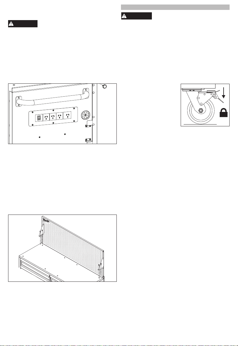
•Lock wheels when bench is not being moved.
Unlocked wheels can allow the bench to move
unexpectedly.
•Keep the bench on a level surface. Do not load,
unload, or park bench on an incline. The bench
may become unbalanced and tip, resulting in injury.
•Always balance the bench load to avoid tipping.
Unbalanced benches are more likely to tip when be-
ing moved or when using the bench work surfaces.
Evenly distribute the weight front to back and side
to side. To help prevent the bench from tipping,
load the product starting with the bottom drawers.
•Do not exceed the maximum product weight,
including contents. Do not exceed the maximum
weight for each drawer. Overloaded benches can
tip, collapse, or damage drawer slides.
•Do not open more than one drawer at a time.
Bench may tip, causing injury.
•Keep children and bystanders away while load-
ing, unloading, and moving bench. Distractions
can cause you to lose control.
•Only lift the bench according to the instructions
in this manual. Other methods may be dangerous,
resulting in injury.
•Only transport the bench when empty. Properly
secure when transporting.
•Do not mount the bench on a truck bed or any
other moving object.
•Lock all drawers before rolling the bench. The
drawers could come open and make the bench
unstable and tip.
•Only roll the bench short distances by using the
handle provided.
•Secure all items before rolling the bench. Loose
items could shift, causing the bench to become
unstable.
•Do not use drawers as steps. Do not stand
on the bench. Bench may tip, causing injury.
•Do not step on side shelf. Shelf may collapse or
break. Bench may tip, causing injury.
•Do not use bench in explosive atmospheres,
such as in the presence of ammable liquids, gases
or dust. This equipment has internal arcing or spark-
ing parts. Bench should not be located in a recessed
area or below oor level.
•Bench plugs must match the outlet. Never mod-
ify the plug in any way. Do not use any adapter
plugs with earth (grounded) chest/cabinet power
strips. Unmodied plugs and matching outlets will
reduce risk of electric shock.
•Avoid body contact with earthed or grounded
surfaces such as pipes, radiators, ranges and
refrigerators. There is an increased risk of electric
shock if your body is earthed or grounded.
•Maintain bench. Check for misalignment or binding
wheels, breakage or bending of drawer slides or
other parts and any other condition that may affect
the bench's operation. Do not use damaged bench.
•Maintain labels and nameplates. These carry
important information. If unreadable or missing,
contact a MILWAUKEE service facility for a free
replacement.
•Have your bench serviced by a qualied repair
person using only identical replacement parts.
This will ensure that the safety of the bench is
maintained.
SYMBOLOGY
Warning
Read Operator's Manual
Electrical Shock Hazard
Do not open more than one drawer at a
time. Bench may tip, causing injury.
Lock wheels when bench is not
being moved. Unlocked wheels can
allow the bench to move
unexpectedly.
Do not use drawers as steps. Bench
may tip, causing injury.
FPO
Lock all drawers before moving the bench.
Do not step on side shelf. Shelf may
collapse or break. Bench may tip, causing
injury.
SPECIFICATIONS
Cat. No....................................................48228560
Two-Slide Drawer Capacity .........45.4 kg (100 lbs.)
Four-Slide Drawer Capacity ........90.7 kg (200 lbs.)
Peg Board Capacity.....................90.7 kg (200 lbs.)
Total Capacity ..........................997.9 kg (2200 lbs.)

3
FUNCTIONAL DESCRIPTION
18
20
1
15
14
13
1110
5
1. Peg board
2. Tool hanger
3. Wood work
surface
4. Cabinet shelf
5. Cabinet shelf clip
6. Key
7. Swivel caster
with brake
8. Drawer divider
9. Lock
10. Rigid caster
2
3
17
16
4
6
11. Tool organizer
12. Drawer slide
13. Bumper
14. Storage shelf
15. Charger mounts
16. Cord storage
bracket
17. Side handle
18. Power strip
19. Locking thumb
screw
20. Peg board bracket
789
12
19
ASSEMBLY
CAUTION
Be sure to follow the assembly in-
structions for the appropriate
bench. Do not use power tools to assemble
bench. Tighten bolts with hand wrenches.
Tools Required
Phillips
screwdriver
Safety
goggles
10 mm
Wrench
13 mm
Wrench
Hardware Included
NOTE: Items not shown to actual size.
Hard-
ware Item Description Quantity
AA Screw M4 x 10L 8
BB Screw 1/4" x
3/4"L 4
CC Bolt M6 x 15L 12
DD Washer 24
EE Bolt M8 x 15L 24
FF Screw M6 x 15L 8
Item Description Quantity
Side handle 1
Tool hanger 1
Swivel caster with
brake 4
Rigid caster 2
Bumper 4
Cord Storage
Bracket 2
Peg Board Bracket 2
Locking Thumb
Screw 2

4
4. Mount the two rigid casters in the middle of the
bench using four bolts (EE) and washers (DD)
per caster.
5. Tighten all bolts up to nger tight and then using a
wrench apply no less than 1/2 (180°) turn.
6. Return the bench to its upright position.
Installing the Drawer Liners
Place the drawer liners in appropriately sized drawers
to protect the surface.
Installing the Bumpers
Attach the four bumpers to the bench using two
screws (FF) per bumper. Turn screws to nger tight
then secure with 1/4 (90°) turn with a phillips head
screwdriver.
Installing the Cord Storage Brackets
Attach the brackets to the bottom right of the bench
power strip with two screws (AA) per bracket. Turn
to nger tight and then secure with a 1/4 (90°) turn
with a phillips head screwdriver. Orient the brackets
with one pointed up and one pointed down so that
the power outlet cord can be wrapped around the
brackets for storage.
Attaching the Tool Hanger
Attach the tool hanger to the left end of the bench
using two bolts (CC). Turn to nger tight and then
secure with a 1/4 (90°) turn with a phillips head
screwdriver.
Attaching the Storage Shelf
Attach the storage shelf to the bench using two bolts
(CC) on either end of the bench. Turn to nger tight
and then secure with a 1/4 (90°) turn with a phillips
head screwdriver.
Cabinet Shelf 1
Cabinet Shelf Clip 4
NOTE: Begin product assembly close to the nal
intended location of your bench. This product is
heavy and may be difcult to move after assembly.
Attaching the Side Handle
Attach the side handle to the bench using four bolts
(CC). The side handle can be attached to either
side of the bench. Tighten all 4 bolts up to nger
tight, then using a wrench apply 3/4 (270°) turn to
secure properly.
NOTE: The holes in the bench are tapped and do
not require nuts.
Installing the Casters
CAUTION
Two people may be required to
complete installation.
CAUTION
Do not overtighten the screws.
1. Ensure all bench drawers are securely locked into
place using the key lock on the bench.
2. Lay the bench on its back. Use the packaging
material to protect the nish.
3. Mount the four swivel casters with brake to the
bench using four bolts (EE) and washers (DD)
per caster. The swivel casters with brake should
be installed on both ends of the bench.

5
Positioning the Peg Board
CAUTION
Do not hang any objects on the peg
board without securing the board
in place.
The peg board is shipped and secured in its stored
location. To raise the peg board to a usable height,
remove the locking thumb screws at the top of the peg
board slides. The peg board can be raised to either
mid or full height position by pulling straight up. When
in mid or full height position, two pairs of ball detents
will temporarily hold the peg board in place. The lock-
ing thumb screw holes and the tapped holes located
in the frame of the peg board will align. Reinstall the
locking thumb screws to secure the peg board.
CAUTION! The locking thumb screws must be
installed before hanging objects on the peg board.
For increased stability of the peg board, peg board
brackets and hardware are provided. To install brack-
ets, locate the tapped holes on both ends of the peg
board, just above the bench work surface. Mount the
peg board brackets on both ends of the peg board
frame using two bolts (CC) per bracket. With the foot
of the bracket resting in position on the wood work
surface, mark the position of each bracket hole and
drill 1/8” holes approximately ¾” deep. Use screws
(BB) to secure the peg board brackets to the wood
work surface. Turn to nger tight and then secure
with a 1/4 (90°) turn using a phillips head screwdriver.
Reversing the Wood Work Surface
The wood work surface comes pre-installed with
the bench. After wear and tear, the surface may
be reversed to use the clean bottom surface. To
reverse, remove the eight screws from the top of
the wood work surface, ip surface, and reinstall
the eight screws.
OPERATION
WARNING
To avoid injury or property damage,
do not exceed maximum shelf and
drawer capacity. Use care when moving bench
on incline or rough surface. Bench may tip if
weight is not evenly distributed front to back and
side to side. Place more than half the total load
weight on the bottom drawers when possible.
Locking and Unlocking the Bench
NOTE: The drawers must be fully closed before
locking/unlocking the unit.
Insert the key. Turn it fully left to lock, or fully right
to unlock. Always remove the key after locking and
unlocking.
Using the Caster Brakes
To lock the swivel casters,
step down on the levers
marked ON. Be sure to lock
all casters to prevent bench
from rolling or swiveling. To
unlock casters, push down
on the levers marked OFF.
Moving the Bench on an Incline or
Rough Surface
Take care that the bench does not tip or become
unbalanced when moving it on an incline or rough
surface. Do not exceed an incline of 10 degrees.
Lock the bench and secure all items before moving.
Rolling the Bench
The bench is only intended for rolling short distances.
Only roll the bench using the handle. Do not push or
pull bench by the frame or product may tip. Do not
modify the bench in any way. Drilling holes or modi-
fying the bench will lower the load capacity, which
can cause the bench to collapse, resulting in injury.
Lock the bench and secure all items before rolling.
Lifting the Bench
The bench is not intended to be lifted. However, if you
need to lift, empty the bench and then place straps
or forks inside and next to casters. Do not lift loaded
benches. Be sure all bystanders are moved away
before lifting bench.
Mounting Chargers
The rolling cabinet comes equipped with four pre-
installed charger mounting bosses, located below
the power strip. The charger mounts are suitable for
holding MILWAUKEE M18™ & M12™ Multi Voltage
chargers as well as M18™ chargers. To mount a
charger, install a screw (AA) into each boss, then
slide the charger's key-hole slots over the screws.
Slide the charger toward the oor to lock it onto the
screws.

6
Removing the Drawers
1. Fully extend and empty the drawer.
2. Depending on the side, either lift or lower the
release lever on both sides so the slides can ride
over the stops. Pull out to remove.
Release Lever
Installing the Drawers
1. Pull the slides and slide carrier out until fully ex-
tended.
2. Hold the slide on the cabinet while aligning it with
the slide on the drawer.
3. Slightly insert one side and repeat for the other
side.
4. Slowly push the drawer until it is fully closed to
engage the slide.
5. Open and close the drawer to verify proper op-
eration.
MAINTENANCE
WARNING
To reduce the risk of injury, contact
MILWAUKEE Corporate After Sales
Service Technical Support for ALL repairs and
replacement parts.
Maintaining the Bench
Keep your bench in good repair by adopting a regular
maintenance program. Before use, examine the gen-
eral condition of your bench. Check for loose screws,
misalignment, binding of wheels, broken parts and
any other condition that may affect its safe operation.
Do not use a damaged bench.
Maintaining the Casters
Grease the casters annually using high quality bear-
ing grease.
Grease
Points
Maintaining the Drawers
1. Periodically clean the drawer with a mild detergent
and water.
2. Remove grease and oil in drawer with a standard,
nonammable cleaning uid.
3. The use of drawer liners is recommended to
protect the nish inside the drawers and make
the drawers easier to clean. Drawer liners can be
cleaned with soap and water.
4. Lubricate the slides semi-annually with general
purpose grease or equivalent.
Grease
Points
Cleaning
This steel product has been coated with industrial
powder coating for a durable nish. To help protect
the powder coated nish, do not allow harsh chemi-
cals (oil, grease or other chemical) to remain on the
powder coating surface. Use a glass cleaner to clean
and maintain all surfaces of powder coating.
Keep the bench handles and wheels clean, dry and
free of oil or grease. Use only mild soap and a damp
cloth to clean your bench since certain cleaning
agents and solvents are harmful to plastics. Some of
these include: gasoline, turpentine, lacquer thinner,
chlorinated cleaning solvents, ammonia and house-
hold detergents containing ammonia. Never use
ammable or combustible solvents around bench.
ACCESSORIES
WARNING
Modifying the bench to accept
other accessories may be hazard-
ous, resulting in injury or property damage. Use
only specically recommended accessories ac-
cording to the manufacturer's instructions.

7

48228560 Printed in Vietnam
WARRANTY - AUSTRALIA and NEW ZEALAND
Please refer to Australia and New Zealand warranty supplied with tool. This warranty applies only to
product sold in Australia and New Zealand.
AUSTRALIA and NEW ZEALAND MILWAUKEE® Service
MILWAUKEE® prides itself in producing a premium quality product that is Nothing but Heavy Duty®.
Your satisfaction with our products is very important to us! If you encounter any problems with the
operation of this tool, please contact your authorised MILWAUKEE® dealer.
For a list of MILWAUKEE® dealers, guarantee or service agents please contact MILWAUKEE®
Customer Service or visit our website.
(Australia Toll Free Telephone Number 1300 361 505)
(New Zealand Toll Free Telephone Number (0800 279 624) or visit www.milwaukeetools.com.au /
www.milwaukeetools.co.nz.
Milwaukee Electric Tool Corporation
13135 West Lisbon Road, Brookeld, Wisconsin U.S.A. 53005
Milwaukee Electric Tool Corporation (Australian)
Techtronic Industries (Australia) Pty. Ltd.
Rowville, Victoria, Australia, 3178
Milwaukee Electric Tool Corporation (New Zealand)
Techtronic Industries (New Zealand) Pty. Ltd.
Mangere, Auckland, New Zealand, 2022
Table of contents