INSTALLATION INSTRUCTIONS
FOR VSP D2
INTRODUCTION
Thank you for selecting & purchasing
MINILEC make phase failure relay VSP D2.The
following installation instructions would guide
you in installing your VSP D2 and making best
use of it.
VSP D2 is a phase failure relay operating on
negative sequence voltage sensing principle. It
offers protection against
* Unbalanced voltage condition.
* Phase failure condition.
* Phase sequence reversal condition.
Your VSP D2 is an auxiliary relay and it should be
used along with the motor starter only. The
effective working of VSP D2 will depend on
efficient working of the electromagnetic motor
starter. Before installing your VSP D2 check
whether the motor starter is operating perfectly by
starting the Motor with the “START” push button
and switching it off by “OFF” push button. If the
motor does not “START” or “STOP” on respective
operations, the starter needs to be serviced. Do
not install your VSP D2 with faulty motor starter.
TRIP SETTING, TRIP DELAY AND
. RESETTING
You can set your VSP D2 relay to trip the starter for
any unbalance voltage between 30V to 70V K6V
between any two phases.
The trip time delay is between 2 to 5 secs. The
VSP D2 relay can be set in Auto reset mode or
manual reset and remote reset mode by removing
or putting a short link between terminals 11&12.
VSP D2 will reset when the unbalance voltage is
reduced to less than 20V between all three
phases.
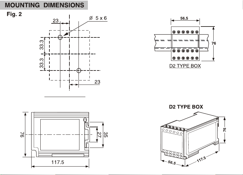
MOUNTING
Your VSP D2 can be Rail Mounted or Panel
Mounted.(See fig. 4A & 4B for mounting it on RAIL
and releasing it from RAIL respectively). It is
suitable for 35mm RAIL ( for panel mounting and
drilling details see fig.2 ).
CAUTION
1) Ensure that your VSP D2 is -
* Not installed near any heat sources like
burner, sunlight, electric arc etc.
*Not subjected to abnormal vibrations.
*Installed as near to the starter as possible.
2) 3 0
/
sensing (L1,L2,L3) is normaly taken from
outgoing terminals of motor starter. But in
.following conditions, sensing should be
. taken from incoming of motor starter, when
. VSP D2 is used in Automatic reset mode.
* Fully automatic starter.
* Multi speed motor starter.
* Reversible starters.
* When any other auto resetting type control
.switch is used in series with no volt coil of the
.starter.
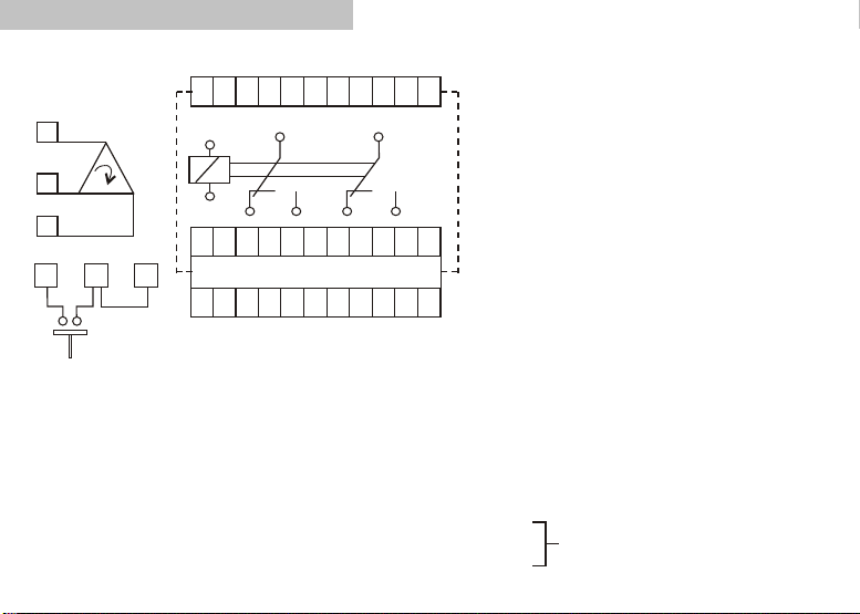
ELECTRICAL CONNECTIONS OF VSP D2:
See Fig.1 for Electrical connection
details of VSP D2.
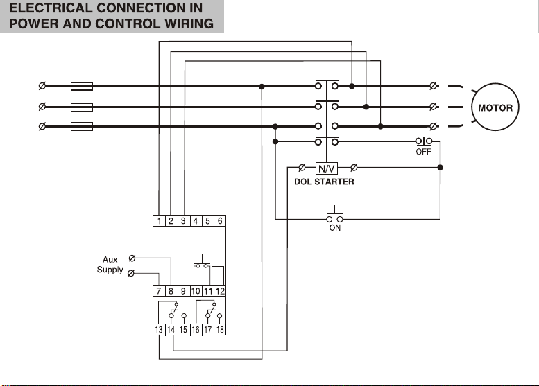
See Fig.3 for installation of VSP D2 in the
power and control wiring.
Auxiliary supply voltage should be as marked
on the front cover plate of VSP D2.
Connect the auxiliary supply wires at 7 & 8.
Connect R,Y,B phases at 1,2 and 3 respectively.
The R,Y, B sensing should be taken from outgoing
points of motor starter in case of Direct Online
Starter. In case of star delta starters, it should be
taken from outgoing terminals of main contactor.
The output relay contacts 13 and 14 is to be
connected in series with no-volt coil of the
contactor. The potential free output relay contact
16 & 18 can be connected to annunciator or used for
trip indication.
TECHNICAL SPECIFICATIONS
OF VSP D2
1. SYSTEM SUPPLY VOLTAGE :
220 / 230 / 240 / 380 / 415 VAC K20 %
2. AUX. SUPPLY :
110 / 220 / 230 / 240 / 380 / 415 VAC K 20%
3. FREQUENCY : 50 / (60) Hz, K3%
4. POWER CONSUMPTION : 3 VA ( max.)
5. OUTPUT RELAY CONTACT : 2 Changeover
6. OUTPUT CONTACT RATING [ RESISTIVE ] :
5Amp., 240 VAC
7. LIFE EXPECTANCY :
6
0.5 x 10 operations at 100% rating
8. UNBALANCE TRIP SETTING :
30 to 70V K6V
9. SET ACCURACY : K10% of set value
10. TRIP TIME DELAY :
3.5 Sec. K 1.5 Sec.
11. TEST PUSH BUTTON DELAY :
3.5 Sec. K1.5 Sec
12. RESETTING : Auto, Manual, Remote Reset
13. RESET GAP : 10 - 18V
14. INDICATION :
L1 : Green - Power ON
L2 : Red - Trip
15. ENCLOSURE : ABS.
16. DIMENSIONS [mm] :
Overall :76 x 56.5 x 117.5 [ LXWXD ]
Mounting : 67 x 46 [ LXW ]
17. MOUNTING :
35 mm Rail Mounting & Panel Mounting
18. WEIGHT [gms] : 400 (approx.)
19. OPERATING CONDITIONS :
00
TEMPERETURE : -5 C to + 60 C
HUMIDITY : Upto 95% R.H.
TESTING :
.
If you need to test the functioning of VSP D2 without connecting it in the control circuit of the motor
starter, follow the following procedure. Connect required auxiliary supply to VSP D2. Check the output
relay contacts at (13) & (14). Indication L1 should be ON. Press TEST push button on the front of the
VSP D2. Reset your VSP D2 by either pressing RESET push button on the front plate of VSP D2 or by
shorting terminals (10) & (11) of VSP D2 . If these operations are perfect, connect your VSP D2 in the
motor circuit. Consult Minilec if you find any irregularities in the above mentioned operation.
TESTING PROCEDURE
Wait till
supply
voltage
normalizes
Is it
within the
specified
tolerance
limits?
Check Aux.
supply voltage
at 7 & 8 of
VSP D2
Is
L1
ON ?
See Indication
Start
R,Y,B phase sequence
connected to VSP D2
is correct.
Start motor
Does
starter
hold
Now remove any one
fuse link in power
circuit for all the 3
phases one at a time
Does
VSP D2 trip
within 2-5 secs
& L2 get ON ?
Reset the relay and restart
VSP D2 operation is perfect.
Install it for permanent use
R,Y,B phase
sequence is incorrect
interchange wires
of 1 & 3 of VSP D2 .
Tighten all terminals
in power & control
wiring & at 1,2&3
of VSP D2
Check phase to phase voltage
across 1,2& 3 of VSP D2 after
removing fuse link.
NO
CONSULT
MINILEC
YES
Is
phase to phase
unbalance voltage
less than unbalanced
setting of
VSP D2
Set the unbalance voltage
setting at 30 V (minimum) &
reset the relay as per above steps.
YES
NO
NO
NO
NO
YES
END
VSP D2 will not trip Load
the motor & retest as per
above procedure.
YES
YES
D - dt.25/8/04