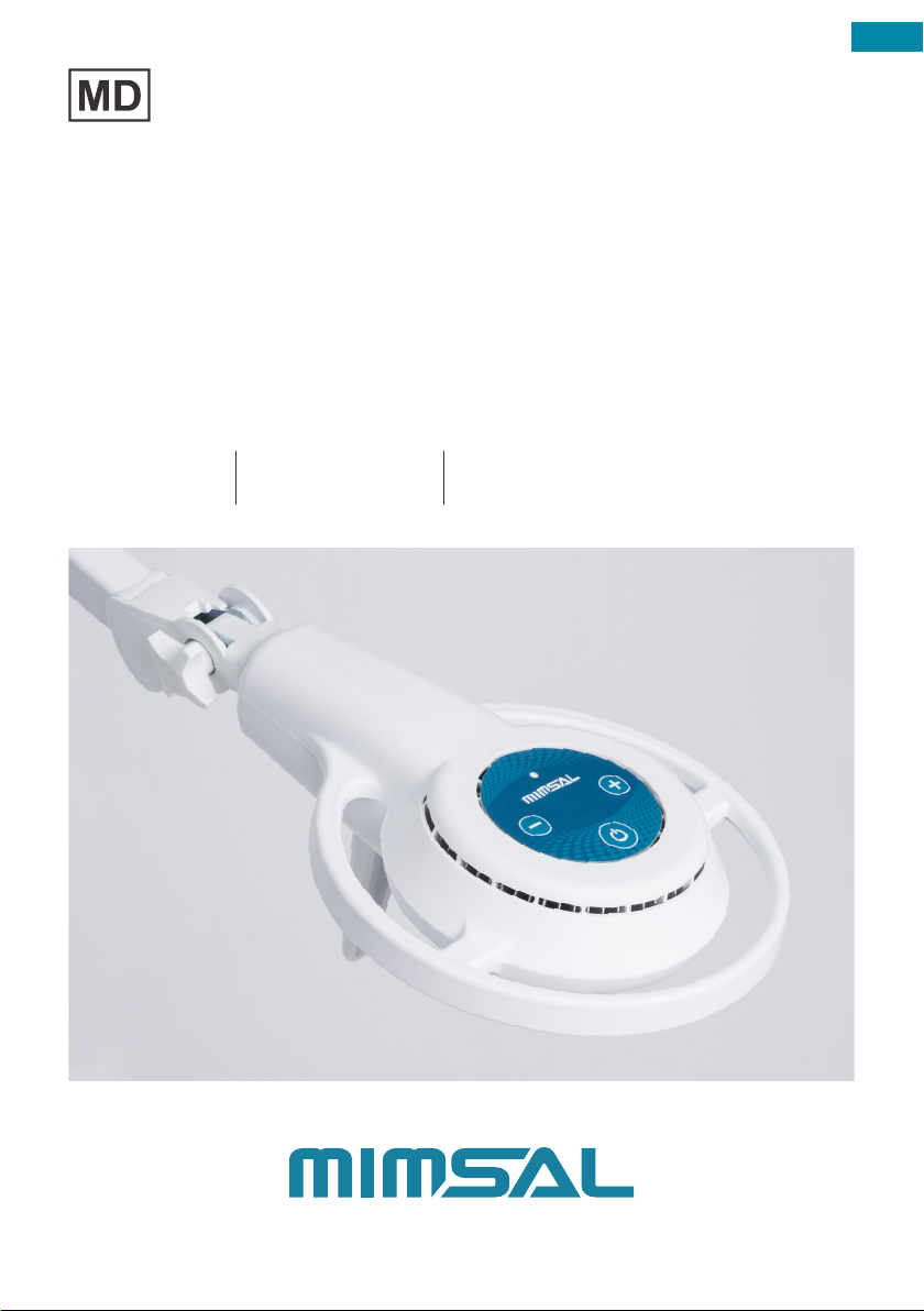
MIMSAL MS User manual

ENG
USER MANUAL
MS
EXAMINATION LAMP
MS LED
MS LED PLUS
MS FLEX
MS FLEX PLUS
MS CEILING
MS CEILING PLUS
F3P30
Rev. 01
20.06.2022

ENG
Dear user, we encourage you to read this manual carefully before using the product.
The manufacturer states that this product complies with Annex I (General safety and performance
requirements) of (EU) REGULATION 2017/745 on medical devices, amended and integrated.
This manual’s content may be modified in part or in whole by MISMAL without prior notice in
order to make changes and improvements.
MIMSAL has a Customer Support service available.
Your team:
MIMSAL TRADE S.L.
C/ Mollet, 17
Polígono Industrial Palou Nord
08401 – Granollers (Barcelona) SPAIN
Tel. +34 930 139 860
mimsal@mimsal com
www.mimsal.com

ENG
3
TABLE OF CONTENTS
1.Safety instructions 5
2. Brief description 6
3. Installation and supports 7
3.1 Trolley Stand 8
3.2 AH Table Clamp 9
3.3 Wall B Support 10
3.4 Rail Plus Bracket 11
3.5 Extension arm 12
3.6 Ceiling Support 13
4. Operation of the lighting unit 15
4.1 Check before each use 15
4.2 Operation of the lighting unit head 15
4.3 Arm measurement detail by MS model 16
5. Safety functions 18
5.1 Voltage drop 18
5.2 Power cuts 18
5.3 Electrical malfunction 18
6. Cleaning/Disinfection 18
6.1 General safety instructions 18
6.2 Cleaning 18
6.3 Disinfection 19
7. Maintenance 19
7.1 Lighting unit support arms 19
7.2 Lighting unit head 20
7.3 Repairs 20
7.4 Adjustments 20
7.5 Troubleshooting 20
8. Recycling 20
9. Technical data 21
10. Electromagnetic Emissions 22
11. Warranty 24
12. Industrial and Intellectual Property 25
13. Confidentiality 25
14. Declaration of Conformity 26
15. Certificate ISO 9001 27
16. Certificate ISO 13485 28

ENG
4
SYMBOLS
INSTRUCTIONS
DECLARATION OF CONFORMITY
MEDICAL DEVICE
ITEM CODE
BATCH NUMBER
MANUFACTURING DATE
NAME AND ADDRESS OF THE MANUFACTURER
ELECTRONIC WASTE RECYCLING
ELECTRICAL INSULATION CLASS
Class II
MINIMUM DISTANCE TO THE ILLUMINATED OBJECT
AMBIENT TEMPERATURE
Shows the permitted ambient temperature of between -25°C and 70°C for transportation and
storage.
HUMIDITY
Shows the permitted humidity values of between 10% and 75% for transportation and storage.
WARNING
Not doing so could result in serious or even fatal injuries.
CAUTION
Not doing so could result in minor to moderate injuries or damage.
NOTE | INFORMATION
Provides application tips and useful information.
FALLING OF THE LIGHTING UNIT
Warns about the sudden collapse of the support arm system if the maximum useful load is
exceeded.
TIPPING HAZARD
The brackets are only designed to support the weight of the head. If additional weight is added, the
unit may tip over, which could cause damage of varying degrees.
SAFETY RULES

ENG
5
REFERENCE AND MODEL
REF MODEL UDI-DI
M187001C MS CEILING PLUS 8436562860493
M183500C MS CEILING 8436562860486
M187001 MS LED PLUS 8436562860394
M183500 MS LED 8436562860387
M187001FL MS FLEX PLUS 8436562860431
M183500FL MS FLEX 8436562860424
1. SAFETY INSTRUCTIONS
Check the operating instructions when handling the device.
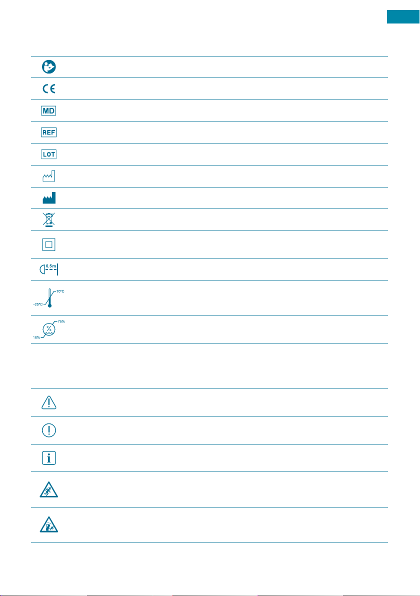
This lighting unit is a Class I medical device according to (EU) Regulation 2017/745 on
medical devices.
ENVIRONMENT
1. This device is not designed to be operated in potentially explosive areas!
2. Do not use it in oxygen-enriched areas!
3. Do not use it near flammable anesthetic gases!
4. Do not place it close to strong magnetic fields! e.g. Magnetic resonance systems.
5. Do not cover the top of the lamp head! Risk of overheating!
ELECTRONIC SAFETY
1. Only use the built-in power source unit!
2. The lighting unit does not include a fail-safe power source or an emergency battery!
3. In the event of a power cut, the lighting unit will shut off completely!
4. Short black-outs are possible in the event of external EMC interference!
5. To switch off the lamp completely, the power plug must be removed from the outlet or the
live outlet must be disabled using a separate switch.
MAINTENANCE AND RESPONSABILITY
1. Installation and electrical maintenance work must only be carried out by qualified personnel!
2. The manufacturer is not responsible for any damage caused by improper use!
3. The final user is responsible for the product’s installation and MIMSAL accepts no responsibility.
4. The manufacturer is responsible for the safety of the lamp only if repairs and modifications are
carried out by the manufacturer itself or by a company that ensures compliance with safety
rules, using original replacement parts!
Prior to each use, make sure that the lamp is in perfect technical condition.

ENG
6
2. BRIEF DESCRIPTION
INTENDED USERS
These operating instructions are intended for the health professionals who use, clean, and
disinfect MISMAL lighting units.
INTENDED USE
This lighting unit is intended for carrying out very meticulous work that requires a high level of
precision. It is suitable for use in hospitals, medical research, laboratories, clinics, etc.
INDICATION
The light is only intended to provide optimal visibility of the surface being examined and has no
diagnostic or therapeutic effect. The light is external to the body and the device never enters
into contact with patients.
CONTRAINDICATION
The products must not be used close to strong magnetic fields.
The device must not be used in oxygen-enriched environments or in close to flammable
anesthetic gases.
RESIDUAL RISKS – RISK IN THE EVENT OF DAMAGE TO THE LIGHTING UNIT
Protect the lighting unit from knocks. Collision with other objects could result in the failure of
the device and/or damage to the cover and the support arm system, causing parts to fall off.
The lighting unit does not include a fail-safe power source. A power cut will cause the device
to switch off.
Do not aim the light source directly at the eyes of the patient and/or operator.
Always properly protect the patient’s eyes.
Failing to comply with these precautions could cause blinding and damage to the retina.
Never place and/or hang any object on the lighting unit. If this precaution is not taken, the unit’s
position will be unstable and these objects could fall onto the work area.
Never hang the body weight of a person from the lighting unit. Failing to comply with this
precaution could damage the structure of the device.
INCIDENTS AND REPORTS
The user and/or the patient must notify MISMAL and the competent authority in the country if
any serious incident occurs whilst using the device.
In accordance with the Medical Devices Regulation (MDR), the competent authority must be
notified immediately.

ENG
7
SUPPORTS FOR: MS CEILING PLUS | MS CEILING
MODEL SUPPORT
TROLLEY STAND Rolling base with 5 wheels
AH TABLE CLAMP Table clamp
WALL B SUPPORT Reinforced wall B bracket
RAIL PLUS BRACKET Bracket for mounting on an ICU rail
EXTENSION ARM Extension arm + Reinforced wall B bracket
* All of these MS models include the AH TABLE CLAMP mounting accessory by default.
MODEL SUPPORT
CEILING SUPPORT Ceiling bracket
* The MS CEILING PLUS and MS CEILING already include a CEILING SUPPORT.
* Not compatible with MS LED, MS LED PLUS, MS FLEX and MS FLEX PLUS.
3. INSTALLATION AND SUPPORTS
Before starting to install the device, check that the content is in good condition and that it has
not been damaged or degraded during transportation.
Claims will only be accepted if the vendor or the carrier is notified immediately. All claims must
be made in writing.
The goods always travel under the buyer’s responsibility and at the buyer’s risk.
Keep the original packaging in the event the product needs to be returned.
TYPES OF SUPPORT
The lighting unit may come with several different types of brackets, allowing the most suitable
one to be selected for its use.
All accessories must be assembled by an authorized installer.
Do not make any modifications to the product, other than those mentioned in this user manual.
SUPPORTS FOR: MS LED PLUS | MS LED | MS FLEX PLUS | MS FLEX

ENG
8
1u. 8,8 Kg
Allen n. 2
3.1 TROLLEY STAND
REF MODEL DESCRIPTION
09651 TROLLEY STAND 8,8 Kg 8.8 Kg rolling base
1. Installation and assembly
- Insert piece (2) totally into the base (3) and press down.
- Insert the legs with the wheels (4) through the base slot (3) until it completely fits, and if
necessary helping with a nylon hammer.
- Fit piece 5 into the interior leg slots (4) by pressing down.
- Put the screw (7) through the washer (6) and insert the screw into piece 5 to connect the set.
- Join the pole (1) directly with the screw (7) without
tightening the pole (1) with the piece (2) so as not to
damage the paint.
- Hold the pole (1) firmly and turn the screw (7) with a
wrench or a scanner until the whole set is tight.
- Luminaries fixation system (8). Allen number 2.
2. Technical characteristics
- Length of pole: 75 cm
- Total length: 92 cm
- Base diameter: 60 cm
- Wheel diameter: 50 mm
- Number of wheels: 5
- Number of brakes: 3
Install the accessory without the lighting unit installed on it.
It is the customer’s responsibility to ensure that the surface that it is attached to is
secure and sufficiently strong.
The rolling base is only designed to support the weight of the lighting unit. If additional
weight is added, the unit may tip over and cause damage to the lighting unit and/or
injury to the user.
Check regularly that the unit is still stable in order to avoid the possibility of the
lighting unit falling down.

ENG
9
3.2 AH TABLE CLAMP
REF MODEL DESCRIPTION
B010190 AH TABLE CLAMP Table clamp
Installation and assembly
- Use the handle to loosen the adjustment screw (1).
- Rest the base of the clamp on the surface of the table (2).
- Adjust the body of the clamp (3) until it is touching the edge of the table.
- Turn the handle (4) until the clamp and the table are firmly attached.
- Once the clamp is fixed and secure, position the lamp through the upper hole (5).
Install the accessory without the lighting unit installed on it.
It is the customer’s responsibility to ensure that the surface that it is attached to is
secure and sufficiently strong.
The bracket is only designed to support the weight of the lamp. If additional weight is
added, this may cause damage to the lighting unit and/or injury to the user.
Check regularly that the unit is still stable in order to avoid the possibility of the
lighting unit falling down.

ENG
10
3.3 WALL B SUPPORT
REF MODEL DESCRIPTION
B0101800 WALL B SUPPORT Reinforced wall B bracket. 7 cm shaft-wall separation.
Installation and assembly
- Check that the wall is sufficiently hard-wearing and flat.
- Use the bracket to mark the holes on the wall with the help of a pencil (1).
- Drill holes and put the plugs into the wall (1).
- Position the wall support, lining it up with the location of the holes (2).
- Tighten the screws until the assembly, the guide separator and the screw are firmly attached
(2).
- Once the support is fixed and secure, position the lamp through the upper hole (3).
Install the accessory without the lighting unit installed on it.
It is the customer’s responsibility to ensure that the surface that it is attached to is
secure and sufficiently strong.
The bracket is only designed to support the weight of the lamp. If additional weight is
added, this may cause damage to the lighting unit and/or injury to the user.
Check regularly that the unit is still stable in order to avoid the possibility of the
lighting unit falling down.

ENG
11
3.4 RAIL PLUS BRACKET
REF MODEL DESCRIPTION
82026 RAIL PLUS BRACKET Bracket for mounting on an ICU rail.
Installation and assembly
- Loosen the adjustment screw via the wing screw (1).
- Fit the upper part of the support to the rail (2).
- The interior body of the support needs to be touching the rail (2).
- Tighten the wing screw until the support and the rail are firmly attached (3).
- Once the support is fixed and secure, position the lamp through the upper hole (4).
Install the accessory without the lighting unit installed on it.
It is the customer’s responsibility to ensure that the surface that it is attached to is
secure and sufficiently strong.
The bracket is only designed to support the weight of the lamp. If additional weight is
added, this may cause damage to the lighting unit and/or injury to the user.
Check regularly that the unit is still stable in order to avoid the possibility of the
lighting unit falling down.

ENG
12
Installation and assembly
- Check that the wall is sufficiently hard-wearing and flat.
- Use the bracket to mark the holes on the wall with the help of a pencil (1).
- Drill holes and put the plugs into the wall (1).
- Position the wall support, lining it up with the location of the holes (2).
- Tighten the screws until the assembly, the guide separator and the screw are firmly attached
(2).
- Once the wall bracket is fixed and secure, position the end of the arm in the upper hole of the
support (3).
- Insert the shaft of the luminaire into the hole located at the other end of the extension arm (4).
- Turn the extension arm’s side screw in order to secure the luminaire (5).
3.5 EXTENSION ARM
REF MODEL DESCRIPTION
B0101S0 EXTENSION ARM Extension arm including Wall B Bracket. Provides an
additional 40 cm, with horizontal rotation along both axes.
Install the accessory without the lighting unit installed on it.
It is the customer’s responsibility to ensure that the surface that it is attached to is
secure and sufficiently strong.
The bracket is only designed to support the weight of the lamp. If additional weight is
added, this may cause damage to the lighting unit and/or injury to the user.
Check regularly that the unit is still stable in order to avoid the possibility of the
lighting unit falling down.

ENG
13
1. Parts of the Ceiling Support
1. Pole fastening screws
2. Ceiling rose
3. Pole
4. Support
5. Support round head wing screw
6. Locking ring
7. Pole plug
8. Articulated arm wing screw
9. Fastening screws
10. Upper fastening holes (3)
11. Lower fastening holes (2)
2. Adjustment of measurements
The support tube can be adjusted to the desired measurement.
Optimum height of the lower part of the support estimated at 190 to 200cm.
Recommended length according to height of ceiling:
3.6 CEILING SUPPORT
MODEL DESCRIPTION
CEILING SUPPORT Ceiling bracket included in the MS CEILING and MS CEILING PLUS models.
* Not compatible with MS LED, MS LED PLUS, MS FLEX and MS FLEX PLUS.
Install the accessory without the lighting unit installed on it.
It is the customer’s responsibility to ensure that the surface that it is attached to is
secure and sufficiently strong.
The bracket is only designed to support the weight of the lamp. If additional weight is
added, this may cause damage to the lighting unit and/or injury to the user.
Check regularly that the unit is still stable in order to avoid the possibility of the
lighting unit falling down.
11
CEILING HEIGHT LENGTH OF SUPPORT
300 cm 100 cm
280 cm 80 cm
260 cm 60 cm
240 cm 40 cm

ENG
14
3. Cutting of pole
Instructions for cutting the mast to adapt the support length to
the height of the ceiling:
1. Remove the 3 screws (1).
2. Take the pole out, separating it from part (2) .
3. Cut the pole to the desired measurement.
4. Make the three holes of the same measurement in the pole (3).
5. Assemble and insert screws.
4. Attachment and anchorage
1. Position the support on the ceiling.
2. Mark the 5 support holes to install the attachment.
5. Electrical connection
1. Insert the cable into the bottom of the pole.
(Cable protection according to regulations)
2. Connect the cable to the power network using standardized
protected connectors.
3. Conceal the connectors inside the pole or in the upper part.
The attachment calculations shall be the
responsibility of the Structures Technician. Ø 250mm
Ø 230mm
Ø 5 X 8,5mm

ENG
15
4. OPERATION OF THE LIGHTING UNIT
4.1 CHECK BEFORE EACH USE
1. Check if the unit is visibly deformed. If any deformities are detected, contact the Customer
Support Department immediately.
2. Make sure the lamp is in the required hygienic conditions for use.
3. Always check the correct operation of the whole unit before turning it on. The unit must
move in every degree of motion whilst verifying the main function and the control system.
4.2 OPERATION OF THE LIGHTING UNIT HEAD
Lighting unit with simple and ergonomic operation for intuitive handling.
Do not use the unit if there are any doubts about its electrical safety or static and
dynamic stability.
MS LED
MS FLEX
MS CEILING
MS LED PLUS
MS FLEX PLUS
MS CEILING PLUS
Dimmer
On / Off
On / Off
On/Off Version
45.000 lux at 50 cm
Switched on using the On / Off switch.
Adjustable light intensity version
65.000 lux at 50 cm
Switched on using the On/Off switch and regulated
using the plus (+) and minus (-) buttons.

ENG
4.3 ARM MEASUREMENT DETAIL BY MS MODEL
MS LED | MS LED PLUS
MS FLEX | MS FLEX PLUS
44 cm
141 cm
92 cm 49 cm
95,5 cm
16
44 cm
160 cm
92 cm
58 cm
15 cm 63 cm
130 cm
105 cm
66 cm
1. Minimum length
2. Maximum height
3. Maximum length
4. Minimun height
1. Minimum length
2. Maximum height
3. Maximum length
4. Minimun height
65 cm
120 cm
92 cm 28 cm

ENG
MS CEILING | MS CEILING PLUS
100 cm
200 cm
120 cm 180 cm
85 cm
61 cm
Ø25 cm
68 cm 45 cm
112 cm
128 cm
126 cm
17
1. Minimum length
2. Maximum height
3. Maximum length
4. Minimun height

ENG
18
WARNING: ELECTRICAL SHOCK
The lighting units may transmit electricity and must be handled carefully during
cleaning and disinfection.
WARNING: RISK OF INFECTION AND CONTAMINATION OF PATIENTS
Solvents could corrode the plastics. Strong acids, alkalies, and agents that contain
more than 60% alcohol could turn plastics brittle. Damaged parts could fall into open
wounds.
6. CLEANING / DISINFECTION
6.1 GENERAL SAFETY INSTRUCTIONS
1. Disconnect the unit from the network before disinfecting it.
2. Never use an aerosol cleaner and/or disinfectant.
3. Do not spray liquid into sockets or slits on the unit or allow liquid to get into them.
4. Apply the cleaner by wetting a cloth, never by applying it directly to the device.
6.2 CLEANING
SAFETY
Check the general safety instructions.
RECOMMENDED CLEANING
1. Use a mild soap solution as a cleaning agent.
2. Thoroughly clean the surfaces with a dampened cloth, adding a bit of mild soap solution if
necessary.
3. Finally, thoroughly dry the exterior surface with a clean soft cloth (anti-static if necessary).
5. SAFETY FUNCTIONS
5.1 VOLTAGE DROP
5.2 POWER CUTS
5.3 ELECTRICAL MALFUNCTION
In the event of a network voltage drop, the light will automatically switch off.
In the event of a total power cut, the light will switch off. As soon as voltage
is reestablished on the network, it can be turned on again using the most recent
established parameters.
NOTE: In the event of this error, please contact the technical service.

ENG
19
Disinfect surfaces every working day! Disinfect all of the affected surfaces immediately
after any contamination by potentially infectious material (e.g.: blood, secretion or
excrement).
Contact your hygiene specialist to coordinate the disinfectant and the proper
procedures with your internal requirements! Always follow the internal disinfection
plan!
6.3 DISINFECTION
SAFETY
Check the general safety instructions.
DISINFECTION PROCESS
The disinfection process is done using a cloth. The hygiene guidelines and safety measures for
the disinfection processes to be used must be defined by the operator.
We recommend using MELISEPTOL disinfectant made by Braun Melsungen and/or “neoform
MED rapid” made by Dr. Weigert. Follow all of the protection measures. Respect the
manufacturer’s instructions and follow the hygiene guidelines.
WARNING: HEALTH HAZARD
Disinfectants may contain harmful substances that could injure the skin or eyes or
damage respiratory organs if inhaled.
7. MAINTENANCE
Medical devices must undergo regular cycles of maintenance and review. This is fundamental
for complying with safety measures.
See the reference in the IEC 62353 standard.
The medical device’s manufacturer is responsible for defining the regular safety measures. The
operator is responsible for implementing these measures.
NOTE: Always disconnect the device from the power source before doing any
maintenance or inspection work to prevent the device from turning on involuntarily.
7.1 LIGHTING UNIT SUPPORT ARMS
All brackets must be checked by the operator for the following points:
• Every 6 months:
1. Deformations of the bracket system.
2. Cracks in plastic pieces.
3. Damage to the paint.
• Every year:
1. A detailed inspection of the bracket system, such as the clamping force of the spring arm,
the fastening of the bracket etc.
2. Extensive operational test, including the ease of movement of the joints.
3. Electrical safety tests.

ENG
20
7.4 ADJUSTMENTS
The product is sold fully calibrated and does not require any additional adjustments.
If the product becomes unstable over time and cannot maintain its position, please contact the
Customer Support department.
7.5 TROUBLESHOOTING
Contact the Customer Support department in the following cases:
- The device does not operate.
- The product does not maintain its position.
- The light flashes.
- The light beam does not focus.
8. RECYCLING
After the useful life of the unit has come to an end, the device must be taken out of service
and properly cleaned and disinfected for subsequent recycling. For its correct disposal, please
contact an authorized recycling company.
NOTE: Do not dispose of the product with the usual domestic waste.
Take all the disinfection and/or sterilization measures before disposing of the device
so as to not contaminate the environment.
WARNING: ELECTRICAL SHOCK
Disconnect the unit from the power source during the whole of the checking process.
7.2 LIGHTING UNIT HEAD
The following inspections/maintenance must be carried out:
1. Check for any possible anomalies, cracks, deformations in plastic pieces and seals.
2. Carry out electrical safety tests.
3. Extended operational test.
4. Damage to the paint.
7.3 REPAIRS
The following indications must be followed:
- The product may only be opened and repaired by the manufacturer. Contact the Customer
Support department if necessary.
- It is totally prohibited to modify the device in any way.
* (See Warranty Section).
Other manuals for MS
1
This manual suits for next models
12
Table of contents
Other MIMSAL Outdoor Light manuals
Popular Outdoor Light manuals by other brands

JONATHAN Y
JONATHAN Y JYL6207A quick start guide

SLV Elektronik
SLV Elektronik BEAM G9 instruction manual

NATURE & DECOUVERTES
NATURE & DECOUVERTES 53154460 instruction manual

Kichler Lighting
Kichler Lighting IS-DLSL03R-US installation instructions

Portfolio
Portfolio MS16Mh-R5-CB-C8 installation instructions

LIGMAN
LIGMAN FOR-10132 installation manual