Minarik MM30000 Series User manual

SCR, Adjustable Speed Drives
for DC Brush Motors
User’s Manual
MM30000
Series
Model MM31640A
250-0146r3_readers_spreads.qxd 7/10/01 4:40 PM Page a

Copyright © 2001 by
Minarik Corporation
All rights reserved. No part of this manual may be reproduced or
transmitted in any form without written permission from Minarik
Corporation. The information and technical data in this manual are
subject to change without notice. Minarik Corporation and its
Divisions make no warranty of any kind with respect to this material,
including, but not limited to, the implied warranties of its
merchantability and fitness for a given purpose. Minarik Corporation
and its Divisions assume no responsibility for any errors that may
appear in this manual and make no commitment to update or to keep
current the information in this manual.
Printed in the United States of America.
250-0146r3_readers_spreads.qxd 7/10/01 4:40 PM Page b

i
Safety Warnings
•This symbol denotes an important safety tip or warning.
Please read these instructions carefully before performing any
of the procedures contained in this manual.
•DO NOT INSTALL, REMOVE, OR REWIRE THIS
EQUIPMENT WITH POWER APPLIED. Have a qualified
electrical technician install, adjust and service this equipment.
Follow the National Electrical Code and all other applicable
electrical and safety codes, including the provisions of the
Occupational Safety and Health Act (OSHA), when installing
equipment.
•Reduce the chance of an electrical fire, shock, or explosion by
proper grounding, over-current protection, thermal protection, and
enclosure. Follow sound maintenance procedures.
It is possible for a drive to run at full speed as a result
of a component failure. Minarik strongly recommends
the installation of a master switch in the main power input
to stop the drive in an emergency.
Circuit potentials are at 115 VAC above earth ground.
Avoid direct contact with the printed circuit board or with
circuit elements to prevent the risk of serious injury or
fatality. Use a non-metallic screwdriver for adjusting the
calibration trimpots. Use approved personal protective
equipment and insulated tools if working on this drive
with power applied.
250-0146r3_readers_spreads.qxd 7/10/01 4:40 PM Page i

Specifications 1
Dimensions 2
Installation 3
Mounting ..............................................3
Wiring.................................................4
Shieldingguidelines ....................................5
Heatsinking ............................................6
Linefusing .............................................6
Speed adjust potentiometer connections .......................7
Quick-connect terminal block ...............................8
Connections ............................................9
Motor connections .....................................9
Power connections ...................................10
Signal and optional switch connections ....................11
Operation 13
Before applying power ...................................13
Drive startup and shutdown ...............................13
Toshutdownthedrive: ................................14
Reversing ..........................................14
Starting and Stopping Methods .............................14
Line starting and stopping ..............................15
Decelerating to minimum speed ..........................15
Coast to minimum speed using INHIBIT terminals ............16
Dynamic braking ......................................17
Calibration 19
Calibration procedure ....................................21
MINIMUM SPEED (MIN SPD) ...........................21
MAXIMUM SPEED (MAX SPD) ..........................22
REGULATION (IR COMP) ..............................22
ii
Contents
250-0146r3_readers_spreads.qxd 7/10/01 4:40 PM Page ii

TORQUE LIMIT (TORQUE) .............................23
Application Notes 25
Reversing with dynamic braking ............................25
Reversing with a DLC600 .................................26
Independent Adjustable Speeds ............................27
Adjustable speeds using potentiometers in series ...............28
Multiple fixed speeds ....................................29
RUN/JOG switch .......................................30
Leader-follower application ................................31
Single speed potentiometer control of multiple drives ............32
Troubleshooting 33
Before troubleshooting ...................................33
Diagnostic LEDS .......................................34
POWER(PWR) ......................................34
CURRENT LIMIT (CL) .................................34
ReplacementParts ......................................39
Unconditional Warranty inside back cover
iiiContents
250-0146r3_readers_spreads.qxd 7/10/01 4:40 PM Page iii

Figure 1. Dimensions ........................................2
Figure 2. Speed Adjust Potentiometer Installation ...................7
Figure 3. Quick-Connect Terminal Plug ...........................8
Figure 4. Power and Motor Connections .........................10
Figure 5. Signal and Optional Switch Connections ..................11
Figure 6. Voltage Follower Connections ..........................12
Figure 7. Run/Decelerate to Zero Speed Switch ...................15
Figure 8. Run/Decelerate to Minimum Speed Switch ................16
Figure 9. Dynamic Brake Connection ...........................18
Figure 10. Calibration Trimpot Layout ............................20
Figure 11. Typical IR COMP and TORQUE Settings .................24
Figure 12. Reversing Circuit Connection ..........................25
Figure 13. Reversing with a DLC600 .............................26
Figure 14. Independent Adjustable Speeds .......................27
Figure 15. Adjustable Fixed Speeds Using Potentiometers in Series .....28
Figure 16. Multiple Fixed Speeds ...............................29
Figure 17. RUN/JOG Switch Connection to Speed Adjust Potentiometer . .30
Figure 18. Leader-Follower Application ...........................31
Figure 19. Single Speed Potentiometer Control of Multiple Drives .......32
Figure 20. Diagnostic LED Locations .............................35
Tables
Table 1. Recommended Dynamic Brake Resistor Sizes ............17
Table2. ReplacementParts .................................39
iv
Illustrations
250-0146r3_readers_spreads.qxd 7/10/01 4:40 PM Page iv

Specifications
Max. Max. Max.
Input Input Armature
Voltage Current Current Max
Model (AC) (Amps AC) (Amps DC) HP Style
MM31640A 115 3 2 1/8 Chassis
AC Line Voltage Tolerance ±10%, 50/60 Hz, single phase
Armature Voltage 0 – 90 VDC
Analog Input Voltage Range (signal must be isolated; S1 to S2) 0–3VDC
Input Impedance (S1 to S2) 100K ohms
Vibration 0.5G max (0 – 50 Hz)
0.1G max (>50 Hz)
Ambient Temp. Range 10°C – 55°C
Weight 0.5 lb
1
250-0146r3_readers_spreads.qxd 7/10/01 4:40 PM Page 1

2
Figure 1. Dimensions
Dimensions
250-0146r3_readers_spreads.qxd 7/10/01 4:40 PM Page 2

3
Warning
Do not install, rewire, or remove this control with
power applied. Doing so may cause fire or serious injury.
Make sure you have read and understood the Safety
Warnings before attempting installation.
The chassis must be earth grounded. Use a star washer
beneath the head of at least one of the mounting screws to
penetrate the anodized chassis surface and to reach bare
metal.
• Drive components are sensitive to electrostatic fields. Avoid
direct contact with the circuit board. Hold drive by the
chassis only.
• Protect the drive from dirt, moisture, and accidental contact.
Provide sufficient room for access to the terminal block and
calibration trimpots.
• Mount the drive away from heat sources. Operate the drive
within the specified ambient operating temperature range.
• Prevent loose connections by avoiding excessive vibration of
the drive.
Installation
Mounting
250-0146r3_readers_spreads.qxd 7/10/01 4:40 PM Page 3

4 Installation
Warning
Do not install, remove, or rewire this equipment with
power applied. Failure to heed this warning may result in
fire, explosion, or serious injury.
Circuit potentials are at 115 VAC above ground. To
prevent the risk of injury or fatality, avoid direct contact
with the printed circuit board or with circuit elements.
Do not disconnect any of the motor leads from the drive
unless power is removed or the drive is disabled.
Opening any one motor lead may destroy the drive.
Ꮨ
Use 18–24 AWG wire for speed adjust potentiometer (S1, S2,
S3) wiring. Use 14–16 AWG wire for AC line (L1, L2), and
motor (A1 and A2) wiring.
Wiring
250-0146r3_readers_spreads.qxd 7/10/01 4:40 PM Page 4

5Installation
Warning
Under no circumstances should power and logic leads be
bundled together. Induced voltage can cause
unpredictable behavior in any electronic device, including
motor controls.
As a general rule, Minarik recommends shielding of all
conductors.
If it is not practical to shield power conductors, Minarik
recommends shielding all logic-level leads. If shielding logic
leads is not practical, the user should twist all logic leads with
themselves to minimize induced noise.
It may be necessary to earth ground the shielded cable. If noise
is produced by devices other than the drive, ground the shield
at the drive end. If noise is generated by a device on the drive,
ground the shield at the end away from the drive. Do not
ground both ends of the shield.
If the drive continues to pick up noise after grounding the
shield, it may be necessary to add AC line filtering devices, or
to mount the drive in a less noisy environment.
Shielding guidelines
250-0146r3_readers_spreads.qxd 7/10/01 4:40 PM Page 5

6 Installation
Heat sinking
The MM31640A drives contain sufficient heat sinking in its
basic configuration. No additional heat sinking is required.
Line fusing
The MM31640A comes with a single 3A line fuse preinstalled.
The fuse size may be reduced to 1.5A if this control is used
with motors smaller than 1/8 HP. Fuse kit 050-0066 (1 - 5A
Fuse Kit) is available from Minarik. See Replacement Parts
(page 39) for fuse kit contents.
250-0146r3_readers_spreads.qxd 7/10/01 4:40 PM Page 6

7Installation
Install the circular insulating disk between the mounting panel
and the 10K ohm speed adjust potentiometer (see Figure 2).
Mount the speed adjust potentiometer through a 0.38-inch
(10 mm) hole with the hardware provided. Twist the speed
adjust potentiometer wires to avoid picking up unwanted
electrical noise.
Figure 2. Speed Adjust Potentiometer Installation
Warning
Be sure that the potentiometer tabs do not make contact
with the potentiometer enclosure. Grounding the input will
cause damage to the drive.
Speed adjust potentiometer connections
250-0146r3_readers_spreads.qxd 7/10/01 4:40 PM Page 7

8 Installation
Quick-connect terminal block
The quick-connect terminal block is composed of a header
block and terminal plug. The removable terminal plug, Minarik
part number 160-0098, connects to the header block as shown
in Figure 3. To use the quick-connect terminal block:
1. Carefully pull the terminal plug from the header block.
2. With a small flat-head screwdriver, turn the terminal plug
screw counterclockwise to open the wire clamp.
3. Insert stripped wire into the large opening in front of the
plug.
4. Turn the terminal plug screw clockwise to clamp the wire.
5. Repeat steps 2–4 for each terminal until all connections are
made.
6. Insert the plug into the header block until securely fastened.
Figure 3. Quick-Connect Terminal Plug
250-0146r3_readers_spreads.qxd 7/10/01 4:40 PM Page 8

9Installation
Connect the power input leads and DC motor to connector
SO501 as shown in Figure 4 (page 10). Connect the speed
adjust potentiometer and inhibit switch (if used) as shown in
Figure 5 (page 11). Connect a voltage signal source (if used)
as shown in Figure 6 (page 12).
Motor connections
Minarik drives supply motor voltage from A1 and A2
terminals. It is assumed throughout this manual that, when A1
is positive with respect to A2 , the motor will rotate clockwise
(CW) while looking at the output shaft protruding from the
front of the motor. If this is opposite of the desired rotation,
simply reverse the wiring of A1 and A2 with each other.
Connect a DC motor to SO501 terminals A1 and A2 as shown
in Figure 4 (page 10). Ensure that the motor voltage rating is
consistent with the drive’s output voltage.
Warning
Do not connect this equipment with power applied.
Failure to heed this directive may result in fire or serious
injury.
Minarik strongly recommends the installation of a master
power switch in the voltage input line. The switch
contacts should be rated at a minimum of 200% of motor
nameplate current and 250 volts.
Connections
250-0146r3_readers_spreads.qxd 7/10/01 4:40 PM Page 9
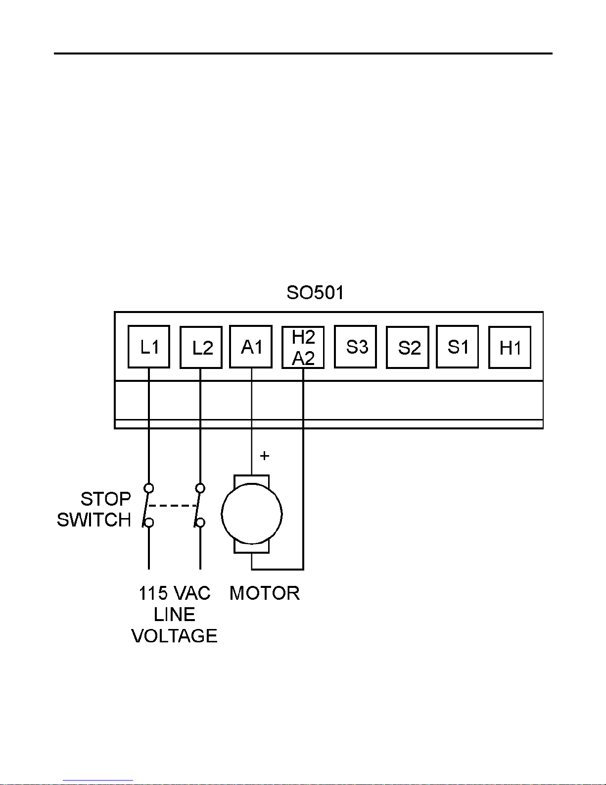
Power connections
Connect the AC line power leads to SO501 terminals L1 and
L2, or to a double-throw, single-pole master power switch as
shown in Figure 4 (recommended).
10 Installation
Figure 4. Power and Motor Connections
250-0146r3_readers_spreads.qxd 7/10/01 4:40 PM Page 10
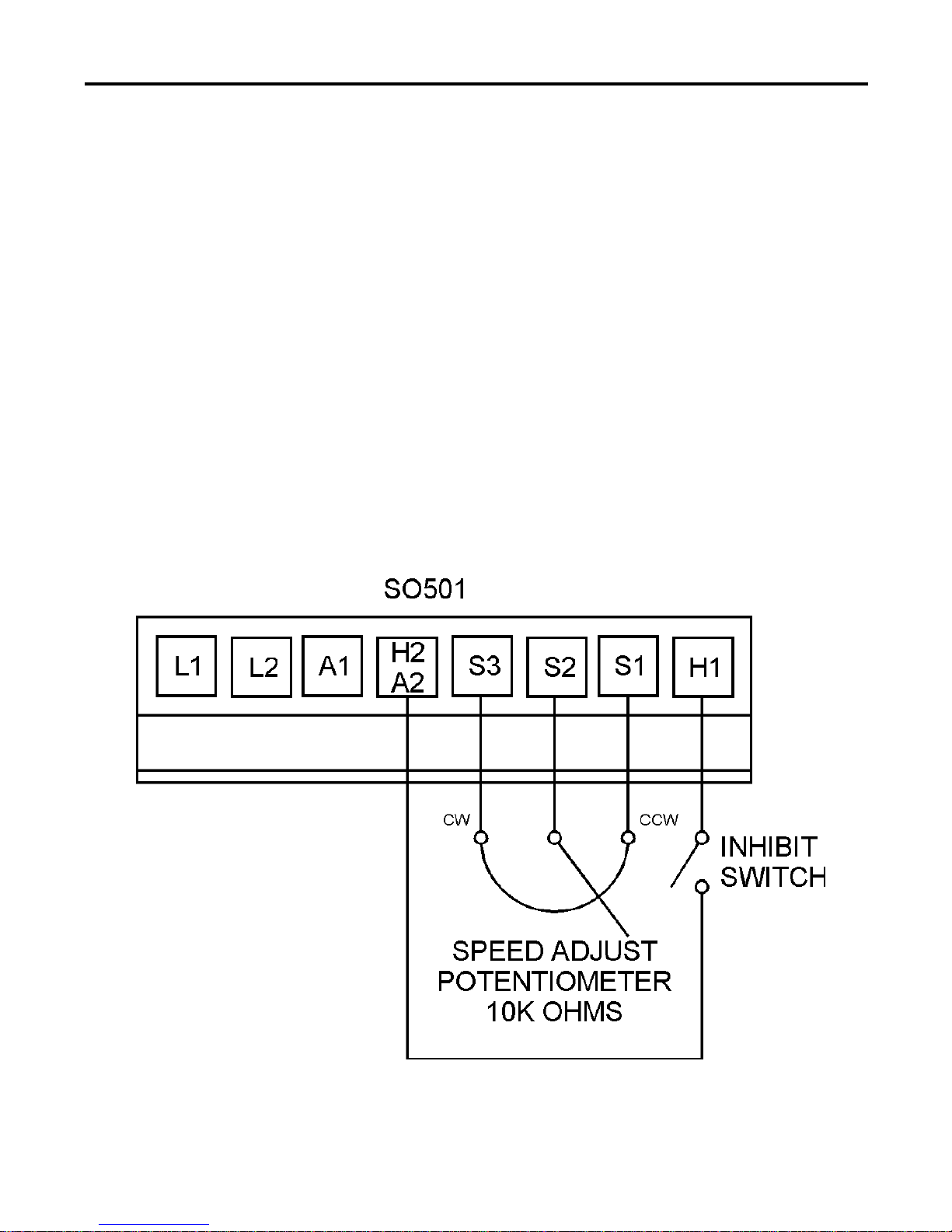
11Installation
Figure 5. Signal and Optional Switch Connections
Signal and optional switch connections
Speed adjust potentiometer
Connect the speed adjust potentiometer to terminals S1, S2 and
S3 of connector SO501 as shown in Figure 5. The CW
terminal must be connected to S3.
Inhibit switch
Connect a single-pole, single-throw switch to the H1 and
H2/A2 terminals of SO501 (Figure 5). Close the switch to
coast the motor to minimum speed; open the switch to
accelerate to set speed.
250-0146r3_readers_spreads.qxd 7/10/01 4:40 PM Page 11
12 Installation
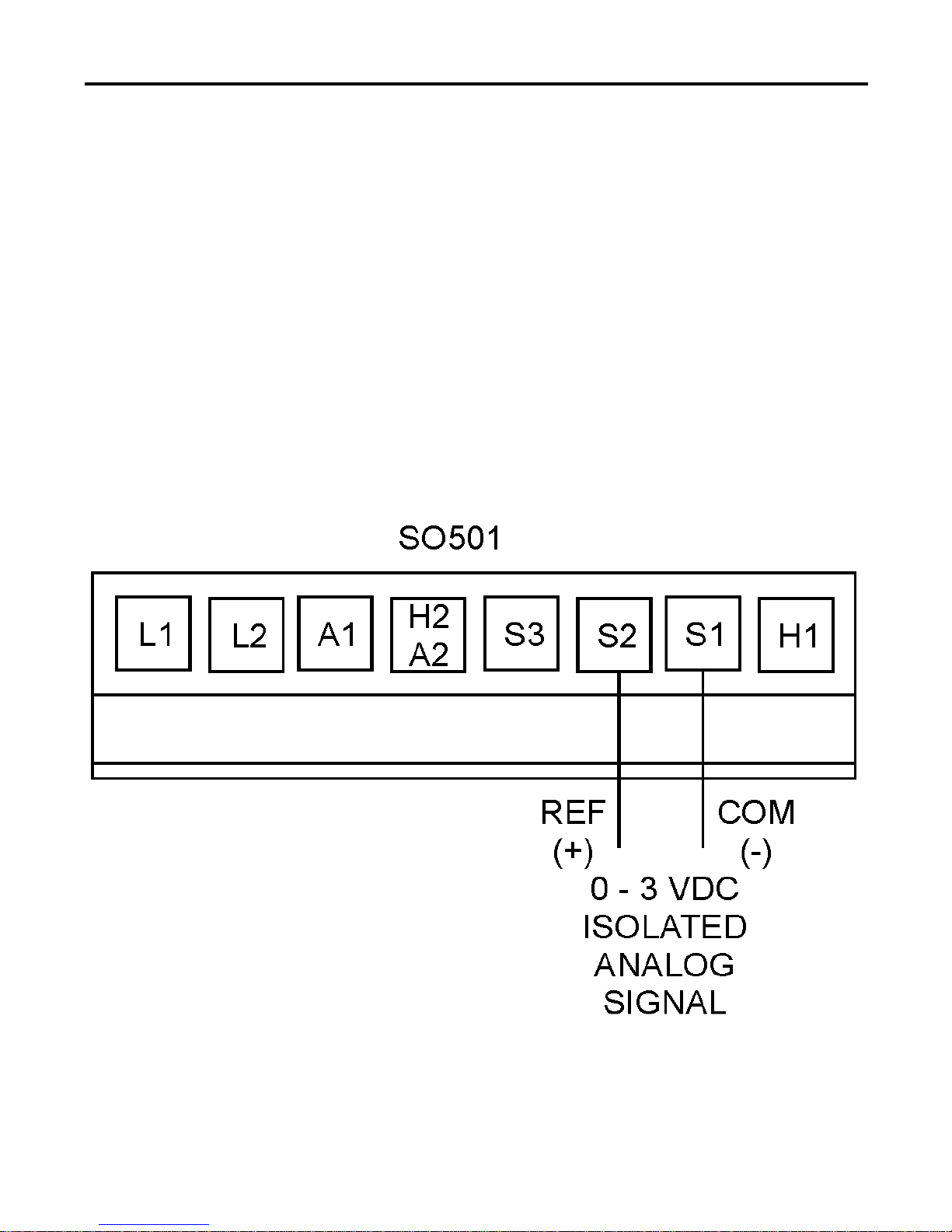
Figure 6. Voltage Follower Connections
Voltage follower
Instead of using a speed adjust potentiometer, the drive may be
wiredtofollowa0-3VDCanalog input voltage signal that is
isolated from earth ground (Figure 6). Connect the signal input
(+) to S2. Connect the signal common (–) to S1. Make no
connection to S3.
A potentiometer can be used to scale the analog input voltage.
An interface device, such as Minarik model PCM4, may be
used to scale and isolate an analog input voltage.
250-0146r3_readers_spreads.qxd 7/10/01 4:40 PM Page 12

13
Before applying power
• Verify that no conductive material is present on the printed
circuit board.
• Verify that the AC supply is properly balanced.
Drive startup and shutdown
1. Set the reference signal or speed adjust potentiometer to
minimum speed.
2. Ensure that the INHIBIT switch is set to the RUN (open)
position.
2. Apply AC line voltage.
3. Slowly turn the speed adjust potentiometer or increase the
reference signal until the desired speed is reached.
Warning
Dangerous voltages exist on the drive when it is powered.
BE ALERT. High voltages can cause serious or fatal
injury.
Operation
250-0146r3_readers_spreads.qxd 7/10/01 4:40 PM Page 13

14 Operation
Warning
For frequent starts and stops, use dynamic braking, inhibit
mode, or decelerating to a stop (shorting S2 to S1). Do
not use any of these methods for emergency stopping.
They may not stop a drive that is malfunctioning.
Removing AC line power (both L1 and L2) is the only
acceptable method for emergency stopping.
Minarik strongly recommends the installation of an
emergency stop switch for chassis drives. The switch
contacts should be rated at a minimum of 250 volts and
200% of maximum motor current.
To shut down the drive:
To decelerate the motor from set speed to a stop, set the speed
adjust potentiometer to zero speed. To coast the motor from set
speed to a stop, remove AC line voltage from the drive or short
SO501 terminals H1 and H2.
Reversing
Refer to Application Notes (page 25) for reversing options, or
contact your Minarik sales representative.
Starting and Stopping Methods
250-0146r3_readers_spreads.qxd 7/10/01 4:40 PM Page 14
This manual suits for next models
1
Table of contents
Other Minarik Inverter manuals


Popular Inverter manuals by other brands

Tripp Lite
Tripp Lite UT Series owner's manual

MQ Power
MQ Power WhisperWatt DCA250SSI Specifications

Go Power
Go Power GP-ISW-400 quick start guide

OutBack Power
OutBack Power Radian GS8048A Operator's manual

GOAL ZERO
GOAL ZERO YETI 1250 user guide

Delta
Delta SOLIVIA 10 EU T4 TL Operation and installation manual

Delta
Delta RPI M6A installation guide

Tripp Lite
Tripp Lite Utility/ Work Truck DC-to-AC Inverters owner's manual

Sofar solar
Sofar solar ME 5KTL-3PH user manual

DualLite
DualLite LG125S Installation instructions and user manual

Delta
Delta RPI H3A user manual

SignalFire
SignalFire Repeater Series Interface manual


