SignalFire Repeater Series User manual

1
SignalFire Telemetry
Rev 2.0
Interface Manual
Solar Powered Repeater
SignalFire Model: Repeater-xxxx
The SignalFire Solar powered repeater is a stand-alone device with the following features:
-Long Range (2-3 miles) 500mW Radio
-Integrated high gain omni-directional antenna or remote antenna options
-Automatically forwards messages from other SignalFire Nodes
-Mounting bracket and U-Bolts to mount to a vertical or horizontal pole
-AES 128bit Encryption

2
SignalFire Telemetry
Rev 2.0
Specifications
Overall Size
14” tall ×12” wide ×8” deep (not including antenna
Power Source
Integrated HC Solar system includes 4W solar panel, integrated charger and
9Ah battery pack
Temperature Rating
-40°C to +85°C
Radio
Antenna
500mW 902-928MHz Ism Band, FHSS radio
Integrated omni-directional antenna or N-Connector for external SignalFire
antennas
Compliance
FCC/IC Certified. FCC ID: W8V-SFTS500, IC: 8373A-SFTS500
3
SignalFire Telemetry
Rev 2.0
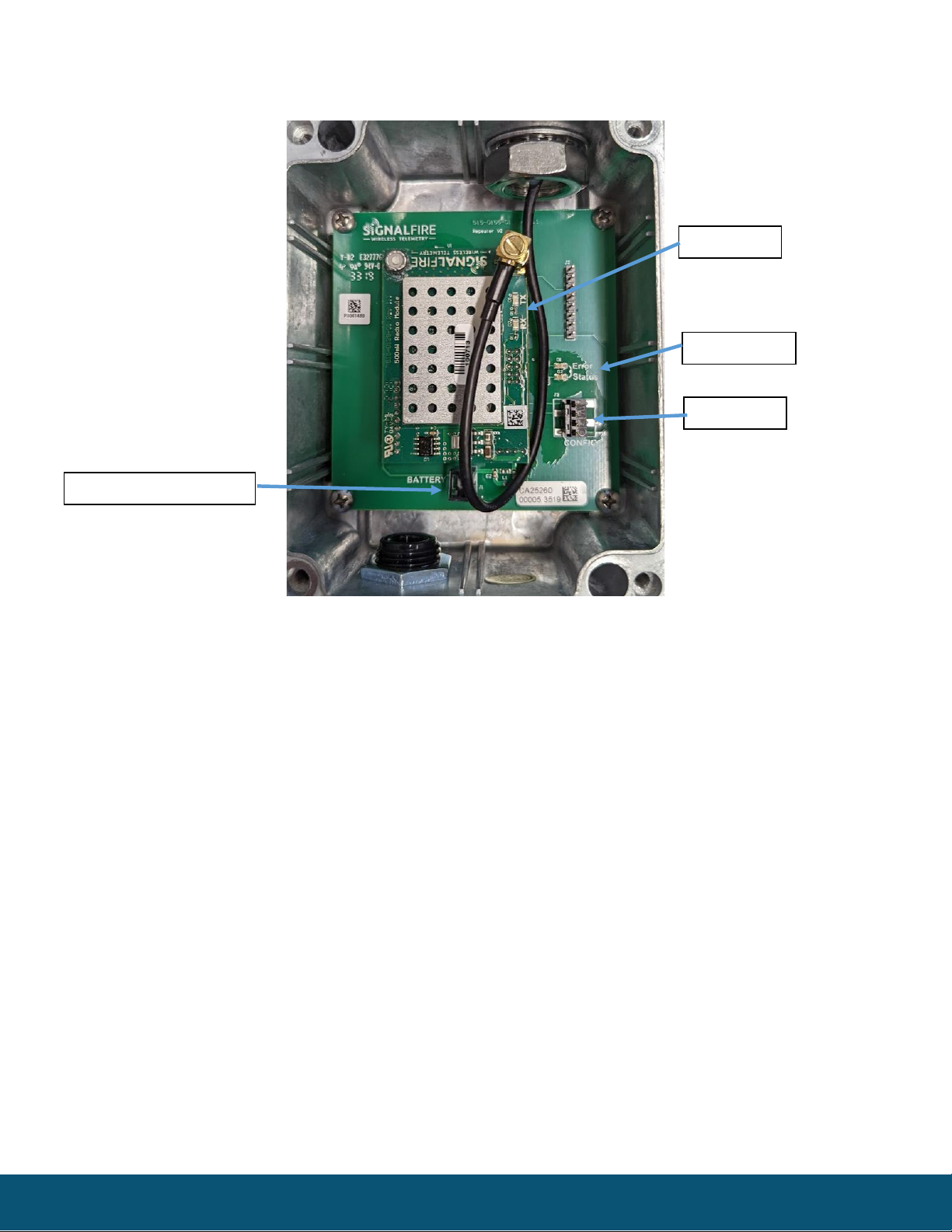
Connections and Components
Radio LEDs
-The Radio TX LED (green) flashes each time a radio packet is sent. This LED will blink rapidly while
searching for the radio network.
-The Radio RX LED (red) blinks on each received radio packet.
Status LEDs
-The Active LED (green) will blink at boot up and will blink rapidly when the sensor is being powered and
read.
-The ERROR LED (red) will blink to indicate an error condition.
Solar Battery Connector
-Run the power cable from the solar system through the cord grip and plug into this connector. Tighten
cord grip to ensure water tight seal
Configuration Port
-Connect a SignalFire USB-Serial-4PIN cable to this port to configure the Repeater with the SignalFire
ToolKit software
Radio LEDs
Solar Battery Connector
Config Port
Status LEDs

4
SignalFire Telemetry
Rev 2.0
Setup
The Repeater must be configured for correct operation before being fielded. The configurable items include:
-Radio Network/Group selection
-Radio encryption setting
-Unique Modbus ID
-Node Name (optional)
All settings are made using the SignalFire Toolkit PC application and a serial programming cable (USB-Serial-
4PIN).
Using the SignalFire Toolkit
The SignalFire Toolkit application can be downloaded at www.signal-fire.com/customer. After installation,
launch the software and the main toolkit window will open:
Select the COM port associated with the Repeater and click “Auto-Detect Device on COM Port.” This will open
the device configuration window, where all device settings can be configured.
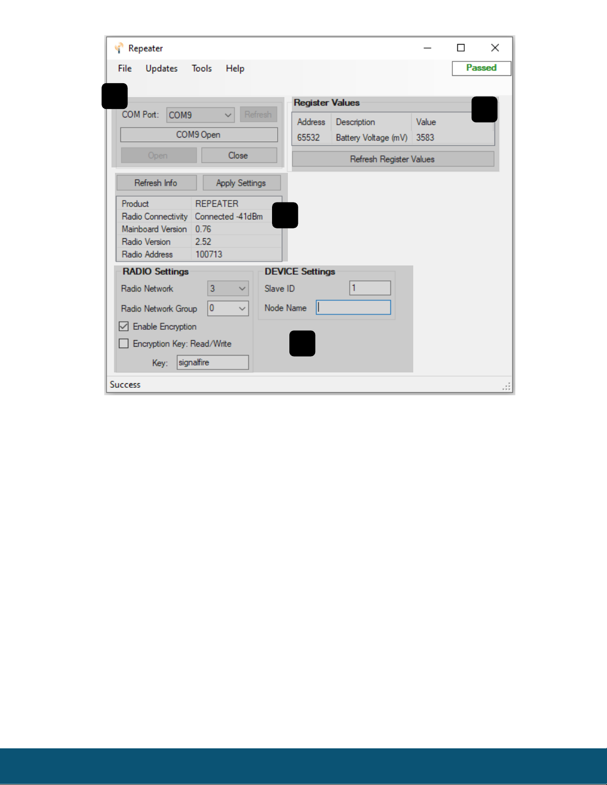
5
SignalFire Telemetry
Rev 2.0
❶
COM Settings
❹
Register Values
❷
Node Information
❸
Radio and Device Settings
1
2
3
4
6
SignalFire Telemetry
Rev 2.0
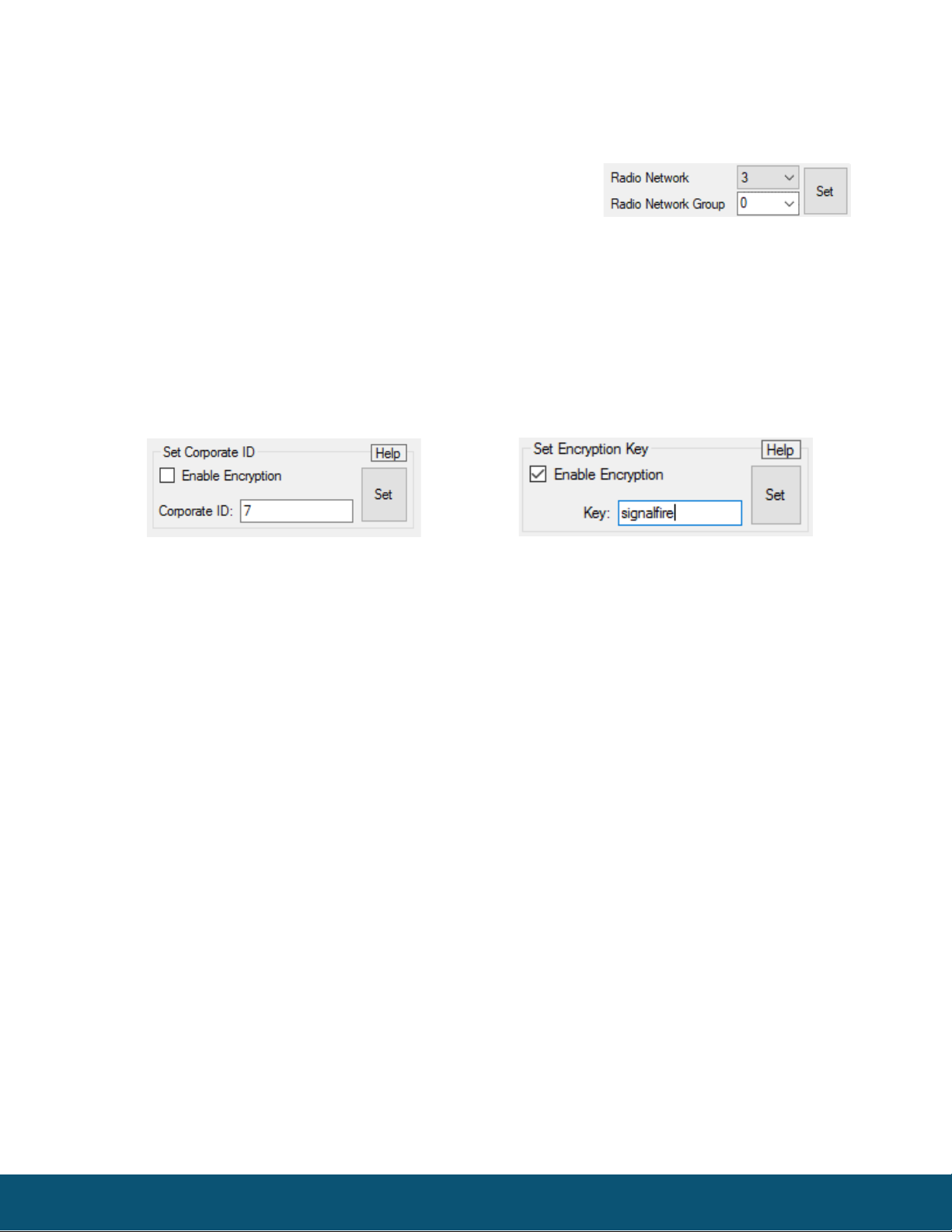
Network Setting
The network is set using the SignalFire Toolkit. The network, network group, and corporate ID/encryption key
settings must match those of the gateway for them to communicate.
Encryption
To protect your over-the-air data and prevent tampering, SignalFire networks come with encryption. Legacy
products use a Corporate ID, but can be switched over to use an encryption key if the firmware and ToolKit are
up to date.
To set up a legacy Sentinel to use encryption, click the checkbox labeled Enable Encryption inside the Set
Corporate ID box. All newer Sentinels come with this option enabled with “signalfire” as the default encryption
key.
The box will then change into a Set Encryption Key box, and it will prompt instead for the encryption key you
would like to use. Note that keys may not contain spaces or angle brackets. Enter it and then press Set. If you are
setting up a new network, you will need to set the encryption key on all of your devices. If you are adding a
Sentinel to a legacy network, you can simply set the Corporate ID without clicking the Enable Encryption box,
and it will remain compatible with the older system.
Slave ID
The Repeater must be configured with a unique (to the Gateway) Modbus Slave ID. The repeater will
used this ID to report its status registers to the Gateway
Node Name
This optional field will be reported to the Gateway and will be visible with the SignalFire Toolkit and
can be used to identify the Repeater.
Operating Mode
The Repeater will automatically act as a repeater in the SignalFire network and forward messages for
other devices. No configuration of the meshing is needed. The repeater also reports to the Gateway
once every 5-minues and sends it status registers including solar battery voltage. The solar system
will provide 7-days of autonomy on a fully charged battery.
Encryption Enabled
Corporate ID

7
SignalFire Telemetry
Rev 2.0
Mounting and Care
Both the repeater box and the solar panel should be mounted to a pole using the supplied bracket
and U-Bolts. The repeater should be mounted as high as practical for best radio range. The repeater
should be mounted so that the antenna extends above the pole into free space. Route the power
cable into the Repeater enclosure through the cord grip and plug into the battery connector. Tighten
the cord grip to ensure a water-tight seal.
Mount the solar panel with a clear view of the southern sky.

8
SignalFire Telemetry
Rev 2.0
Remote Modbus Register Mapping
In addition to forwarding messages for other devices, the Repeater also reports status registers to the
SignalFire Telemetry Modbus Gateway. The data that is sent to the gateway is available at the gateway in
registers where it can then be read by a Modbus RTU.
This data is accessible at the same Slave ID that the Repeater is configured for
Register Map
Register
Number
Register
Address
(Offset)
Description
49988
9987 or 65524
Major revision number for the mainboard
49989
9988 or 65525
Minor revision number for the mainboard
49990
9989 or 65526
Major revision number for the radio
49991
9990 or 65527
Minor revision number for the radio
49992
9991 or 65528
High 16 bits of SFTS node address
49993
9992 or 65529
Low 16 bits of SFTS node address (the radio ID)
49994
9993 or 65530
Slave ID readback
49995
9994 or 65531
Received signal strength of last packet from the slave
49996
9995 or 65532
Battery voltage of the Modbus client, in millivolts
49997
9996 or 65533
Minutes until this slave will time out, unless new data is received
49998
9997 or 65534
Number of registers cached for this slave device
49999
9998 or 65535
Remote device type which is 80 for the Repeater
Technical Support and Contact Information
SignalFire Telemetry
140 Locke Dr, Suite B
Marlborough, MA 01752
(978) 212-2868
support@signal-fire.com

9
SignalFire Telemetry
Rev 2.0
Revision History
Revision
Date
Changes/Updates
2.0
12/16/21
Updated for current repeater hardware revision. Reformatting

10
SignalFire Telemetry
Rev 2.0
APPENDIX - FCC and IC Statements
Changes or modifications not expressly approved by SignalFire Telemetry, Inc could void the user’s
authority to operate the equipment.
This device complies with Part 15 of the FCC Rules. Operation is subject to the following two conditions:
(1) this device may not cause harmful interference, and (2) this device must accept any interference received,
including interference that may cause undesired operation.
This equipment has been tested and found to comply with the limits for a Class B digital device, pursuant to
Part 15 of the FCC Rules. These limits are designed to provide reasonable protection against harmful
interference in a residential installation. This equipment generates, uses and can radiate radio frequency energy
and, if not installed and used in accordance with the instructions, may cause harmful interference to radio
communications. However, there is no guarantee that interference will not occur in a particular installation. If
this equipment does cause harmful interference to radio or television reception, which can be determined by
turning the equipment off and on, the user is encouraged to try to correct the interference by one of the
following measures:
-- Reorient or relocate the receiving antenna.
-- Increase the separation between the equipment and receiver.
-- Connect the equipment into an outlet on a circuit different from that to which the receiver is connected.
-- Consult the dealer or an experienced radio/TV technician for help.
This device has been designed to operate with the antennas listed below and having a maximum gain of 5.8
dBi. Antennas having a gain greater than 5.8 dBi are strictly prohibited for use with this device. The required
antenna impedance is 50 ohms.
ANT-WP-X-X
To reduce potential radio interference to other users, the antenna type and its gain should be so chosen that
the equivalent isotopically radiated power (e.i.r.p.) is not more than that permitted for successful
communication.
To comply with FCC’s and IC’s RF radiation exposure requirements, the antenna(s) used for this transmitter
must be installed such that a minimum separation distance of 20cm is maintained between the radiator
(antenna) & user’s/nearby person’s body at all times and must not be co-located or operating in conjunction
with any other antenna or transmitter.
This device complies with Industry Canada’s license-exempt RSSs. Operation is subject to the following two
conditions:(1) This device may not cause interference; and (2) This device must accept any interference,
including interference that may cause undesired operation of the device.
Le présent appareil est conforme aux CNR d'Industrie Canada applicables aux appareils radio exempts de
licence. L'exploitation est autorisée aux deux conditions suivantes : (1) l'appareil ne doit pas produire de
brouillage, et (2) l'appareil doit accepter tout brouillage radioélectrique subi, même si le brouillage est
susceptible d'en compromettre le fonctionnement.
Table of contents
Popular Inverter manuals by other brands


IO-Power Technology
IO-Power Technology Cloudy-Solar Collection IOP-USSS-12V1224-OA... user manual

Samlex Europe
Samlex Europe SWI 400 manual

Goodwe
Goodwe SDT G2 Series Quick installation guide

movie-intercom
movie-intercom LFX Master DMX user manual

Energenie
Energenie EG-PWC-PS2000-01 manual

CyberPower
CyberPower CPS600E-DE user manual


