Minarik MM23000 Series User manual

SCR, Adjustable Speed Drives
for DC Brush Motors
MM23000
Series
Users Manual

Copyright 2002 by
Minarik Corporation
All rights reserved. No part of this manual may be reproduced or transmitted in any
form without written permission from Minarik Corporation. The information and
technical data in this manual are subject to change without notice. Minarik
Corporation and its Divisions make no warranty of any kind with respect to this
material, including, but not limited to, the implied warranties of its merchantability
and fitness for a given purpose. Minarik Corporation and its Divisions assume no
responsibility for any errors that may appear in this manual and make no
commitment to update or to keep current the information in this manual. MVD032202
Printed in the United States of America.

i
Safety Warnings
•This symbol denotes an important safety tip or warning.
Please read these instructions carefully before performing
any of the procedures contained in this manual.
•DO NOT INSTALL, REMOVE, OR REWIRE THIS EQUIPMENT
WITH POWER APPLIED. Have a qualified electrical technician
install, adjust and service this equipment. Follow the National
Electrical Code and all other applicable electrical and safety
codes, including the provisions of the Occupational Safety and
Health Act (OSHA), when installing equipment.
•Reduce the chance of an electrical fire, shock, or explosion by
proper grounding, over-current protection, thermal protection,
and enclosure. Follow sound maintenance procedures.
It is possible for a drive to run at full speed as a result
of a component failure. Minarik strongly recommends the
installation of a master switch in the main power input to
stop the drive in an emergency.
Circuit potentials are at 115 VAC or 230 VAC above earth
ground. Avoid direct contact with the printed circuit board or
with circuit elements to prevent the risk of serious injury or
fatality. Use a non-metallic screwdriver for adjusting the
calibration trimpots. Use approved personal protective
equipment and insulated tools if working on this drive with
power applied.

ii
Contents
Safety Warnings . . . . . . . . . . . . . . . . . . . . . . . . . . . . . . . . . . . . . . . . . . . . . . .i
Specifications . . . . . . . . . . . . . . . . . . . . . . . . . . . . . . . . . . . . . . . . . . . . . . . .1
Specifications (Continued) . . . . . . . . . . . . . . . . . . . . . . . . . . . . . . . . . . . . . . .2
Suffix Definitions . . . . . . . . . . . . . . . . . . . . . . . . . . . . . . . . . . . . . . . . . . . . .2
Dimensions . . . . . . . . . . . . . . . . . . . . . . . . . . . . . . . . . . . . . . . . . . . . . . . . . . .3
Installation . . . . . . . . . . . . . . . . . . . . . . . . . . . . . . . . . . . . . . . . . . . . . . . . . . .11
Chassis drives . . . . . . . . . . . . . . . . . . . . . . . . . . . . . . . . . . . . . . . . . . . . .11
Mounting . . . . . . . . . . . . . . . . . . . . . . . . . . . . . . . . . . . . . . . . . . . . . . . .11
Wiring . . . . . . . . . . . . . . . . . . . . . . . . . . . . . . . . . . . . . . . . . . . . . . . . . .12
Shielding guidelines . . . . . . . . . . . . . . . . . . . . . . . . . . . . . . . . . . . . . . . .13
Heat sinking . . . . . . . . . . . . . . . . . . . . . . . . . . . . . . . . . . . . . . . . . . . . .14
Quick-disconnect terminal block (C-Q drives only) . . . . . . . . . . . . . . . . .15
Speed adjust potentiometer . . . . . . . . . . . . . . . . . . . . . . . . . . . . . . . . . .16
Chassis drive connections . . . . . . . . . . . . . . . . . . . . . . . . . . . . . . . . . . .17
Power, fuse and motor connections . . . . . . . . . . . . . . . . . . . . . . . . . . . .17
Voltage follower . . . . . . . . . . . . . . . . . . . . . . . . . . . . . . . . . . . . . . . . . . .23
Cased drives . . . . . . . . . . . . . . . . . . . . . . . . . . . . . . . . . . . . . . . . . . . . . . .24
Mounting (NEMA 1 enclosures) . . . . . . . . . . . . . . . . . . . . . . . . . . . . . . .24
Mounting (NEMA 4X and NEMA 12 enclosures) . . . . . . . . . . . . . . . . . .25
Heat sinking . . . . . . . . . . . . . . . . . . . . . . . . . . . . . . . . . . . . . . . . . . . . .26
Line fusing . . . . . . . . . . . . . . . . . . . . . . . . . . . . . . . . . . . . . . . . . . . . . .26
Connections . . . . . . . . . . . . . . . . . . . . . . . . . . . . . . . . . . . . . . . . . . . . .27
Current limit LED (C models only) . . . . . . . . . . . . . . . . . . . . . . . . . . . . . . .30
Meter header block (cased C models only) . . . . . . . . . . . . . . . . . . . . . . . . .30
MM23001C-Q, MM23071, and MM23072 diagnostic LEDs . . . . . . . . . . . . .31
Operation . . . . . . . . . . . . . . . . . . . . . . . . . . . . . . . . . . . . . . . . . . . . . . . . . . . .32
Before applying power . . . . . . . . . . . . . . . . . . . . . . . . . . . . . . . . . . . . . . . .32
Voltage select switches . . . . . . . . . . . . . . . . . . . . . . . . . . . . . . . . . . . . . . .33
Input voltage select (SW501) . . . . . . . . . . . . . . . . . . . . . . . . . . . . . . . . .33
Armature voltage select (SW502) . . . . . . . . . . . . . . . . . . . . . . . . . . . . .33
Startup . . . . . . . . . . . . . . . . . . . . . . . . . . . . . . . . . . . . . . . . . . . . . . . . . . .34
MM23001, MM23011, MM23071, and MM23072 . . . . . . . . . . . . . . . . . .34

MM23101, MM23111, MM23401, and MM23411 . . . . . . . . . . . . . . . . . .34
MM23201 and MM23211 . . . . . . . . . . . . . . . . . . . . . . . . . . . . . . . . . . . .35
MM23501 . . . . . . . . . . . . . . . . . . . . . . . . . . . . . . . . . . . . . . . . . . . . . . . .36
Starting and stopping methods . . . . . . . . . . . . . . . . . . . . . . . . . . . . . . . . . .37
Line starting and line stopping . . . . . . . . . . . . . . . . . . . . . . . . . . . . . . . .37
Inhibit terminals . . . . . . . . . . . . . . . . . . . . . . . . . . . . . . . . . . . . . . . . . . .38
Decelerating to minimum speed . . . . . . . . . . . . . . . . . . . . . . . . . . . . . . .39
Dynamic braking . . . . . . . . . . . . . . . . . . . . . . . . . . . . . . . . . . . . . . . . . . .40
Calibration . . . . . . . . . . . . . . . . . . . . . . . . . . . . . . . . . . . . . . . . . . . . . . . . . . .42
MINIMUM SPEED (MIN SPD) . . . . . . . . . . . . . . . . . . . . . . . . . . . . . . . . . .43
MAXIMUM SPEED (MAX SPD) . . . . . . . . . . . . . . . . . . . . . . . . . . . . . . . . .43
TORQUE . . . . . . . . . . . . . . . . . . . . . . . . . . . . . . . . . . . . . . . . . . . . . . . . . .44
IR COMPENSATION (IR COMP) . . . . . . . . . . . . . . . . . . . . . . . . . . . . . . . .45
ACCELERATION (ACCEL) . . . . . . . . . . . . . . . . . . . . . . . . . . . . . . . . . . . .47
DECELERATION (DECEL) . . . . . . . . . . . . . . . . . . . . . . . . . . . . . . . . . . . .48
Application Notes . . . . . . . . . . . . . . . . . . . . . . . . . . . . . . . . . . . . . . . . . . . . .49
Multiple fixed speeds . . . . . . . . . . . . . . . . . . . . . . . . . . . . . . . . . . . . . . . . .49
Adjustable speeds using potentiometers in series . . . . . . . . . . . . . . . . . . . .50
Independent adjustable speeds . . . . . . . . . . . . . . . . . . . . . . . . . . . . . . . . .51
RUN/JOG switch . . . . . . . . . . . . . . . . . . . . . . . . . . . . . . . . . . . . . . . . . . . .52
RUN/JOG switch option #1 . . . . . . . . . . . . . . . . . . . . . . . . . . . . . . . . . .52
RUN/JOG switch option #2 . . . . . . . . . . . . . . . . . . . . . . . . . . . . . . . . . .53
Leader-follower application . . . . . . . . . . . . . . . . . . . . . . . . . . . . . . . . . . . .54
Single speed potentiometer control of multiple drives . . . . . . . . . . . . . . . . .55
Reversing . . . . . . . . . . . . . . . . . . . . . . . . . . . . . . . . . . . . . . . . . . . . . . . . .56
Reversing with a DIGI-LOK controller . . . . . . . . . . . . . . . . . . . . . . . . . . . . .57
Troubleshooting . . . . . . . . . . . . . . . . . . . . . . . . . . . . . . . . . . . . . . . . . . . . . .58
Before troubleshooting . . . . . . . . . . . . . . . . . . . . . . . . . . . . . . . . . . . . . . . .58
Replacement Parts . . . . . . . . . . . . . . . . . . . . . . . . . . . . . . . . . . . . . . . . . .66
CE Compliance . . . . . . . . . . . . . . . . . . . . . . . . . . . . . . . . . . . . . . . . . . . . . . .68
Line filters . . . . . . . . . . . . . . . . . . . . . . . . . . . . . . . . . . . . . . . . . . . . . . . . .69
Armature filters . . . . . . . . . . . . . . . . . . . . . . . . . . . . . . . . . . . . . . . . . . . . .70
Unconditional Warranty . . . . . . . . . . . . . . . . . . . . . . . . . . .inside back cover
iii

iv
Illustrations
Figure 1. MM23001 and MM23011 Dimensions . . . . . . . . . . . . . . . . .3
Figure 2. MM23001C-Q and MM23011C-Q Dimensions . . . . . . . . . .4
Figure 3. MM23101 and MM23111 Dimensions . . . . . . . . . . . . . . . . .5
Figure 4. MM23201 and MM23211 Dimensions . . . . . . . . . . . . . . . . .6
Figure 5. MM23401 and MM23411 Dimensions . . . . . . . . . . . . . . . . .7
Figure 6. MM23501 Dimensions . . . . . . . . . . . . . . . . . . . . . . . . . . . .8
Figure 7. MM23071 and MM23072 Dimensions . . . . . . . . . . . . . . . .9
Figure 8. Heat Sink Dimensions . . . . . . . . . . . . . . . . . . . . . . . . . . .10
Figure 9. Quick-Disconnect Terminal Block . . . . . . . . . . . . . . . . . .15
Figure 10. Speed Adjust Potentiometer . . . . . . . . . . . . . . . . . . . . . .16
Figure 11. Chassis Drive Connections . . . . . . . . . . . . . . . . . . . . . . .21
Figure 12. MM23201C-Q and MM23011C-Q Connections . . . . . . . .22
Figure 13. Voltage Follower Connections . . . . . . . . . . . . . . . . . . . .23
Figure 14. Cased Drive Connections . . . . . . . . . . . . . . . . . . . . . . . .29
Figure 15. Voltage Switches . . . . . . . . . . . . . . . . . . . . . . . . . . . . . .33
Figure 16. INHIBIT Terminals . . . . . . . . . . . . . . . . . . . . . . . . . . . . .38
Figure 17. Run/Decelerate to Minimum Speed Switch . . . . . . . . . . .39
Figure 18. Dynamic Brake Connection . . . . . . . . . . . . . . . . . . . . . .41
Figure 19. Recommended Torque and IR COMP Settings . . . . . . .46
Figure 20. Multiple Fixed Speeds . . . . . . . . . . . . . . . . . . . . . . . . . .49
Figure 21. Adjustable Fixed Speeds Using
Potentiometers in Series . . . . . . . . . . . . . . . . . . . . . . . .50
Figure 22. Independent Adjustable Speeds . . . . . . . . . . . . . . . . . . .51

v
Figure 23. RUN/JOG Switch Connection to Inhibit Plug (Option #1) .52
Figure 24. RUN/JOG Switch Connection to
Speed Adjust Potentiometer (Option #2) . . . . . . . . . . . . .53
Figure 25. Leader-Follower Application . . . . . . . . . . . . . . . . . . . . . .54
Figure 26. Single Speed Potentiometer Control of Multiple Drives . .55
Figure 27. Reversing Circuit Connection . . . . . . . . . . . . . . . . . . . . .56
Figure 28. Reversing with a DLC600 . . . . . . . . . . . . . . . . . . . . . . . .57
FIgure 29. MM23000 Series Block Diagram . . . . . . . . . . . . . . . . . .62
FIgure 30. MM23101, MM23111, MM23401 and MM23411
Terminal Block Connections . . . . . . . . . . . . . . . . . . . . . .63
FIgure 31. MM23201 and MM23211 Terminal Block Connections . .64
Figure 32. MM23501 Terminal Block Connections . . . . . . . . . . . . . .65

vi
Tables
Table 1. Recommended Line Fuse Sizes . . . . . . . . . . . . . . . . . . . .19
Table 2. Field Output Connections . . . . . . . . . . . . . . . . . . . . . . . . .20
Table 3. Field Output Connections . . . . . . . . . . . . . . . . . . . . . . . . .28
Table 4. Minimum Recommended Dynamic Brake Resistor Values .41
Table 5. Replacement Parts . . . . . . . . . . . . . . . . . . . . . . . . . . . . . .66
Table 6. Corcom® Filters . . . . . . . . . . . . . . . . . . . . . . . . . . . . . . . .69
Table 7. Minarik Filters . . . . . . . . . . . . . . . . . . . . . . . . . . . . . . . . . .70

1
Specifications
Max.
Armature HP Range HP Range
Current with 115 VAC with 230 VAC
Model (Amps DC) Applied Applied Style
MM23011 1.5 1/20–1/8 1/10–1/4 Chassis
MM23111 NEMA 1
MM23211 NEMA 1
MM23411 NEMA 4/4X/ 12
MM23072 Chassis
MM23001 † 5.0 1/8–1/2 1/4–1 Chassis
MM23101 ‡ NEMA 1
MM23201 ‡ NEMA 1
MM23071 † Chassis
MM23401 10.0 1/8–1 1/4–2 NEMA 4/4X/12
MM23501 NEMA 4/4X/12
† Double maximum armature current and horsepower when drive is mounted on heat
sink part number 223-0159.
‡ Double maximum armature current and horsepower when drive is mounted on heat
sink part number 223-0174.
AC Line Voltage 115 VAC or 230 VAC ±10%, 50/60 Hz, single phase
Armature Voltage (115 VAC Input) 0–90 VDC
Armature Voltage (230 VAC Input) 0–180 VDC
Form Factor 1.37 at base speed
Field Voltage (115 VAC Input) 50 VDC (F1 to L1); 100 VDC (F1 to F2)
Field Voltage (230 VAC Input) 100 VDC (F1 to L1); 200 VDC (F1 to F2)
Max. Field Current 1 ADC
Accel. Time Range:
for 0–90 VDC Armature Voltage 0.5–11 seconds
for 0–180 VDC Armature Voltage 0.5–22 seconds
Decel. Time Range:
for 0-90 VDC Armature Voltage coast to a stop–13 seconds
for 0–180 VDC Armature Voltage coast to a stop–25 seconds
Analog Input Voltage Range (signal must be isolated; S1 to S2):
for 0–90 VDC Armature Voltage 0–1.4 VDC
for 0–180 VDC Armature Voltage 0–2.8 VDC

2Specifications
Input Impedance (S1 to S2) 100K ohms
Load Regulation 1% base speed or better
Vibration 0.5G max (0–50 Hz)
0.1G max (>50 Hz)
Safety Certification UL Recognized Component, file # E132235
CSA Certified Component, file # LR41380
CE Certificate of Compliance
Ambient Temp. Range (chassis drive) 10°C–55°C
Ambient Temp. Range (cased drive) 10°C–40°C
Suffix Definitions
A: Basic drive
C: Basic drive with current limit LED
C-Q: Basic drive with current limit LED, power LED, and quick-
disconnect terminal block
Note:
•C suffix applies to all models except MM23071 and MM23072.
•MM23071A and MM23072A drives include a current limit and
power LED; trimmer potentiometers (trimpots) are
perpendicular to the PC board.
Specifications (Continued)

3
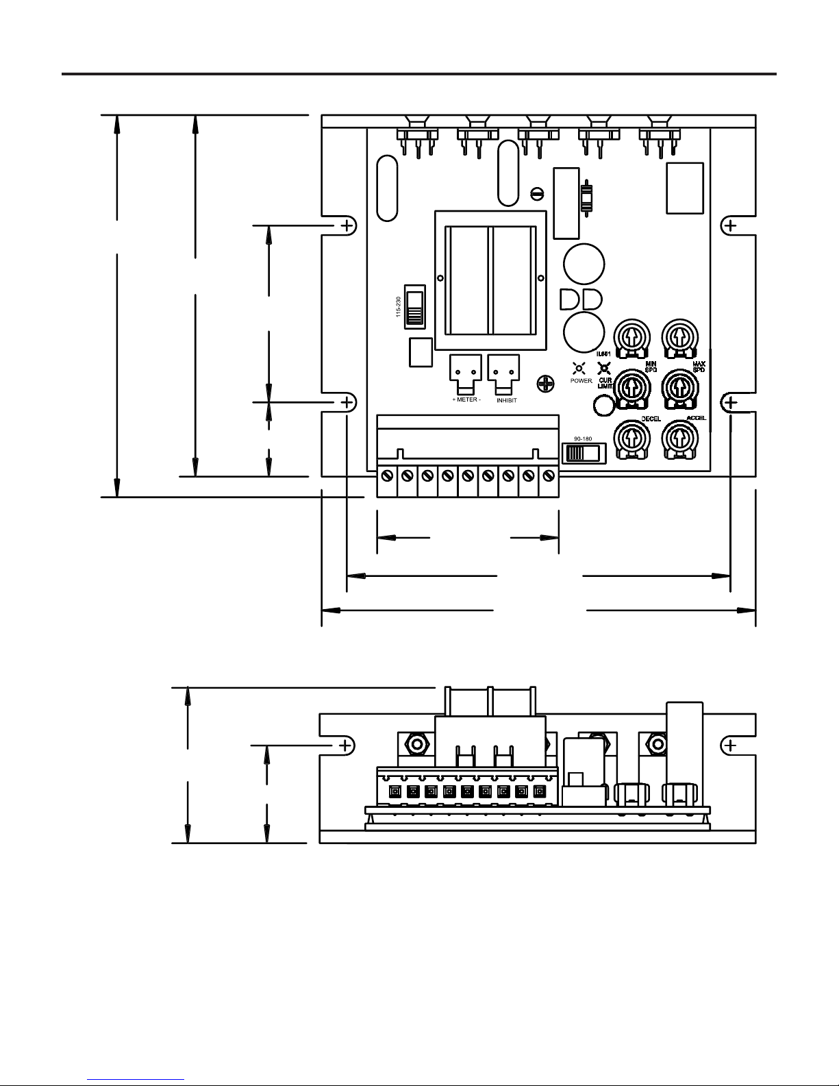
Dimensions
3.80 [97]
0.74 [19]
1.75 [44]
3.58 [91]
1.28 [33]
0.96 [24]
1.60 [41]
0.19 [5]
0.64 [16]
0.19 [5]
4.30 [109]
DECELACCEL
S3
S2
INHIBIT
C504
MIN SPDMAX SPD TORQUE
18090
SW502 IL501
CL
MOV501
L1
L2
F1
MOV503
SW501
F2
SCR501 D501
R502
SO502
+
METER
-
D502
A2
MOV502
D503
A1
IR COMP
IC501
C502
S1
C503
IC502
C501
R501
SCR502
115 230
Figure 1. MM23001 and MM23011 Dimensions
ALL DIMENSIONS IN INCHES [MILLIMETERS]
4Dimensions
Figure 2. MM23001C-Q and MM23011C-Q Dimensions
ALL DIMENSIONS IN INCHES [MILLIMETERS]
IR
CO
MP
TQ
LIMI
T
A1
A2
L1
L2
F1
F2
S
1
S2
S3
0.96 [24]
1
.55
[
39
]
0.74 [ 19]
1
.75
[
44
]
3
.58
[
91
]
3
.95
[
100
]
1
.80
[
46
]
4.30
[
109
]
3
.80
[
97
]
MO
V
503
MO
V
50
1
S
W
50
1
SO502
T50
1
I
L
502
C502
C50
1
IC502
IC50
1
R
50
1
S
W
502
SO503
SO50
1
C504
C503
R
502
MO
V
502
SC
R
502
SC
R
50
1D
50
1D
502
D
503

5
Dimensions
1.79
[45]
5.00
[127]
8.00
[203]
6.00 [125]
2.50
[64]
2.50
[64]
C
L
2.75
[70]
1.25 [32]
2.50
[64]
1.72
[44]
3.46
[88]
TWO 0.88 [22] CONDUIT HOLES
Figure 3. MM23101 and MM23111 Dimensions
ALL DIMENSIONS IN INCHES [MILLIMETERS]

6
ALL DIMENSIONS IN INCHES [MILLIMETERS]
TWO 0.88 [22] KNOCKOUTS
FOUR MOUNTING SLOTS 0.19 INCHES [5 MILLIMETERS] WIDE
Dimensions
1.79
[45]
5.00
[127]
8.00 [203]
6.00 [125]
2.50
[64]
2.50
[64]
C
L
2.75
[70]
1.25 [32]
2.50
[64]
1.72
[44]
3.46 [88]
Figure 4. MM23201 and MM23211 Dimensions
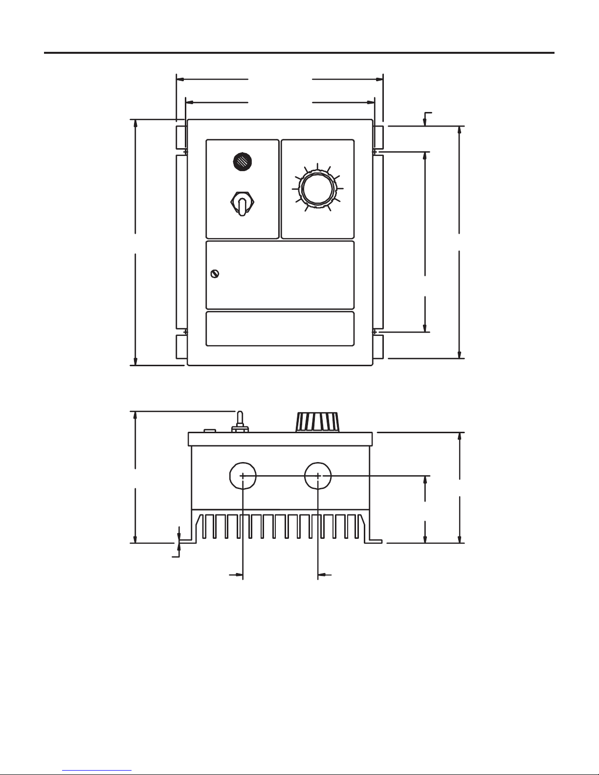
7
Dimensions
6.90 [175]
6.30 [160] 0.87 [22]
7.76 [197]
6.00 [152]
8.20 [208]
3.70 [94]
2.25 [57]
2.50 [64]
0.13 [3]
4.50 [114]
POWER SPEED
Figure 5. MM23401 and MM23411 Dimensions
ALL DIMENSIONS IN INCHES [MILLIMETERS]
TWO 0.88 [22] KNOCKOUTS
FOUR MOUNTING SLOTS 0.19 INCHES [5 MILLIMETERS] WIDE

8Dimensions
6.90 [175]
6.30 [160]
1.37 [35]
7.00 [178]
9.76 [248]
10.20 [259]
4.78 [121]
2.37 [60]
2.50 [64]
0.13 [3]
5.49 [139]
REVERSE FORWARD
BRAKE
POWER SPEED
Figure 6. MM23501 Dimensions
ALL DIMENSIONS IN INCHES [MILLIMETERS]
TWO 0.88 [22] KNOCKOUTS
FOUR MOUNTING SLOTS 0.19 INCHES [5 MILLIMETERS] WIDE
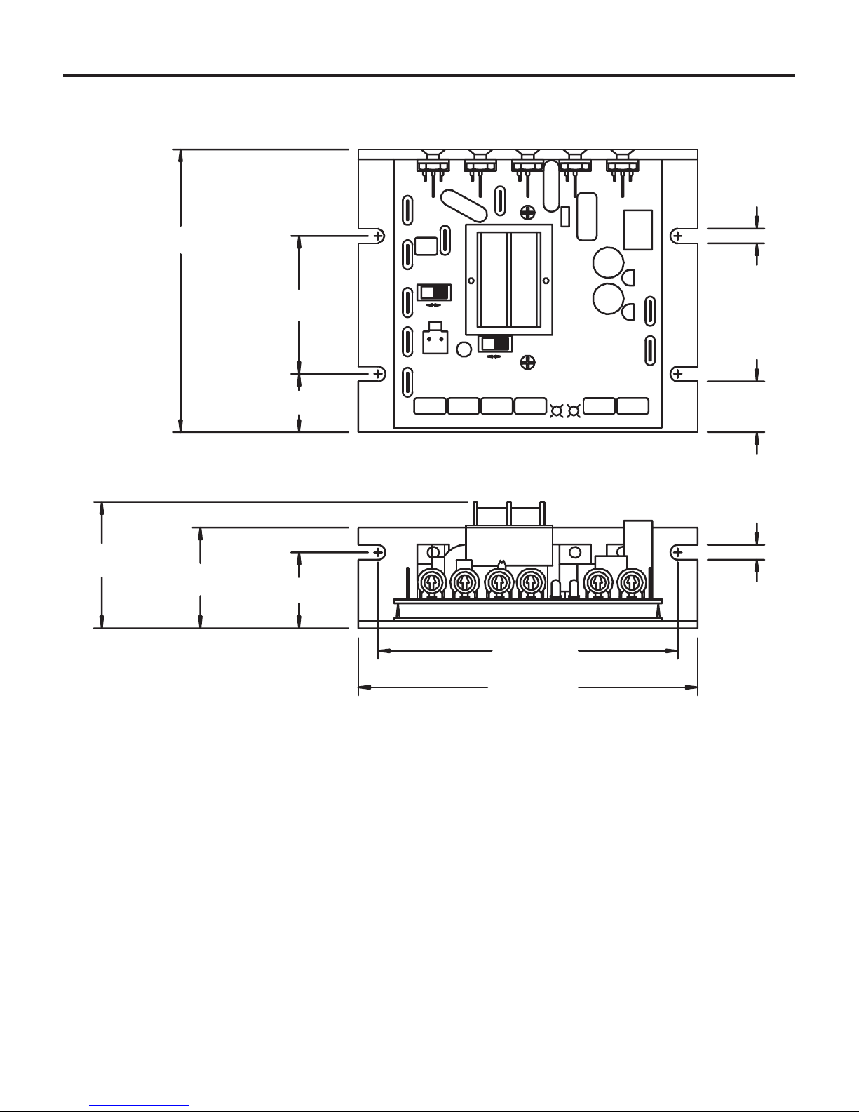
9
ALL DIMENSIONS IN INCHES [MILLIMETERS]
SW501
D503
CUR LIM
L2
C504
P502
DECELACCEL
S2
S3
P501
INHIBIT
IL501IL502
MIN SPDMAX SPD CL PWR
SW502
P504P503
D501
F1
L1
MOV503
F2
MOV501
SCR501
T501
R502
A2
D502
MOV502
IR COMP
S1
P505 P506
C502 IC501
A1
IC502
C501
C503
R501
SCR502
90 180
115 230
3.80 [97]
4.30 [109]
0.19 [5]
0.96 [24]
1.28 [33]
1.60 [41]
0.74 [19]
1.75 [44]
3.58 [91]
0.64 [16]
0.19 [5]
Figure 7. MM23071 and MM23072 Dimensions
Dimensions
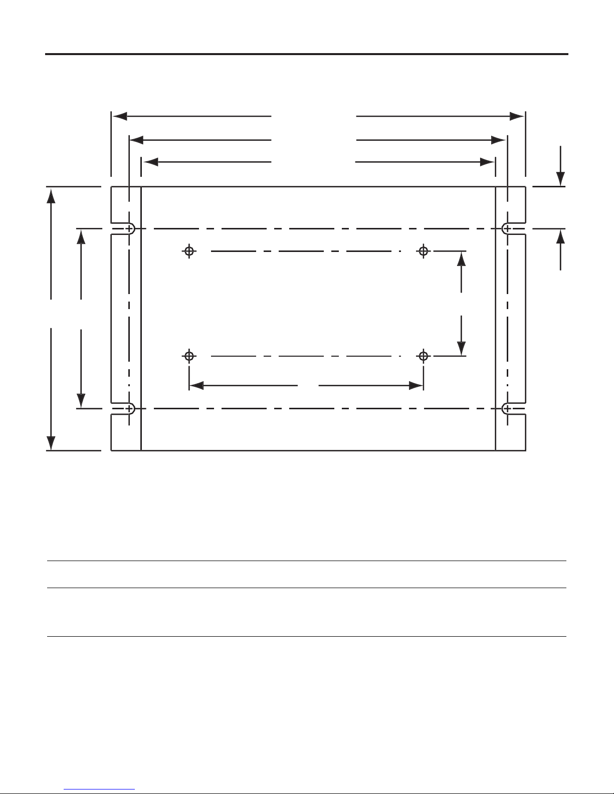
10 Dimensions
PART NO. DIM “A”DIM “B”DIM “C”DIM “D”DIM “E”
223-0159 4.40 [112] 3.00 [76] 0.7 [18] 1.75 [44] 3.90 [100]
223-0174 7.78 [198] 6.00 [152] 0.89 [23] 6.00 [152] 5.35 [136]
Heat sinks sold separately.
Figure 8. Heat Sink Dimensions
MOUNTING SLOTS 0.19 X 0.34 [5 X 9]
ALL DIMENSIONS IN INCHES [MILLIMETERS]
B
A
5
.90
[
150
]
6.30
[
160
]
6.90
[
175
]
E
D
C

11
Chassis drives
Mounting
•Drive components are sensitive to electrostatic fields. Avoid
contact with the circuit board directly. Hold drive by the chassis
only.
•Protect the drive from dirt, moisture, and accidental contact.
•Provide sufficient room for access to the terminal block and
calibration trimpots.
•Mount the drive away from other heat sources. Operate the drive
within the specified ambient operating temperature range.
•Prevent loose connections by avoiding excessive vibration of the
drive.
•Mount drive with its board in either a horizontal or vertical plane.
Six 0.19 inch (5 mm) wide slots in the chassis accept #8 pan
head screws. Fasten either the large base or the narrow flange
of the chassis to the subplate.
•The chassis must be earth grounded. To ground the chassis, use
a star washer beneath the head of at least one of the mounting
screws to penetrate the anodized chassis surface and to reach
bare metal.
Installation
Warning
Do not install, rewire, or remove this control with input
power applied. Doing so may cause fire or serious injury.
Make sure you have read and understood the Safety
Warnings on page i before attempting installation.

12 Installation
•Use 18-24 AWG wire for speed adjust potentiometer wiring. Use
14–16 AWG wire for AC line (L1, L2) and motor (A1 and A2)
wiring.
Wiring
Warning
Do not install, remove, or rewire this equipment with power
applied. Failure to heed this warning may result in fire,
explosion, or serious injury.
Circuit potentials are at 115 or 230 VAC above ground. To
prevent the risk of injury or fatality, avoid direct contact with
the printed circuit board or with circuit elements.
Do not disconnect any of the motor leads from the drive
unless power is removed or the drive is disabled. Opening
any one motor lead may destroy the drive.
Table of contents
Other Minarik Inverter manuals


Popular Inverter manuals by other brands


RCT
RCT Power Storage DC 8.0 manual

GMDE
GMDE GEatom 315KTL user manual

Victron energy
Victron energy C12/1200 Quick installation guide

Autarco
Autarco MX Mark III Series Installation and operation manual

Fuji Electric Europe
Fuji Electric Europe FRENIC-Multi user manual

MPP Solar
MPP Solar PIP8048MAX user manual

Greatwatt Energy
Greatwatt Energy S-700 owner's manual

Xantrex
Xantrex PV100S-480 Planning and installation manual

Hopewind
Hopewind hopeSun Series user manual

Dirty Hand Tools
Dirty Hand Tools 101105 Operation manual

Ingeteam
Ingeteam Ingecon Sun 1Play HF Installation and usage manual

Danfoss
Danfoss TLX+ installation manual