Mini-Itx X600-ITX User manual

Version 1.0
Published December 2023
is device complies with Part 15 of the FCC Rules. Operation is subject to the following
two conditions:
(1) this device may not cause harmful interference, and
(2) this device must accept any interference received, including interference that
may cause undesired operation.
CALIFORNIA, USA ONLY
e Lithium battery adopted on this motherboard contains Perchlorate, a toxic substance
controlled in Perchlorate Best Management Practices (BMP) regulations passed by the
California Legislature. When you discard the Lithium battery in California, USA, please
follow the related regulations in advance.
“Perchlorate Material-special handling may apply, see www.dtsc.ca.gov/hazardouswaste/
perchlorate”

AUSTRALIA ONLY
Our goods come with guarantees that cannot be excluded under the Australian Consumer
Law. You are entitled to a replacement or refund for a major failure and compensation for
any other reasonably foreseeable loss or damage caused by our goods. You are also entitled
to have the goods repaired or replaced if the goods fail to be of acceptable quality and the
failure does not amount to a major failure.
e terms HDMI™ and HDMI High-Denition Multimedia Interface, and the HDMI
logo are trademarks or registered trademarks of HDMI Licensing LLC in the United
States and other countries.

PB 1
English
X600-ITX
Motherboard Layout
USB 3.2 Gen1
USB3_TC_1
Headphone
/ Headset
CPU_FAN1
RoHS
6
DDR5_A2 (64 bit, 288-pin module)
DDR5_A1 (64 bit, 288-pin module)
DDR5_B2 (64 bit, 288-pin module)
DDR5_B1 (64 bit, 288-pin module)
SATA3_A2SATA3_A1
CHA_
FAN1
PANEL1
1
HDLED RESET
PLED PWRBTN
ATX12V1
M.2 WiFi
M.2 PCIe SSD
PCIE1
USB 3. 2 Gen1
T: USB3_1
B: USB3_2
USB 2.0
T: USB_1
B: USB_2
USB 2.0
T: USB_3
B: USB_4
2
12
3
4
9
RJ-45
USB 3.2 Gen1
USB3 34_
USB_5_6
1
10
11
CLRCMOS1
1
1
ATXPWR1
X600-ITX
BIOS
_FB1
HDMI
Top:
LINE IN
Center:
FRONT
Bottom:
MIC IN
DP_2
DP_1
78
CI1
1
5
Top Side View

2 3
English
7
M2_2
Back Side View

2 3
English
X600-ITX
No. Description
1 8 pin 12V Power Connector (ATX12V1)
2 CPU Fan Connector (CPU_FAN1)
3 2 x 288-pin DDR5 DIMM Slots (DDR5_A1, DDR5_B1)
4 2 x 288-pin DDR5 DIMM Slots (DDR5_A2, DDR5_B2)
5 Chassis Intrusion Header (CI1)
6 ATX Power Connector (ATXPWR1)
7 USB 2.0 Header (USB_5_6)
8 SATA3 Connector (SATA3_A1)
9 SATA3 Connector (SATA3_A2)
10 System Panel Header (PANEL1)
11 Chassis Fan Connector (CHA_FAN1)
12 Clear CMOS Jumper (CLRCMOS1)

4 5
English
Front Panel
No. Description No. Description
1Headphone/Headset Jack (AUDIO1) 3 USB 3.2 Gen1 Type-A Ports
2 USB 3.2 Gen1 Type-C Port (USB3_12)
(USB3_TC_1) 4 USB 2.0 Ports (USB_12)
12 3 4

4 5
English
X600-ITX
Rear Panel
No. Description No. Description
1 2.5G LAN RJ-45 Port* 6 BIOS Flashback Button
2 Line In (Light Blue)** 7 USB 2.0 Ports (USB_34)
3 Front Speaker (Lime)** 8 DisplayPort 1.4 (DP_1)
4 Microphone (Pink)** 9 DisplayPort 1.4 (DP_2)
5 USB 3.2 Gen1 Ports (USB3_34) 10 HDMI Port
ACT/LINK LED
SPEED LED
LAN Port
* ere are two LEDs on each LAN port. Please refer to the table below for the LAN port LED indications.
Activity / Link LED Speed LED
Status Description Status Description
O No Link O 10Mbps connection
Blinking Data Activity Orange 100Mbps/1Gbps connection
On Link Green 2.5Gbps connection
89
10
7 6 4
2
3
5
1

6 7
English
Chapter 1 Introduction
ank you for purchasing X600-ITX motherboard. In this documentation, Chapter
1 and 2 contains the introduction of the motherboard and step-by-step installation
guides.
1.1 Package Contents
• X600-ITX Motherboard (Deep mini-ITX Form Factor)
• 1 x I/O Panel Shield
• 2 x SATA Cables (Optional)
• 2 x Screws for M.2 Sockets (M2*2) (Optional)
• 1 x Screw for WiFi Module (M2*2) (Optional)
Because the motherboard specications and the BIOS soware might be updated, the
content of this documentation will be subject to change without notice.

6 7
English
X600-ITX
1.2 Specications
Platform • Deep mini-ITX Form Factor
• Solid Capacitor design
CPU • Supports AMD Socket AM5 RyzenTM 7000 Series Processors
• Supports CPU up to 65W
• 6+2 Power Phase design
Chipset • AMD X600
Memory • Dual Channel DDR5 Memory Technology
• 4 x DDR5 DIMM Slots
• Supports DDR5 ECC/non-ECC, un-buered memory up to
7200+(OC)*
• Max. capacity of system memory: 192GB
• Supports Extreme Memory Prole (XMP) and EXTended
Proles for Overclocking (EXPO) memory modules
* Please refer to Memory Support List on ASRock’s website for
more information. (http://www.asrock.com/)
Expansion
Slot
CPU:
• 1 x PCIe 4.0 x16 Slot, supports x16 mode*
* Supports NVMe SSD as boot disks
• 1 x M.2 Socket (Key E), supports type 2230 WiFi/BT module
Graphics • Integrated AMD RDNATM 2 graphics (Actual support may
vary by CPU)
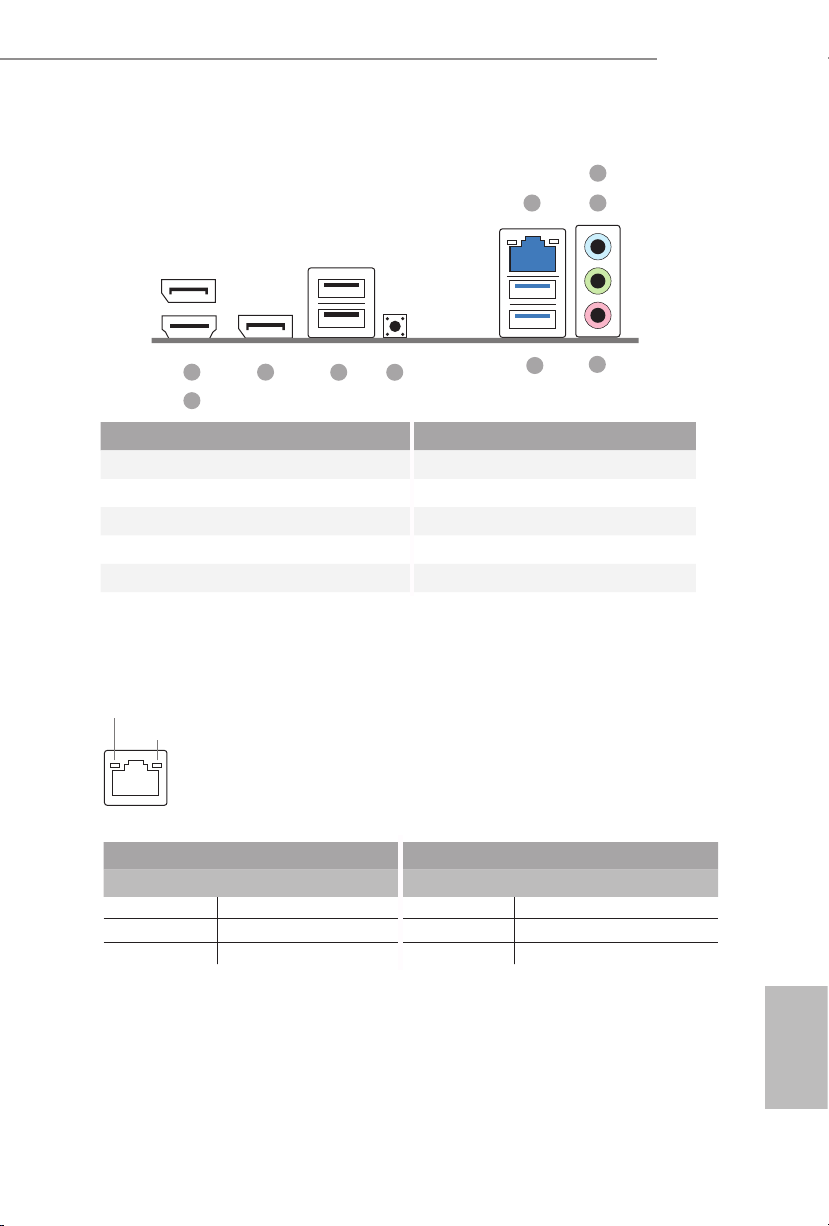
• ree graphics output options: 1x HDMI, 2 x DisplayPort 1.4
• Supports Triple Monitor
• 1 x HDMI 2.1 TMDS/FRL 8G Compatible, supports HDR,
HDCP 2.3 and max. resolution up to 4K 120Hz
• 2 x DisplayPort 1.4 with DSC (compressed), support HDCP
2.3 and max. resolution up to 4K 120Hz

8 9
English
Audio • Realtek ALC897 Audio Codec
LAN • 2.5 Gigabit LAN 10/100/1000/2500 Mb/s
• Dragon RTL8125BG
• Supports Dragon 2.5G LAN Soware
- Smart Auto Adjust Bandwidth Control
- Visual User Friendly UI
- Visual Network Usage Statistics
- Optimized Default Setting for Game, Browser, and
Streaming Modes
- User Customized Priority Control
Front
Panel I/O
• 1 x Headphone/Headset Jack
• 2 x USB 3.2 Gen1 Type-A Ports
• 1 x USB 3.2 Gen1 Type-C Port
• 2 x USB 2.0 Ports
Rear Panel
I/O
• 1 x HDMI Port
• 2 x DisplayPort 1.4
• 2 x USB 3.2 Gen1 Ports
• 2 x USB 2.0 Ports
• 1 x RJ-45 LAN Port
• 1 x BIOS Flashback Button
• HD Audio Jacks: Line in / Front Speaker / Microphone
Storage CPU:
• 1 x Blazing M.2 Socket (M2_1, Key M), supports type 2280
PCIe Gen5x4 (128 Gb/s) mode*
• 1 x Hyper M.2 Socket (M2_2, Key M), supports type 2280
PCIe Gen4x4 (64 Gb/s) mode*
ASMedia ASM1061:
• 2 x SATA3 6.0 Gb/s Connectors
* Supports NVMe SSD as boot disks

8 9
English
X600-ITX
RAID • Supports RAID 0, RAID 1 and RAID 10 for M.2 NVMe stor-
age devices*
* Requires additional M.2 NVMe expansion cards to support
RAID 10
Connector • 1 x Chassis Intrusion Header
• 1 x CPU Fan Connector
* e CPU Fan Connector supports the CPU fan of maximum 1A
(12W) fan power.
• 1 x Chassis Fan Connector (4-pin)
* e Chassis Fan Connector supports the chassis fan of maxi-
mum 1A (12W) fan power.
• 1 x 24 pin ATX Power Connector
• 1 x 8 pin 12V Power Connector
• 1 x Front Panel Header
• 1 x USB 2.0 Header (Supports 2 USB 2.0 ports)
BIOS
Feature
• AMI UEFI Legal BIOS with GUI support
Hardware
Monitor
• CPU, Chassis Temperature Sensing
• CPU, Chassis Fan Tachometer
• CPU, Chassis Quiet Fan (Auto adjust chassis fan speed by
CPU temperature)
• CPU, Chassis Fan Multi-Speed Control
• CASE OPEN detection
• Voltage monitoring: +12V, +5V, +3.3V, CPU Vcore
OS • Microso® Windows® 10 64-bit
Certica-
tions
• FCC, CE
• ErP/EuP ready (ErP/EuP ready power supply is required)
Please realize that there is a certain risk involved with overclocking, including adjusting
the setting in the BIOS, applying Untied Overclocking Technology, or using third-party
overclocking tools. Overclocking may aect your system’s stability, or even cause damage to
the components and devices of your system. It should be done at your own risk and expense.
We are not responsible for possible damage caused by overclocking.

10 11
English
is is a Deep mini-ITX form factor motherboard. Before you install the
motherboard, study the conguration of your chassis to ensure that the
motherboard ts into it.
Pre-installation Precautions
Take note of the following precautions before you install motherboard components
or change any motherboard settings.
• Make sure to unplug the power cord before installing or removing the motherboard.
Failure to do so may cause physical injuries to you and damages to motherboard
components.
• In order to avoid damage from static electricity to the motherboard’s components,
NEVER place your motherboard directly on a carpet. Also remember to use a grounded
wrist strap or touch a safety grounded object before you handle the components.
• Hold components by the edges and do not touch the ICs.
• Whenever you uninstall any components, place them on a grounded anti-static pad or
in the bag that comes with the components.
• When placing screws to secure the motherboard to the chassis, please do not over-
tighten the screws! Doing so may damage the motherboard.
Chapter 2 Installation

10 11
English
X600-ITX
2.1 Installing the CPU
1. Before you insert the 1718-Pin CPU into the socket, please check if the PnP cap is on the
socket, if the CPU surface is unclean, or if there are any bent pins in the socket. Do not
force to insert the CPU into the socket if above situation is found. Otherwise, the CPU
will be seriously damaged.
2. Unplug all power cables before installing the CPU.
Tutorial Video
Turn your CPU to the correct orientation before opening
the CPU socket cover.

12 13
English
Carefully place the CPU in as at as
possible. Do not drop it.
4
12
A
B
3

12 13
English
X600-ITX
6
7
5
Please save the cover if the processor is removed. e cover must be placed if you wish to
return the motherboard for aer service.
Make sure the black cover plate
is always in place until it pops o
when closing the socket lever.
Make sure the CPU is aligned with the
socket before locking it into place.

14 15
English
2.2 Installing the CPU Fan and Heatsink
Aer you install the CPU into this motherboard, it is necessary to install a larger
heatsink and cooling fan to dissipate heat. You also need to spray thermal grease
between the CPU and the heatsink to improve heat dissipation. Make sure that the
CPU and the heatsink are securely fastened and in good contact with each other.
Installing the CPU Cooler
Please turn o the power or remove the power cord before changing a CPU or heatsink.
2
1

14 15
English
X600-ITX
4
3
CPU_FAN1

16 17
English
2.3 Installing Memory Modules (DIMM)
is motherboard provides four 288-pin DDR5 (Double Data Rate 5) DIMM slots,
and supports Dual Channel Memory Technology.
Recommended Memory Conguration
1 DIMM
2 DIMMs
4 DIMMs
e rst boot may take some time.
Please be patient and refer to the following table for booting time.
*It may vary by dierent setups.
A1 A2 B1 B2
V
A1 A2 B1 B2
VV
A1 A2 B1 B2
VVVV
1. For dual channel conguration, you always need to install identical (the same brand,
speed, size and chip-type) DDR5 DIMM pairs.
2. It is unable to activate Dual Channel Memory Technology with only one or three memory
module installed.
3. It is not allowed to install a DDR, DDR2 , DDR3 or DDR4 memory module into a DDR5
slot; otherwise, this motherboard and DIMM may be damaged.
4. e DIMM only ts in one correct orientation. It will cause permanent damage to the
motherboard and the DIMM if you force the DIMM into the slot at incorrect orientation.
Memory 1st boot after clear CMOS
2 x 16GB 90 sec
2 x 32GB 150 sec
4 x 16GB 170 sec
4 x 32GB 315 sec

16 17
English
X600-ITX
e DIMM only ts in one correct orientation. It will cause permanent damage to
the motherboard and the DIMM if you force the DIMM into the slot at incorrect
orientation.
1
2
3

18 19
English
2.4 Expansion Slot (PCIe Slot)
ere are 1 PCIe slot on the motherboard.
PCIe slot:
PCIE1 (PCIe 4.0 x16 slot) is used for PCIe x16 lane width graphics cards.
Before installing an expansion card, please make sure that the power supply is
switched o or the power cord is unplugged. Please read the documentation of the
expansion card and make necessary hardware settings for the card before you start
the installation.
Table of contents
Languages:
Other Mini-Itx Motherboard manuals