Mini Warbirds Spitfire User instructions

(O
•D
c
Assembly
and
OperatingManual
Specification:
*Length:
2i-3/io"(540mm)
*Wing
Span:
26-i/5"(665mm)
*FlyingWeight:
11-3/10
oz
(320g)
Spitfire

Assembly
and
OperatingManual
Spitfire
Dearcustomer,
Congratulations
on
your
choice
ofa
factory-assembled
model
aircraft
from
the
Mini
Warbirds
range
and
thank
you
for
placingyour
trust
inus.
The
model
can
very quickly
be
completedready
to
fly.
Pleasereadrightthroughtheseinstructions
and
the
separate
Information
sheetsbefore
attempting
to
assemble
andflythe
model,
as
this
will
make
it
much
easier
to
complete
the
tasks
required.
All
directions,such
as
"right-hand",
areas
seen
from
the
tail
ofthe
model,looking
forward.
Notes
onthe
powersystem
A
brushless
outrunner
motor,
propeller
and
spinner
are
factory-installed.
The
motor
is
connected
tothe
speedcontroller,
ready
to
use,
andthe
controller
is
correctly
setup
at
the
factory.
To
complete
the
powersystem
allyou
have
todo
is
connect
the
LiPo
flight
battery.
The
radiocontrolsystem
with
at
leastfourchannels.
We
particularly
recommend
2.4GHz
systems.
The
receivingsystem
is
powered
bythe
speed
controller'sintegral
BEC
system.
Before
you
check
the
model'sworking systems,
set
the
controlsurfaces
to
neutralfrom
the
transmitter (transmittersticks
and
trimscentral).
Before
operating
the
modelalwaysmove
the
throttlestick
tothe
"motor
stopped"
positionbefore
switching
the
transmitter
on.
Only
thenconnect
the
flight
battery.
To
switchoff,firstdisconnect
the
flightpackfrom
the
speedcontroller,
and
only
thenswitch
the
transmitter
off.
Glued
joints,suitableadhesives
Foam
safeepoxy
is
recommended
and
available
frommostreputablemodel
retail
shops.
Trial-fit
all
parts
"dry"beforeapplying
glue.
Follow
the
recommendedcuringtimesuggested
by
the
glue
manufacturen
Allow
the
glue
to
fully
cure(harden)
tothe
pointwhere
the
joint
canbe
placedunderstress.
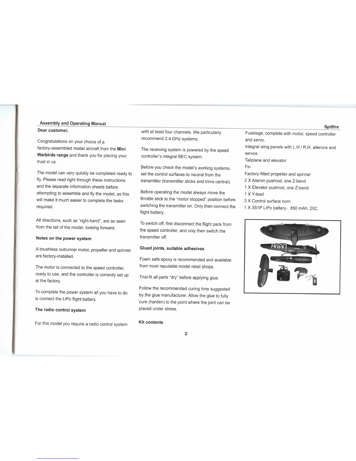
Fuselage,completewithmotor,speedcontroller
and
servo.
Integral
wing
panels
with
L.H/
R.H.
ailerons
and
servos
Tailplane
and
elevator
Fin
Factory-fitted
propeller
and
spinner
2X
Aileron
pushrod,
one
Z-bend
1X
Elevator
pushrod,
one
Z-bend.
1X
Y-lead
3
X
Control
surface
horn
1
X3S1P
LiPo
battery,
850
mAh,
20C
For
thismodel
you
require
a
radiocontrolsystem
Kit
contents

Assembly
and
Operating
Manual
Spitfire
Fig.
1
-
Apply
glue
to the
slot
of
mainwing
and
control
surfacehorn.(glue
not
included)
Fig.
2
-
Connect
the
aileronpushrod
tothe
aileron
servo
arm,
and
thenconnect
ittothe
controlsurface
horn.
Fig.
3
-
Connect
the
aileronpushrod
tothe
controlsurface
horn
at
firsthole.
Fig.
4
-
Reverse
the
procedure
tothe
left
wing.
The
photo
shows
the
finishedview.

Assembly
and
OperatingManual
Spitfire
.
i
Fig.
5
-
Apply
glue
tothe
mainwing.
Fig.
6
-
Apply
glue
tothe
fuselage.
Fig.
7
-
Assemble
the
mainwing
tothe
fuselage.
Fig.
8
-The
photoshows
the
finished
view.

Assembly
and
OperatingManual
Spitfire
Fig.9
-
Apply glue
tothe
slot
of
horizontalstabilizer.
Fig.
10
-
Glue
the
control
surface
horn
tothe
horizontal
stabilizer
and
hold
in
position
until
the
gluesets.
Fig.
11
-
Assemble
the
elevatorpushrod
tothe
first
hole.
Fig.
12
-
Makesure
the
pushrod
is
firmly
fixed
tothe
control
surface
horn,
and
then
apply
glue
tothe
horizontal
stabilizer.

Assembly
and
OperatingManual
Spitfire
s
©
Fig.
13
-
Applyglue
tothe
horizontalstabilizer.
Fig.
14
-
Glue
the
horizontal
stabilizer
tothe
fuselage,
and
make
sure
the
elevatorpushrod connect
tothe
fuselage
servo
at
firsthole.
Fig.
15
-
Hold
in
position
until
the
gluesets.
The
photo
shows
the
finished
view
Fig.
16
-
Appleglue
tothe
vertical
fin.
6

Assembly
and
Operating
Manual
Spitfire
Fig.
17
-
Glue
vertical
fintothe
fuselage.
Fig.
18
-
Photoshows vertical
fin
assemble
tothe
fuselage.
Fig.
19
-
Photo
shows
the
aileron
servos
connects
tothe
Y-lead.
Fig.
20
-
Photoshows
the
speedcontroller connects
tothe
motor

Assembly
and
Operating
Manual
Spitfire
Fig.
21
-
Connect
tothe
receiver
and
place
the
receiver
in
the
middle
ofthe
fuselage.
Fig.
22
-
Photoshows
all
parts
are
well
assembled.
Fig.
23
-
Photoshowsbatteryleadsconnected
tothe
speed
controller.
Fig.
24
-
Opening
and
closing
the
canopy:
The
canopy
is
retained
bythe
cowl
atthe
front,
andbya
tongue
atthe
rear
-To
open
the
canopy,
slide
it
forward,
raise
itat
the
rear
and
lift
itoff
-
Reverse
the
procedure
to
replace
the
canopy.

Assembly
and
Operating
Manual
Spitfire
Fig.
25
-
Place
the
propellersets.
Fig.
26
-
Assemble
the
propellerbase
Fig.
27
-
Assemble
the
propeller.
Fig.
28
-
Assemble
the
spacer.

Assembly
and
Operating
Manual
Spitfire
Fig.
29
-
Assemble
the
screwnut.
Fig.
30
-
Fixthe
spinnerwithscrews.
Fig.
31
-
Photoshows
the
fixedview.
Fig.
32
-
Congratulations,
you
havecompleted
the
assemblyprocess.
We
hope
you
enjoyflyingyour
new
model!
10

Assembly
and
Operatin
g
Manual
Spitfire
Fig.
33
-
Charge
the
flight
battery;
connect
the
Equalizer
leadusing
and
adapterleadmatchingyour
charger
(adapterlead
not
included).
Fig.
34
-
Switch
the
transmitter
on,and
move
the
throttle
stick
tothe
"MotorOFF"position.(DiagramMODE
1
right
throttle
controlstick)
11

Assembly
and
OperatingManual
Spitfire
Aileron
right
Elevator
Figs.
35and36
-
Check
the
channelassignment
ofthe
control
surfaces,
and
swapover
the
connectors
atthe
receiver
if
necessary.
-
Check
the
neutralposition
ofthe
controlsurfaces.
Make
adjustments
tothe
clevises
if
necessary.
-
Stand
behind
the
model.
-
Check
the
direction
of
rotation
ofthe
servos.
-
When
you
move
the
aileronstick
tothe
right(a),
the
right-handaileron
(a)
shouldrise,
the
left-hand
aileron
(b)
fall.
-
Pull
the
elevatorstickbacktowards
you
(c),
and
the
rearedge
of
bothelevatorsshouldrise(c).
-If
eithercontrol
surface
function
works
the
wrong
way
round,correct
it
usingyourtransmitter's
servo
reversefacility
for
thatfunction.
-
Checkthat
allthe
linkages
are
firmlyfixed,
but
free-moving.
-
We
recommend
that
youset
around
50%
Expo
on
the
aileron
and
elevatorfunctions.
Fig.
37
Balancing
-
Place
the
canopy
onthe
fuselage.
-
Place
the
battery
inthe
model
of
balancing;
donot
connect
it.
12

Assembly
and
Operating
Manual
Spitfire
Motor
Motor"ON"
-
Make
the
Centre
of
Gravity
on
both
sides.
-
Support
the
model
atthe
marked
C.G.
and
allow
it
to
hangfreely.
The
model
is
correctlybalanced
when
it
hangs
level,
ideally with
the
noseinclined
slightly
down.
-
Adjust
the
position
ofthe
flight
battery
if
necessary.
-
Mark
the
battrylocation
inthe
fuselage,
so
that
you
canbe
confident
of
replacing
itinthe
same
position
after
removing
it.
Fig.
38
checking
the
electricpowersystem
-
Caution:
position
the
throttle
stick
in
such
a way
that
the
motorcannotpossiblystartrunning.
-
Switch
the
transmitter
on,and
connect
the
flight
pack
-
Check
the
direction
of
rotation
ofthe
motor:when
viewed
from
the
front,
the
output
shaft
mustrotate
anti-clockwise.
If
this
isnotthe
case,perhaps
because
youare
using
components
other
than
thoserecommended,swapover
anytwo
motor
wires
to
reverse
the
direction
of
rotation.
13

Assembly
and
OperatingManual
Spitfire
Note:whenever
youare
installing,
adjusting
or
servicing
the
powersystem,
keep
well
clear
ofthe
rotational
plane
ofthe
propeller
-
injury
hazard.Ensure
also
that
nobodystands
in
front
ofthe
modelwhen
the
motor
is
running.
-
Firstdisconnect
the
battery
from
the
speed
controller,
and
thenswitch
the
transmitter
off.
-The
model
is
ready
for
flying
once
you
have
recharged
the
battery.
Test-flying,
flyingnotes
Read
the
sections
inthe
Safety
Notes
entitled"Routine
pre-flight
checks"
and
"Flying
the
model"
beforeattempting
to
fly
the
model
forthe
firsttime.
-
Advice
on
control
surface
travels.
-
The
statedcontrolsurfacetravels
are
just
a
guide
forthe
first
few
flights.
Every
pilot
will
need
to
adjust
the
settingsslightly
to
suit
his
orher
individual
flying
style.
Exponential
settings
should
also
besetto
suit
your
personal
preference.
-
For
your
first
few
flights
pleasewait
fora day
with
no
more
than
a
gentle
breeze.
-
A
goodflying
site
consists
ofa
large,
flat,open
grassy
field,
devoid
of
trees,fences,
high-tensionoverheadcablesetc.
-
Repeat
the
check
ofallthe
workingsystems.
-
Askan
experienced
modeling
friend
to
hand-launch
the
aircraft
for
you.
He
should
be
capable
of
giving
the
model
a
reasonablystrong,
flat
launch.
-
The
modelmust
be
launcheddirectlyinto
any
wind.
-
With
the
motorrunning
at
full-throttle,
give
the
aeroplane
a
firmlaunchdirectlyinto
any
breeze,
with
the
fuselage
and
wings
level.
-
Allow
the
Spitfire
tofly
straight aheadinitially;
don't
initiate
turns
close
tothe
ground.
-
Adjust
the
controlsurface
trims
if
necessary,
so
that
the
model
flies
straight with
a
reasonable
rate
of
climb
"hands
off'.
-
Check
the
model'sreaction
to
controlinputs.
If
necessary,
youmay
need
to
increase
or
reduce
the
control
surface
travels
after
the
first
landing.
-
Check
the
aeroplane's stallingspeed
ata
safe
height.
Keep
the
model'sspeedwell above
the
stall
for
the
landing
approach.
If
you
needed
to
adjust
the
trimsduring
the
test-flight,
correct
the
length
ofthe
appropriate
pushrodonce
the
model
is
back
onthe
ground,
thenreturn
the
transmittertrims
to
centre
so
that
full
trimtravel
is
available
to
bothsides
of
neutral
for
subsequent
flights.
We
reserve
the
right
to
introducétechnical
modifications
and
suggestthat
you
check
our
website
for
updates.
14