Miramar P5 PTP User manual

1
INSTALLATION GUIDE —P5 PTP / CL5 CLIENT
PACKAGE CONTENTS
V 1.0
This document describes the installation steps for the above products. For user interface guidelines, Please refer to a separate configuration guide for
each product. Some tutorial information is available in this configuration guide. For more details, please refer to white papers or tutorials available on
our website, www.miramarnetworks.com.
NOTE: The type of POE power supply (included in the package) will vary, depending on the country of deployment.
Packing List:
• Radio unit with the bottom cover
• POE power supply
• Mounting bracket
• Security screw
• Rubber Brake
• 2 x hose clamps (pole mounting)
• 4 x wall plus + screws (wall mounting)
Radio + Antenna unit Mounting Bracket

2
CONNECTING ETHERNET CABLE
Grab cover locks with two fingers. Hold them in-
ward and take out the cover.
Connect your Ethernet cable. Make sure that the CAT5e/6
cable is outdoor rated (shielded, UV-protected).
There are two Ethernet connectors. For the primary
Ethernet connection, use the port on the left side, as
shown in the picture (LEFT). If you want to have a secon-
dary Ethernet port need, use the port at the center.
Slide the cable through the hole opening.
Close the cover. Make sure that the cover locks
are locked in securely.
Cover lock
Hole opening
Use Ethernet port to the left (Not at the center)

3
PREPARING MOUNTING BRACKET
Install the bracket on a pole using the supplied
hose clamps.
Tighten the hose clamp screw so that the bracket
is securely fastened.
Insert the Rubber Brake, as shown in the picture
(LEFT).
Attach the radio to the bracket and slightly tighten the
mounting nut.
You should be able to move the radio unit at this time.
Mounting Nut
Rubber Brake

4
ALIGNING THE ANTENNA
You have now 3 degrees of freedom (elevation,
azimuth and rotation) to move the antenna to the
desired position.
Make sure that antenna rotation position is opti-
mized (in addition to elevation and azimuth) so
that the polarization between the two antennas is
aligned correctly.
Once the antenna is aligned, tighten the mounting
nut securely. Make sure that the antenna is not
moved during the tightening process.
Once the antenna is aligned, tighten the mounting
nut securely. Make sure that the antenna is not
moved during the tightening process.
To secure the desired position, use the security
screw which cuts into the ball part of the bracket.
NOTE: For details on how to align the antenna, refer to the next pages first. Set up the alignment procedures before you en-
gage in the steps described on this page.

5
ANTENNA ALIGNMENT PROCEDURE
NOTE: Antenna alignment process requires you to log into the user interface. Refer to the CONFIGURATION GUIDE for details
on logging into the user interface.
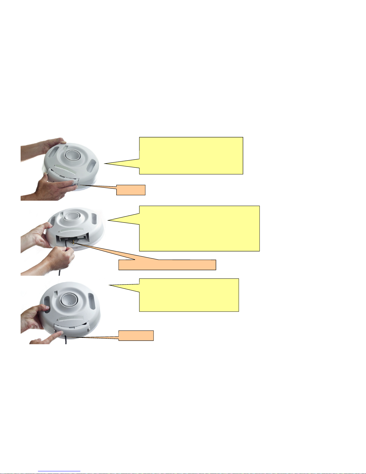
The radio produces an audible tone allowing antenna alignment without the need for additional monitoring hardware.
CAUTION -A ping, or other network traffic is needed to ensure reliable operation of the alignment feature, in which case the Activity indicated will
be in a green state. If no network traffic is detected, the Activity indicator will be in a red state.
The pulsed tone will begin once an RF link has been established, regardless of quality. It is useful to reduce the RF modulation setting to its
lowest value (BPSK) during the antenna alignment procedure to maximize the system’s link capture envelope/angle.
The audible repetition rate will increase as RSSI improves; a higher value will cause a faster rate. To assist with both coarse and fine tuning, the
rate is NOT a simple function of RSSI value. Rather, the rate will continue to increase as long as adjustments deliver an improved RSSI. As
soon as any degradation (alignment ‘overshoot’) is detected, the rate quickly falls, regardless of the amount of reduction. Thus, the system is
useful for both coarse and fine tuning of the antenna position.
To ensure the system will deliver adequate link reliability, it is recommended that the operator verify the numerical RSSI following antenna
alignment.
The audible function is enabled for the first 30 minutes after
Regardless of whether the audible function is enabled or disabled, the unit will emit a short audible tone upon initial power-up.
The following page will describe the user interface setup.

6
USER INTERFACE SCREEN FOR ANTENNA ALIGNMENT
Audio Alignment Mode: This mode should be used
when you are aligning the antenna. Once you click
RUN button, the antenna alignment mode will operate
for 30 minutes.
This mode will turn off upon reboot unless you have
the Run on Reboot mode on.
Run on Reboot: this can be used for automatic
running of antenna alignment mode upon reboot for
the duration (in minutes).
Make sure that this mode is turned off for normal
operation of the link.
For best results, continue to run ping traffic between your PCs during the antenna alignment process. Continuous traffic is neces-
sary for the radio to generate reliable RSSI data.
Use the buzzer sounds for antenna alignment. Buzzer sounds become more frequent as the antenna alignment improves. Try to
peak the antenna alignment by putting
Launch: this starts the spectrum analyzer mode.
The main purpose of this mode is to aid you in as-
sessing which channels are the most clear before
selecting the channel of operation.

7
SPECTRUM ANALYZER
It is beneficial for the installer to run a spectrum analysis during a site survey, especially in an RF-congested area or if the user is
planning on multiple links at the site.
This manual suits for next models
1
Table of contents