957134_GF_AC
ASSEMBLY AND INSTALLATION
INSTRUCTIONS
(5150 - 5875 MHz)
APPLICATION
Designed for wireless LAN service, the S51514WP
is a directional patch array enclosed in a uv-stable weatherproof
radome. The focused radiation pattern may be used to extend
point-to-point link coverage or to provide targeted sector coverage
in the 5 Ghz band.
SAFETY
The
S51514WP
and all associated equipment
should be installed in accordance with applicable local and
national electrical code guidelines to ensure safe operation.
ANTENNA LOCATION
The S51514WP may be mounted at interior or exterior
locations. A line-of-sight signal path works best for point-to-point
links. Although 5 Ghz signals penetrate cubical dividers and
interior partitions with little attenuation, reinforced block walls,
banks of metal cabinets, or steel shelving may attenuate signals
or cause multipath, a condition where reflected signals interfere
with the primary signal. Because antenna beamwidth is narrow,
it is important to aim the antenna .n
iaccurately during installatio
in order to provide optimum gain and best performance.
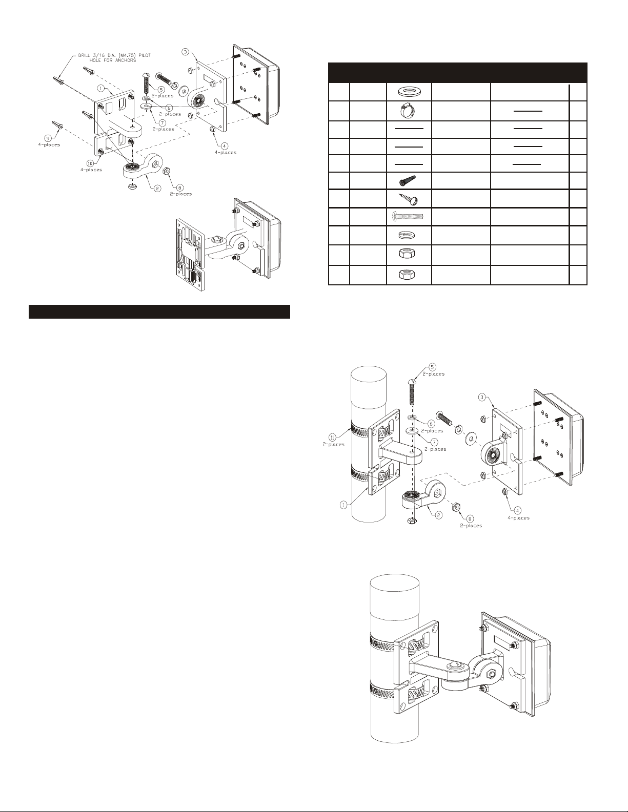
MOUNTING
The S51514WP is supplied with a
universal articulating
mount that accepts mast diameters up to 2 inches (5.1cm) or
mounts to any flat vertical surface. This mount is especially
designed to provide wide-range articulation in both the azimuth
and elevation planes.
SPECIFICATIONS
Model: S51514WP
Frequency: MHz 5150-5875
Gain: 13 dBi Nominal
VSWR: 2:1
E-Plane (3 dB beamwidth): 27
H-Plane (3 dB beamwidth): 31
Polarization: Linear, Vertical
Front to Back Ratio: 20 dB
Weight lb. (kg): .65 (.3)
Mounting: Wall / Mast
Dimensions in.(cm): 4 x 4 x 1.5
(10.2 x 10.2 x 3.8 )
Enclosure: PVC / Acrylic
Mast Diameter Max. in.(cm): 2 (5.1) For Supplied Strap
Power (Watts): 10
GROUNDING
System grounding and lightning protection are Essential
especially for exterior-mounted antennas exposed to the
elements. Never install an antenna where it may fall and contact
electrical lines (refer to the National Electrical Code).
S51514WP
o
o
48 PERIMETER ROAD, MANCHESTER, NH 03103
Tel: 603-627-7877-Fax: 603-627-1764
W A R R A N T Y
A N D
L I A B I L I T Y
C u s hc r a ft
C o rp o r ati on
shall
not
be
lia b le
for
any
incid e n tal
or
consequential
damages
which
may
result
from
a
defect,
or
use,
improper
or
otherwise
or
installation,
improper
or
otherwise.
Please
contact
your
vendor
for
technical
support
and
warranty
service
.
LIMITED
WARRANTY
CUSHCRAFT CORPORATION, P.O. BOX 4680, MANCHESTER, NEW HAMPSHIRE
03108, WARRANTS TO THE ORIGINAL CONSUMER PURCHASER FOR TWO YEARS
FROM DATE OF PURCHASE THAT EACH CUSHCRAFT ANTENNA IS FREE OF
DEFECTS IN MATERIAL OR WORKMANSHIP. IF, IN THE JUDGMENT OF CUSHCRAFT,
ANY SUCH ANTENNA IS DEFECTIVE, THEN CUSHCRAFT CORPORATION WILL, AT
ITS OPTION, REPAIR OR REPLACE THE ANTENNA AT ITS EXPENSE WITHIN THIRTY
DAYS OF THE DATE THE ANTENNA IS RETURNED (AT PURCHASER'S EXPENSE) TO
CUSHCRAFT OR ONE OF ITS AUTHORIZED REPRESENTATIVES. THIS WARRANTY IS
IN LIEU OF ALL OTHER EXPRESSED WARRANTIES, ANY IMPLIED WARRANTY IS
LIMITED IN DURATION TO ONE YEAR. CUSHCRAFT CORPORATION SHALL NOT BE
LIABLE FOR ANY INCIDENTAL OR CONSEQUENTIAL DAMAGES WHICH MAY RESULT
FROM A DEFECT. SOME STATES DO NOT ALLOW LIMITATIONS ON HOW LONG AN
IMPLIED WARRANTY LASTS OR EXCLUSIONS OR LIMITATIONS OF INCIDENTAL OR
CONSEQUENTIAL DAMAGES, SO THE ABOVE LIMITATION AND EXCLUSION MAY NOT\
APPLY TO YOU. THIS WARRANTY GIVES YOU SPECIFIC LEGAL RIGHTS, AND YOU
MAY ALSO HAVE OTHER RIGHTS WHICH VARY FROM STATE TO STATE. THIS
WARRANTY DOES NOT EXTEND TO ANY PRODUCTS WHICH HAVE BEEN SUBJECT
TO MISUSE, NEGLECT, ACCIDENT OR IMPROPER INSTALLATION, ANY REPAIRS OR
ALTERATIONS OUTSIDE OF THE CUSHCRAFT CORPORATION FACTORY WILL NULLIFY
THIS WARRANTY.
SPECIFICATIONS SUBJECT
TO CHANGE WITHOUT
NOTICE