manuals.online logo
Brands
  1. Home
  2. •
  3. Brands
  4. •
  5. Mircom
  6. •
  7. Motherboard
  8. •
  9. Mircom MGC MIX-4090 User manual

Mircom MGC MIX-4090 User manual

LT‐6146rev1.17/16/19
25 Interchange way, Vaughan Ontario. L4K 5W3
Phone: 905.660.4655; Fax: 905.660.4113
INSTALLATION AND MAINTENANCE INSTRUCTIONS Web: www.mircom.com
MIX-4090 DEVICE PROGRAMMER
ABOUT THIS MANUAL
This manual is included as a quick reference for use of the device to
set addresses on sensors and modules in the MIX-4000 series.
Note: This manual should be left with the owner/operator of this
equipment
Description:
The MIX-4090 programmer is used to set or read addresses of MIX-
4000 devices. It can also read devices’ parameters such as device
type, firmware version, condition and thermal settings. The
programmer is small and lightweight and has a built-in base for heat
and smoke detectors, see figure 2. A plug-in cable is supplied to
program permanently wired devices, see figure 4. Basic functions are
quickly accessible through four keys: Read, Write, Up and Down. A 2
x 8 characters LCD will display all required information without need
for an external screen or PC, see figure 1.
FIGURE 1 PROGRAMMER FRONT:
The unit uses an inexpensive 9V PP3 size (6LR61, 1604A) alkaline
battery and will automatically shut down when the unit is unused for
more than 30 seconds. Start-up time is only 5 seconds. Remaining
battery capacity will be displayed each time the device is used. The
battery is easily accessible through a sliding cover at the bottom of
the unit, shown in figure 2.
FIGURE 2 PROGRAMMER BACK:
Address programming (Devices with bases):
Warning: Do not disconnect a device during address storing
operation. This may damage the device.
Install the device in the programmer’s base with the bar on the
device about 3/8” (7mm) to the right of the bar on the base: The
device should drop in the base without effort. Push on the device and
turn it clockwise until the two bars are aligned, see figure 3.
FIGURE 3 ALIGN BARS:
UP
DOWN
WRITE
READ
9V Battery cover
LT‐6146rev1.17/16/19
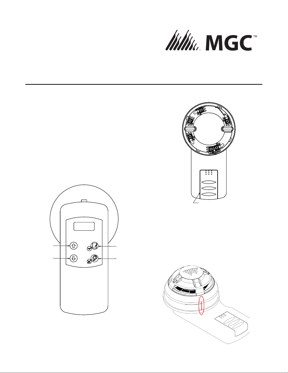
Press on any key to start the process (see figure 1 for key locations).
The programmer will start up and will display the last address that
was read or written. To read the current device address, press on the
Read key (showing a magnifier and red X). If the address has to be
modified, use the up and down keys at the left. To program the
displayed address in the device, press on the Write key (showing a
pen & paper symbol and a green check mark).
Once the address is programmed in the device, remove it from the
programmer by twisting it counter clockwise. Most projects require
that a device address must be visible for inspection: MIX-4000 bases
have a breakable tab that can be inserted on the outside of the base
to show the address. See MIX-40XX installation sheet for details.
Address programming (Permanently installed devices):
Warning: Do not disconnect a device during address storing
operation. This may damage the device.
Plug the programming cable in the MIX-4090 using the connector on
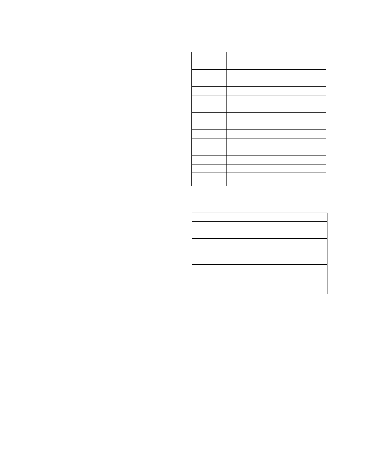
top, shown in figure 4. Locate the programming connector on the
device, see figure 5. If the device is already installed, it may be
necessary to remove the wall plate covering the device to access the
connector.
FIGURE 4 PROGRAMMER CABLE ATTACHMENT
Unless the device has to be replaced, there is no need to disconnect
wires from it. However the whole SLC line should be disconnected
from the loop driver when devices are programmed while in place. If
the SLC line is powered, the programmer may be unable to read or
write the device data.
Connect the cable to the device (see figure 5): Please note that the
programming plug is polarized to ensure that it is inserted in the cor-
rect position. Then proceed as above to read and set addresses.
When done, use a pen or labels to indicate the device address as
required by the project.
FIGURE 5 CABLE ATTACHMENT TO DEVICE
Reading device parameters:
Several device parameters can be read though the MIX-4090
programmer. First the device must be connected to the programmer
as described for address setting. After the programmer is turned on
and is showing the address screen, press on the “Read” key for
about five seconds. The message “Family ↨Analog” should appear.
If “Family ↨Conv” is shown, use the up-down keys to get to “Family
↨Analog” . When done, press on the “Write” key to enter the sub-
menus.
The following parameters can then be accessed using the up and
down keys:
· Device type: “DevType” followed by device type. See table
1 for a full list of devices.
· Series: Mircom should be displayed.
· Customer: This parameter is not used.
· Battery: remaining battery capacity
· Test Date: “TstDate” followed by date of device testing in
production
· Production Date: “PrdDate” followed by date of device
fabrication
LT‐6146rev1.17/16/19
· Dirty: Significant for Photo detectors only. Brand new
detectors should be around 000%. A value near 100%
means that device must be cleaned or replaced.
· Standard value: “StdValue” followed by a number.
Significant for detectors only, normal value is around 32.
Value 0 or a value over 192 (alarm threshold) may indicate
a defective or dirty device.
· Firmware version: “FrmVer” followed by number.
· Operation mode: “Op Mode” followed by Enter. Pressing
on the “Read” key will display a number showing the
operational mode of the device. This parameter should
only be accessed when requested by a Mircom Tech
Support operator. Modifying this parameter may make the
device unusable.
·
Programmer messages:
The programmer can display the following messages during
operation:
· “Fatal Error”: Device or programmer has failed and may
need replacement.
· “Storing”: A parameter is written into the device.
· Do not disconnect a device during this operation!
· “Address Stored”: Address has been successfully stored
on device.
· “Failed”: Current operation (first line of display) has failed.
· “Miss Dev”: The device has not responded to current
operation. Check connections or replace device.
· “No Addr”: No address is programmed. This may happen
for brand new devices address is read without prior
address write.
· “Low Batt”: Battery should be replaced.
Table 1: Device type returned by MIX-4090 programmer.
Table 2: Compatible devices
Display Device
Photo Photo Electric smoke detector
Thermal Heat detector
PhtTherm Photo Electric smoke and heat detector
I Module Input module
O Module Relay output module
OModSup Supervised output module
Conv Zon Conventional zone module
Multiple Multiple I/O device
CallPnt Call point
Sounder Wall or ceiling audible NAC
Beacon Strobe
Sound B Combined audible NAC and strobe
Remote L Remote visible indicator
Special This message can be returned for newer
devices not yet in the programmer’s list
Device Model number
Photoelectric smoke detector MIX-4010(-ISO)
Photo smoke/Heat Multi-sensor MIX-4020(-ISO)
Heat detector MIX-4030(-ISO)
Multi-use output module MIX-4046
Dual input module MIX-4040
Dual input mini-module MIX-4041
Conventional zone module and 4-20mA
interface
MIX-4042
Dual relay module MIX-4045

Popular Motherboard manuals by other brands

Texas Instruments RF430F5978 EVM Kit user guide

Texas Instruments

Texas Instruments RF430F5978 EVM Kit user guide

Fujitsu D2917 user guide

Fujitsu

Fujitsu D2917 user guide

Skyworks SiOCXO1-EVB user guide

Skyworks

Skyworks SiOCXO1-EVB user guide

Asus 90MB0VJ0-M0EAY0 manual

Asus

Asus 90MB0VJ0-M0EAY0 manual

Analog Devices EV-ADF5904SD2Z user guide

Analog Devices

Analog Devices EV-ADF5904SD2Z user guide

Avalue Technology EMX-CDD Quick installation guide

Avalue Technology

Avalue Technology EMX-CDD Quick installation guide

ST STEVAL-IDB011V1 quick start guide

ST

ST STEVAL-IDB011V1 quick start guide

Intel D915PDT Product guide

Intel

Intel D915PDT Product guide

Fujitsu MB39C026 manual

Fujitsu

Fujitsu MB39C026 manual

AvaLAN AW2400mR-EVAL user manual

AvaLAN

AvaLAN AW2400mR-EVAL user manual

Asus P3C2000 user manual

Asus

Asus P3C2000 user manual

TAIYO YUDEN WBSBMVGXB-1 manual

TAIYO YUDEN

TAIYO YUDEN WBSBMVGXB-1 manual

MSI H410M PRO-C user guide

MSI

MSI H410M PRO-C user guide

Norco BPC-7936 user manual

Norco

Norco BPC-7936 user manual

ASROCK A75 Extreme6 user manual

ASROCK

ASROCK A75 Extreme6 user manual

Renesas ISL6263AEVAL1Z user manual

Renesas

Renesas ISL6263AEVAL1Z user manual

EPOX EP-BX5C manual

EPOX

EPOX EP-BX5C manual

STMicroelectronics L62 Series user manual

STMicroelectronics

STMicroelectronics L62 Series user manual

manuals.online logo
manuals.online logoBrands
  • About & Mission
  • Contact us
  • Privacy Policy
  • Terms and Conditions

Copyright 2025 Manuals.Online. All Rights Reserved.