Miromico FMLR User manual

FMLR Development Board
RSS3
Versatile LoRaWAN® Development Board
Quickstart uide RSS3
Version 1.2
Miromico A - allusstrasse 4 - CH-8006 Zurich – Switzerland
Revision 1.21
1/17

About this Document
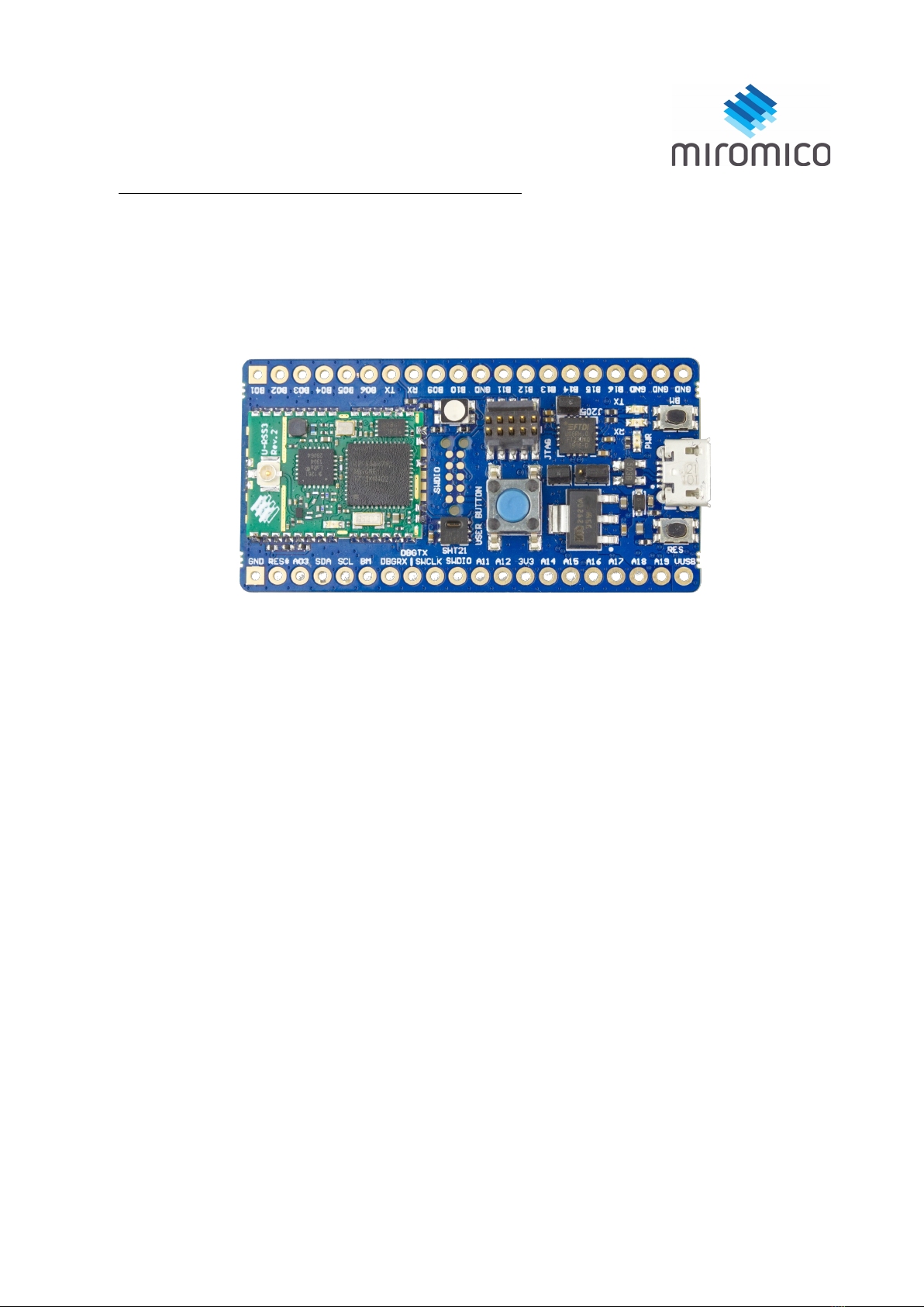
Title FMLR Development Board RSS3
Subtitle Versatile LoRaWAN® Development Board
Document Type Quickstart uide
Revision 1.21
Date 07.08.20
Document Status Preliminary
Contents
1 Overview.................................................................................................................................................. 3
1.1 Connectors and UI................................................................................................................................ 3
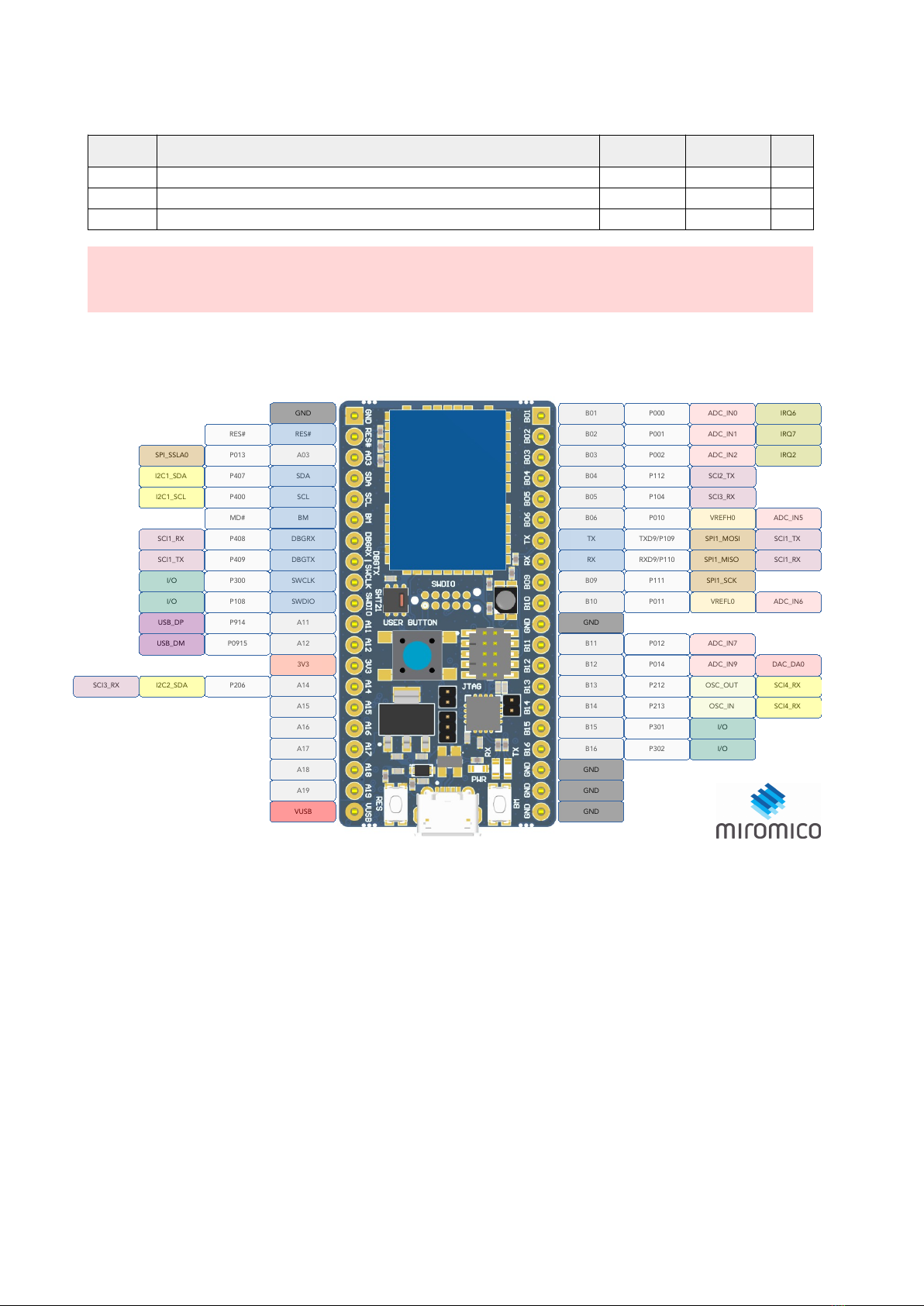
1.2 Pin-out................................................................................................................................................... 4
2 First steps................................................................................................................................................. 5
2.1 Powering on the Device........................................................................................................................5
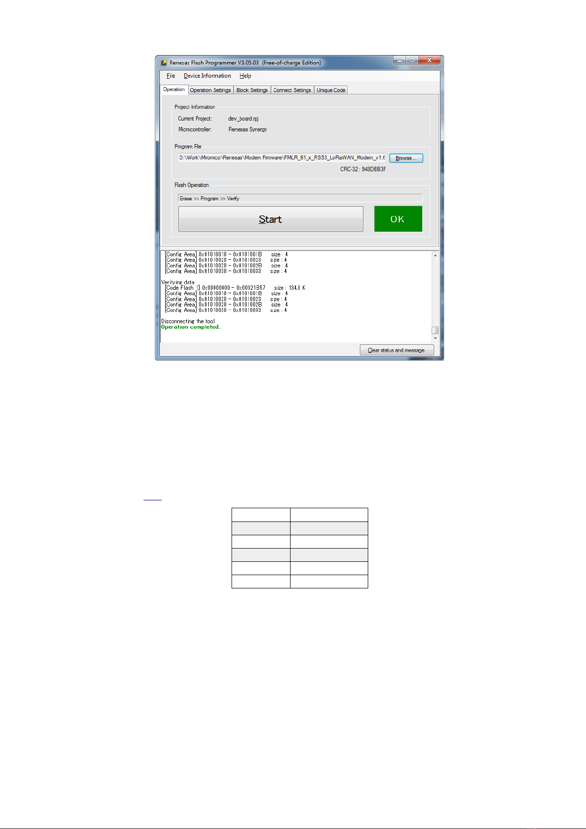
2.2 Programming the Device......................................................................................................................5
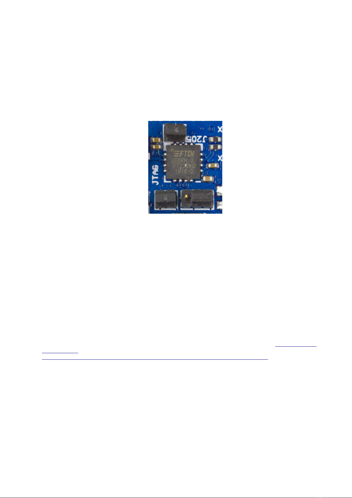
2.3 Access Seria Port of the Device by USB (UART)...................................................................................7
3 Application Development and Debugging..............................................................................................8
3.1 Prerequisites.......................................................................................................................................... 8
3.2 Connecting the Deve opment Board using SWD Programmer............................................................8
3.3 Getting the Sources.............................................................................................................................. 8
3.4 Copying the .pack Fi es......................................................................................................................... 9
3.5 Opening the project.............................................................................................................................. 9
3.6 Setting LoRaWAN Configuration........................................................................................................10
3.7 Setting the Synergy Configuration......................................................................................................11
3.8 Down oad and Debugging.................................................................................................................. 11
3.9 Connection to a LoRaWAN Network Server.......................................................................................13
4 Additional Information........................................................................................................................... 18
We reserve the right to make technical changes, which serve to improve the product, without prior notification.
SAFETY-CRITICAL, MILITARY, AND AUTOMOTIVE APPLICATIONS DISCLAIMER: Miromico products are not designed for and
will not be used in connection with any applications where the failure of such products would reasonably be expected to result in
significant personal injury or death (“Safety-Critical Applications”) without an Miromico officer's specific written consent. Safety-
Critical Applications include, without limitation, life support devices and systems, equipment or systems for the operation of
nuclear facilities and weapons systems. Miromico products are not designed nor intended for use in military or aerospace
applications or environments. Miromico products are not designed nor intended for use in automotive applications unless
specifically designated by Miromico as automotive-grade.
Miromico A - allusstrasse 4 - CH-8006 Zurich – Switzerland
Revision 1.21
2/17

1 Overview
1.1 Connectors and UI
Function Description
FMLR Module FMLR Module
LED User R B LED for debugging or user purpose
TA Connect Programming Interface for Tag Connect and Miromico programming adapter
Sensor SHT21 I2C environmental sensor
JTA Connector Programming Interface for JTA programmer
User Button For debugging or user purpose connected to PA0 of the MCU
Boot Mode Button Sets the Boot Mode of the FMLR Module
Micro-USB Port DC Input and debugging interface
Reset Button Resets and restarts the FMLR Module
LEDs Power and UART RX / TX LED
Jumper Positions Positions to place jumpers for potentially needed connections on the board
For more information on the FMLR Module please refer the the respective data sheets found on the
Miromico website:
•eneral information about modules and products: https://miromico.ch/iot/
•FMLR-61-X-RSS3 product page: https://miromico.ch/portfolio/fmlr_renesas/
•FMLR-61-X-RSS3 source repository: https://gitlab.com/fmlr/fmlr-61-x-rss3
Miromico A - allusstrasse 4 - CH-8006 Zurich – Switzerland
Revision 1.21
3/17

1.2 Pin-out
Pin Details in ax Unit
All Min / Max Voltage on All Pins -0.3 3.6 V
3V3 Input / Output Voltage Pin -0.3 3.6 V
VBUS Input / Output Voltage Pin -0.3 5.5 V
Warning:
Do not exceed the above mentioned maximum voltage values!
Miromico A - allusstrasse 4 - CH-8006 Zurich – Switzerland
Revision 1.21
4/17
Alternate Function Function MCU Pad Pin FMLR-xx-Rsx-xx Development Board – Pinout Pin MCU Pad Function Alternate Function
GND B01 P000 ADC_IN0 IRQ6
RES RES B02 P001 ADC_IN1 IRQ7
SPI_SSLA0 P013 A03 B03 P002 ADC_IN2 IRQ2
I2C1_SDA P407 SDA B04 P112 SCI2_TX
I2C1_SCL P400 SCL B05 P104 SCI3_RX
MD BM B06 P010 VREFH0 ADC_IN5
SCI1_RX P408 DBGRX TX TXD9/P109 SPI1_MOSI SCI1_TX
SCI1_TX P409 DBGTX RX RXD9/P110 SPI1_MISO SCI1_RX
I/O P300 SWCLK B09 P111 SPI1_SCK
I/O P108 SWDIO B10 P011 VREFL0 ADC_IN6
USB_DP P914 A11 GND
USB_DM P0915 A12 B11 P012 ADC_IN7
3V3 B12 P014 ADC_IN9 DAC_DA0
SCI3_RX I2C2_SDA P206 A14 B13 P212 OSC_OUT SCI4_RX
A15 B14 P213 OSC_IN SCI4_RX
A16 B15 P301 I/O
A17 B16 P302 I/O
A18 GND
A19 GND
VUSB GND

2 First steps
This section will guide you through the initial setup of the FMLR Development Board. You only need a
Micro-USB cable to power and load pre-compiled binaries. Using more advanced tools, you can directly
develop, download and debug your own application on the development board
2.1 Jumper Configuration
In this configuration the development board is powered by its own USB connector. It will allow
programming the module using SWD or UART (USB).
•Set the jumpers properly:
•Power the development board by its own USB connector.
•Connect the mini J-Link’s programming cable to the JTA connector
2.2 Powering on the Device
The FMLR Development Board uses a standard Micro-USB connection to power and provide access to
the serial port of the MCU.
1. Plug the USB cable to Micro-USB connector.
2. Plug the other end of the Micro-USB cable to the USB port of your computer.
3. The green power LED comes up. – you are ready to go
2.3 Programming the Device
Over the USB serial connection the development board provides access to the on-chip boot loader of
the S3A678 on the FMLR module. Using tools from Renesas you can upload precompiled “ready-to-go”
firmware (intel-hex files) into the module.
To program the device using the on-chip boot-loader you need to download and install “ Renesas Flash
Programmer” Software from the Renesas website and consult the documentnation
https://www.renesas.com/us/en/doc/products/tool/doc/016/r20ut4307ej0300-rfp.pdf
1. Plug in the USB cable
2. Press and hold the Bootmode button (BM) until the end of the procedure
3. Press and release the Reset button (RES)
4. Start the “Renesas Flash Programmer” software as administrator
5. Create a new project: Choose “Renesas Synergy” as the microcontroller, enter a name and
choose the location of the project
Miromico A - allusstrasse 4 - CH-8006 Zurich – Switzerland
Revision 1.21
5/17

6. Press “Connect”
7. Set the serial port name for your device
8. Click “OK”
Miromico A - allusstrasse 4 - CH-8006 Zurich – Switzerland
Revision 1.21
6/17

9. You should now see a window similar to this:Choose the firmware .hex file you want to flash
10. Press “Start” to program the microcontroller
11. The flash process is finished once the message “Operation completed” appears in the
console log.
12. Release the Bootmode Button
2.4 Access Serial Port of the Device by USB (UART)
In order to view the debugging output of the FMLR Module, you need a suitable terminal application.
We recommend YAT. Connect to the device using your terminal program using the following settings:
Baud-rate 115200
Data-bits 8
Parity None
Stop-bits 1
Flow Control None
Line Ending <LF> (0x0A)
Note that the line ending character has to be set to <LF> (0x0A), else the incoming AT commands will
not get executed.
You should now be able to see the debug output of the FMLR Module.
Miromico A - allusstrasse 4 - CH-8006 Zurich – Switzerland
Revision 1.21
7/17

3 Application Development and Debugging
3.1 Prerequisites
You can use the development board to develop and debug your own application. You will need the
following prerequisites to do so:
•Download and install e 2
studio
•Download and install Renesas SSP 1.7.0
•A SE ER mini J-Link
•Two micro-USB cables
•it version control
To successfully run the example LoRaWAN sensor application, you will also need a LoRaWAN gateway
connected to a LoRaWAN network server.
3.2 Getting the Sources
Clone the sources of the fmlr-61-x-rss3 project from itlab into a directory on your hard-disk. It is
accessible on https://gitlab.com/fmlr/fmlr-61-x-rss3
3.3 Copying the .pack Files
Locate the .pack files in the repository, and move them to your Renesas .pack directory.
•miromico.LoRa.1.7.0.pack
•miromico.Board_FMLR_61_U_RSS3_S3A6.1.7.0.pack
Possible target directory – yours may be different, though
•D:\Renesas\e2_studio\internal\projectgen\arm\packs
These resources are required to build the application later on
3.4 Opening the project
Miromico A - allusstrasse 4 - CH-8006 Zurich – Switzerland
Revision 1.21
8/17

In e2 studio navigate to Fi e Import and select «Existing Projects into Workspace»
On the next screen click on «Browse» and navigate to the directory where you checked out your
sources. e2studio will find your project. Click «Finish» to import the project into your workspace.
Miromico A - allusstrasse 4 - CH-8006 Zurich – Switzerland
Revision 1.21
9/17

3.5 Setting LoRaWAN Configuration
Once the application is loaded into the workspace, you need to set your LoRaWAN DevEUI, AppEUI
and AppKey configuration in the program. In the project tree navigate to lora_thread_entry.c and open
the file in e2 studio. You will find a struct keys. Set your network configuration within the struct.
If you use TheThingsNetwork LoRaWAN (TTN) to join your device as recommended below, you need to
acquire a unique DevEUI first. The AppEUI and the AppKey will be created in a random way by the TTN
Web Application. The DevEUI, AppEUI and AppKey need to be configured in you LoRaWAN
networkserver backend before you can configure them in the application. See chapter “Connection to a
LoRaWAN Network Server” to learn how to register a device with TTN. Please note the AppEUI is
sometimes also called JoinEUI. EUIs are 8 bytes long whereas the AppKey is 16 bytes long.
Once the EUIs and KEY are set, your application is ready to build. Select Project Bui d Project to
compile the project.
Miromico A - allusstrasse 4 - CH-8006 Zurich – Switzerland
Revision 1.21
10/17

3.6 Setting the Synergy Configuration
Ensure the installed SSP version is correct, and the board and the selected controller match the ones
depicted below.
3.7 Download and Debugging
To download and run your application on the development board, select Run Debug Configurations
to create and configure your application for debugging.
In the Debug Configurations window create a new «Embedded C/C++ Application».
If you have never set a target before you will get the target Settings Window at this point.
If it does not pop up because some target is already set then you can open it by right clicking the
Miromico_LoRaWAN project in the Project Explorer and selecting properties. In the properties Window
select “C/C++ Build” sub-menu Settings.
•Creating and managing applications: “Main” tab.
On the Main tab set the application by clicking «Search Project» and
select the compiled ELF file.
Miromico A - allusstrasse 4 - CH-8006 Zurich – Switzerland
Revision 1.21
11/17

•Creating and managing applications: “Debugger” tab.
On the Debugger Tab select your Debug probe and set the Interface to SWD.
I PORTANT:
•Make sure Debug Probe matches the device you are using
•Set the Interface to SWD
•Check that Device matches your target MCU.
Miromico A - allusstrasse 4 - CH-8006 Zurich – Switzerland
Revision 1.21
12/17

Now click «Debug» to start your debug session. Your code will be downloaded to the device and
execution will stop at the main function.
Note: You might be informed that a new firmware version for your Jlink is available. If this happens,
allow it to be installed.
3.8 Connection to a LoRaWAN Network Server
To run and test a LoRaWAN sensor node you need to connect it to a LoRaWAN network server. For
your first steps we recommend to use TheThingsNetwork LoRaWAN (TTN). You need to setup and
connect your gateway in TTN. This chapter is a step-by-step guide on how to on-board a new sensor
device on TTN. Similar steps need to be taken with any other LoRaWAN network server.
Miromico A - allusstrasse 4 - CH-8006 Zurich – Switzerland
Revision 1.21
13/17

1. Log in to your TTN account and navigate to the console
2. Select «Applications»
3. Fill the form and press Add application.
The AppEUI is automatically generated by the Things Network
4. Your application will be created and is ready to add some devices.
5. Take note of your new Application EUI
Miromico A - allusstrasse 4 - CH-8006 Zurich – Switzerland
Revision 1.21
14/17

6. To register your device select «register device»
7. On the next screen enter a Device ID, your unique Device EUI. Note the App Key will
be created automatically. Then press «Register» to complete the device registration.
8. In the device overview you will see the device EUIs and the key you need to copy over
into the applications LoRaWAN configuration. By clicking the “<>“ icons you can switch
the view between hex and C-style display. By clicking the clipboard icon you can copy
Miromico A - allusstrasse 4 - CH-8006 Zurich – Switzerland
Revision 1.21
15/17

the displayed value to the clipboard for later copy&paste operation.
9. You are now ready to set the LoRaWAN configuration and build the application.
Copy the EUIs and the key and continue at chapter „Setting LoRaWAN Configuration“.
Then return here to start and join the device.
10. Build and download the application into the development board and click run.
Miromico A - allusstrasse 4 - CH-8006 Zurich – Switzerland
Revision 1.21
16/17

11. TTN data display of LoRaWAN Application
The message without payload (marked with an orange marker) is the join message.
There is only one join message because the device joined at the first try.
By default the payload data is just displayed in hex format. If you want to decode the
hex data you need to change Payload Format under Payloads Formats from “Custom”
to “Cayenne LPP”.
12. Console log of the Miromico LoRaWan Application
The USB connection to your device creates a virtual COM device on Windows PCs.
Connecting a console program to the COM device allows to log the UART messages
logged by the LoRaWan application.
See chapter “Access Serial Port of the Device by USB (UART)” for correct settings.
Below you can see:
boot-messages, successful joining messages (JOINED) and data transfer messages
4 Additional Information
This chapter is a collection of additional information once the first steps of bringing up your first
LoRaWAN sensor node have successfully been completed.
•With most operators LoRaWAN DevEUI need to be unique and
from an official IEEE number range.
Miromico A - allusstrasse 4 - CH-8006 Zurich – Switzerland
Revision 1.21
17/17
Other manuals for FMLR
1
Other Miromico Motherboard manuals
Popular Motherboard manuals by other brands

Abit
Abit Fatal1ty FP-IN9 SLI user manual

IEI Technology
IEI Technology IMB-Q870-i2 user manual

DSM Computer AG
DSM Computer AG 96M5771o user manual

GIGA-BYTE TECHNOLOGY
GIGA-BYTE TECHNOLOGY B560I AORUS PRO AX user manual

Texas Instruments
Texas Instruments ADS62P EVM Series user guide

Fujitsu
Fujitsu MB2146-450-E Setup guide