Contents | vi
FIGURES & TABLES
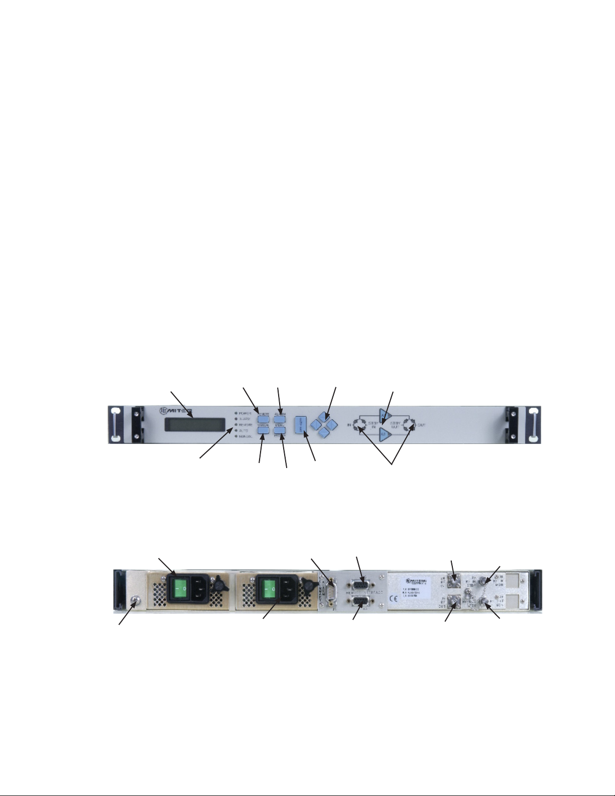
Figure 1-1. Front View, 1:1 Redundant Line Amplier System 1
Figure 1-2. Rear View, 1:1 Redundant Line Amplier System 1
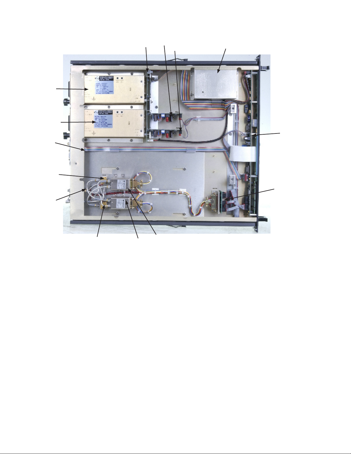
Figure 1-3. Interior View, 1:1 Redundant Line Amplier System 2
Figure 3-1. Automatic Switching Decision Process for a Failed Amplier 7
Figure 3-2. Default Screen 9
Figure 3-3. Example of a Main Menu Screen 10
Figure 3-4. On-LIne/Standby Screen 10
Figure 3-5. Current Monitor Screen 11
Figure 3-6. Voltage Monitor Screen 11
Figure 3-7. Current Limit Screen 11
Figure 3-8. Remote Format Screen 12
Figure 3-9. Static IP Address Screen 13
Figure 3-10. Dynamic IP Address Screen 13
Figure 3-11. Gateway Screen 13
Figure 3-12. Subnet Mask Screen 13
Figure 3-13. Password Screen 14
Figure 3-14. Contrast Adjust Screen 14
Figure 3-15. Priority Screen 14
Figure 3-16. Date/Time Screen 15
Figure 3-17a. Attenuation Screen (RL systems without slope equalization) 15
Figure 3-17b. Attenuation Screen (RL systems with slope equalization)* 15
Figure 3-18. Set Slope Screen* 16
Figure 3-19. Alarm Menu 17
Figure 3-20. Remote/Local Screen 18
Figure 3-21. Manual/Auto Screen 18
Figure 3-22. Login Screen 33
Figure 3-23. Home Screen 34
Figure 3-24. Communications Screen 35
Figure 3-25. Time and Date Screen 36
Figure 3-26. Miscellaneous Settings Page 37
Figure 3-27. Event Log Page 38
Figure 3-28. Logout Page 39
Figure 3-29. Opening Telnet Port 42
Figure 3-30. Telnet Communications 42
Figure 4-1. Block Diagram, Local Control Unit 45
Figure 4-2. Block Diagram, Redundant LNA Unit 46
Figure 5-1. Test Setup for Gain, Gain Ripple and Frequency Response Measurement 53
Table 2-1. External Connections 5
Table 3-1. Summary Alarm Outputs (J1) 28
Table 3-2. 1:1 Status Outputs (Contact Closure) (J2) 29
Table 3-3. Dual 1:1 Status Outputs (Contact Closure) (J2) 29
Table 3-4. 1:2 Status Outputs (Contact Closure) (J2) 30
Table 3-5. Remote Interface Connector (J2) 30
Table 3-6. Ethernet Cable Wiring 31
Table 3-7. General Section - Present In All Products 40
Table 3-8. SNMP - Converter Firmware Doc 171517 41