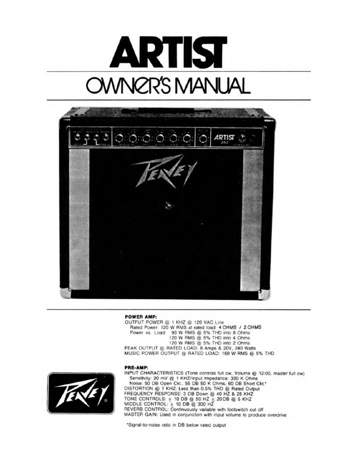
Peavey ARTIST User manual
Other Peavey Amplifier manuals

Peavey
Peavey MAQ 600 User manual

Peavey
Peavey MPT-S2 User manual

Peavey
Peavey XR-700 User manual

Peavey
Peavey XC-400 User manual

Peavey
Peavey Robert Randolph Signature 212 User manual

Peavey
Peavey CS-900 User manual

Peavey
Peavey IA 400 User manual

Peavey
Peavey T.B. RAXX User manual

Peavey
Peavey Vypyr VIP 1 User manual

Peavey
Peavey CS 800S User manual

Peavey
Peavey MA 212T User manual

Peavey
Peavey PV 3800 User manual

Peavey
Peavey UMA 35 T User manual

Peavey
Peavey MPT-X User manual

Peavey
Peavey PV 5300 User manual

Peavey
Peavey KB/A 300 User manual

Peavey
Peavey UMA 150T II User manual

Peavey
Peavey Nashville 400 User manual

Peavey
Peavey Artist V T Series User manual

Peavey
Peavey MMA 835T User manual