4 5
(LENS)
■ 1/4” IT COLOR CCD image sensor
■ Zn die-casting body
■ Compact size
■ Waterproof (IP-67)
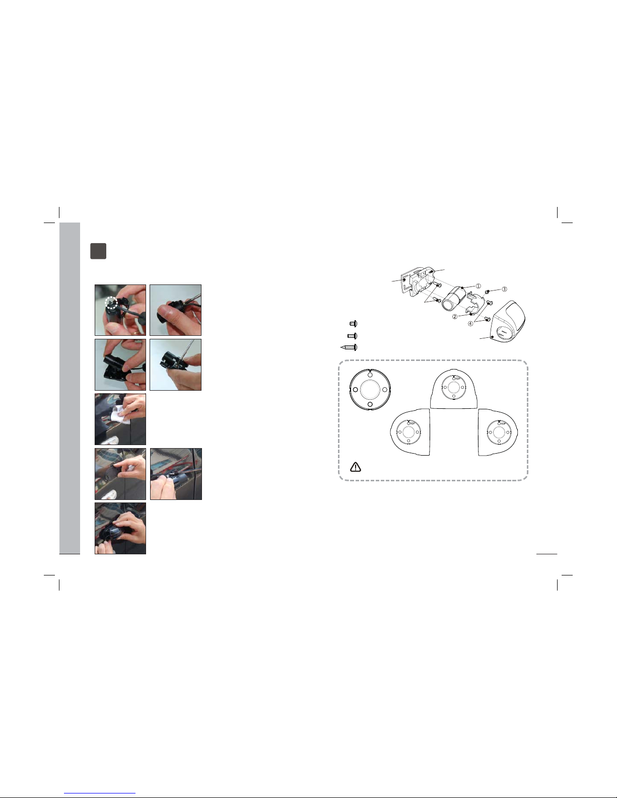
(HOUSING)
■ PC-BODY application
■ Simple assemblling with hook.
1FEATURES
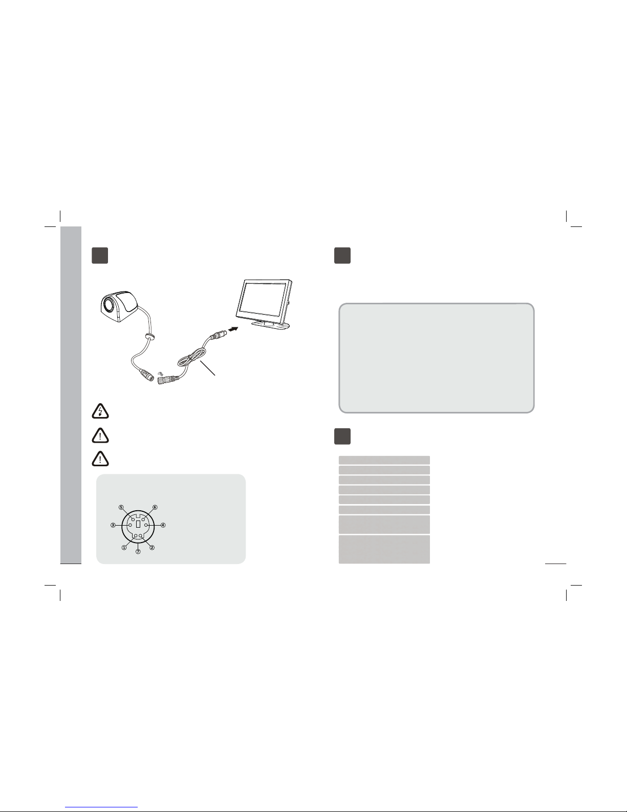
2BOX CONTENTS
Camera Bracket Set
Camera
Instruction
Manual
Bottom Rubber
Extension Cable
15ft (4.6m)
Screws set
WARNING
Please read the “Safety Rules” carefully before using this product. Following the
safety rules prevents users from damages related with the misuse of the product.
It is very important to follow these safety rules. We state “Caution” and “Warning”
to clarify any potential risk for a damage associated with the misuse of the product.
SAFTY RULES
May cause bodily harm or even
death if the user ignores these
warnings in the safety rules.
Warning May cause a damage or shorten
the life time of the product if the
user ignores these cautions in
the safety rules.
Caution
CAUTION
When the power cable cord touches a metal case, cover it with a insulation tape.
--- Short circuit or disconnection of wire may cause a re or accident.
Do not use bolts or nuts from a parts for vehicle.
--- Using bolt or nuts from steering column or break may cause an accident.
Let professional engineers or the sale store install the camera.
--- It require the experience and skills from professional engineers for proper
installation and wiring.
After installing the camera, check it break lamp, head lamp and wipe works
properly.
Install this camera to the vehicle with DC 12V.
Do not dissassemble the device.
--- It may cause a re or malfunction of device.
Do not install the camera projected out from the vehicle.
--- It may harm the pedestriants.
Do not let the extension cable pass through the seat rail. properly wire the
cables.
--- It may cause a re or and accident.
Do not install the camera bracket on the surface of glass.
--- Use the screws to install the camera bracket.