En-2
Electricalspecications
MODEL
NTXFKS09A112A✱
NTXFKS12A112A✱NTXFKS15A112A✱NTXFKS18A112A✱
INDOORUNIT
Powersupply(V,PHASE,Hz) 208/230,1,60
Min.CircuitAmpacity (A) 1.0
Fanmotor(F.L.A.) (A) 0.62 0.72
OUTDOORUNIT
Powersupply(V,PHASE,Hz) 208/230,1,60
Max.Fusesize(timedelay)(A) 15 20
Min.CircuitAmpacity (A) 11 16
Fanmotor(F.L.A.) (A) 0.50 0.93
Compressor (R.L.A.) (A) 8.2 12.0
(L.R.A.) (A) 10.3 15.0
Controlvoltage Indoorunit-Remotecontroller:(Wireless)
Indoorunit-Outdoorunit:DC12-24V(Polar)
Pipe
Outside
diameter
Minimum
wallthick-
ness
Insulation
thickness Insulation
material
inch(mm)
Forliquid
NTXFKS09/12/15/18A112A✱
1/4(6.35) 0.0315
(0.8) 5/16(8) Heatresistant
foamplastic
0.045Specic
gravity
Forgas
NTXFKS09/12A112A✱3/8(9.52) 0.0315
(0.8) 5/16(8)
NTXFKS15/18A112A✱1/2(12.7) 0.0315
(0.8) 5/16(8)
Limits
Pipelength NTXFKS09/12A112A✱65ft.(20m)max.
NTXFKS15/18A112A✱100ft.(30m)max.
Heightdifference NTXFKS09/12A112A✱40ft.(12m)max.
NTXFKS15/18A112A✱50ft.(15m)max.
No.ofbends 10max.
Pipelength
Upto25ft.(7.5m) Noadditionalchargeisrequired.
Exceeding25ft.(7.5m) Additionalchargeisrequired.
(Refertothetablebelow.)
Refrigeranttobe
added
NTXFKS09/12A112A✱1.08ozeach5ft.(20g/m)
NTXFKS15/18A112A✱1.62ozeach5ft.(30g/m)
1-3. SPECIFICATIONS
1-3-1. POWER SUPPLY AND INDOOR/OUTDOOR
WIRE CONNECTION
• Powershouldbetakenfromanexclusivebranchedcircuit.
•
Wiringworkshouldbebasedonapplicabletechnicalstandards.
• Wiringconnectionsshouldbemadefollowingthediagram.
• Securelytightenscrews.
Connecting wires and the ground wire
• UsesolidconductorMin.AWG14orstrandedconductor
Min.AWG14.
• Usedoubleinsulatedcopperwirewith600Vinsulation.
• Usecopperconductorsonly.
*Followlocalelectricalcodes.
Power supply cable and ground wire
• Usesolidorstrandedconductor.
NTXFKS09/12A112A✱Min.AWG14
NTXFKS15/18A112A✱Min.AWG12
• Usecopperconductorsonly.
*Followlocalelectricalcodes.
Note:
Whentheindoorunitispoweredfromtheoutdoorunit,depend-
ingonlocalcode,adisconnectswitchneedstobeinstalledtoa
powersupplycircuit.
1-3-2.REFRIGERANTPIPES
• Topreventcondensation,insulatethetworefrigerantpipes.
• Refrigerantpipebendingradiusmustbe4in.(100mm)ormore.
CAUTION
Besuretousetheinsulationofspeciedthickness(tableonthe
right).Excessiveinsulationmaycauseincorrectinstallationof
theindoorunit,andtoolittleinsulationmaycausecondensate
toform.
• Theunithasaredconnectionsonbothindoorandoutdoor
sides.
• Removethevalvecoverfromtheoutdoorunit,thenconnect
thepipe.
• Refrigerantpipesareusedtoconnecttheindoorandoutdoor
units.
• Becarefulnottocrushoroverbendthepipeinpipebending.
• Refrigerantadjustment...Ifpipelengthexceeds25ft.(7.5m),
additionalrefrigerant(R410A)chargeisrequired.
(Theoutdoorunitischargedwithrefrigerantforpipelengthup
to25ft.[7.5m])
1-2.SELECTINGTHEINSTALLATIONLOCATION
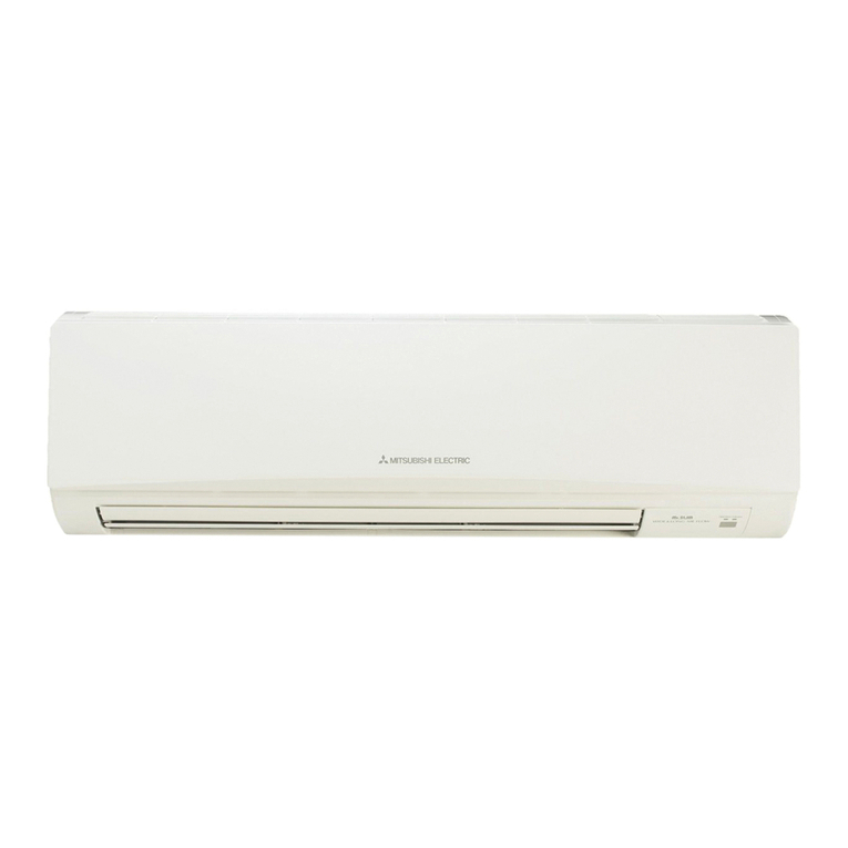
INDOOR UNIT
• Whereairowisnotblocked.
• Whereairspreadsovertheentireroom.
• Rigidwallandatoorwithoutvibration.
• Whereit is notexposedtodirectsunlight.Donot
exposetodirectsunlightalsoduringtheperiodfol-
lowingunpackingtobeforeuse.
• Whereeasilydrained.
• Atadistance3 ft. (1 m)ormoreaway from your
TVandradio.Operationoftheairconditionermay
interferewithradioorTVreception.Anampliermay
berequiredfortheaffecteddevice.
• Inaplaceasfarawayaspossiblefromuorescent
andincandescentlights.Inordertomaketheinfrared
remotecontroloperatetheairconditionernormally.
Theheatfromthelightsmaycausedeformationor
theultravioletmaycausedeterioration.
• Wheretheairltercanberemovedandreplaced
easily.
• Whereitisawayfromtheotherheatorsteamsource.
REMOTE CONTROLLER
• Whereitiseasytooperateandeasilyvisible.
• Wherechildrencannottouchit.
• Selectthepositionwheretheindoorunitcanreceive
thesignalfromtheremotecontrollerproperly.Check
thatsignalsfromtheremotecontrolleraresurelyre-
ceivedbytheindoorunitfromthatposition(‘beep’or
‘beepbeep’receivingtonesounds).Afterthat,attach
remotecontrollerholdertoapillarorwallandinstall
wirelessremotecontroller.
Note:
Inroomswhereinvertertypeuorescentlampsare
used,thesignalfromthewirelessremotecontroller
maynotbereceived.
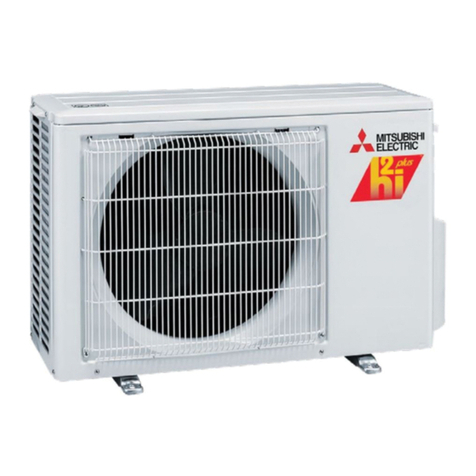
OUTDOOR UNIT
• Whereitisnotexposedtostrongwind.
• Whereairowisgoodanddustless.
• Whererainordirectsunlightcanbeavoidedasmuch
aspossible.
• Whereneighboursarenotannoyedbyoperation
soundorhotair.
• Whererigidwallorsupportisavailabletoprevent
theincreaseofoperationsoundorvibration.
• Wherethereisnoriskofcombustiblegasleakage.
• Wheninstallingtheunitatahighlevel,besureto
securetheunitlegs.
• Whereitisatleast10ft.(3m)awayfromtheantenna
ofTVsetorradio.Operationoftheairconditionermay
interferewithradioorTVreceptioninareaswhere
receptionisweak.Anampliermayberequiredfor
theaffecteddevice.
• Installtheunithorizontally.
• Pleaseinstallitinanareanotaffectedbysnowfall
orblowingsnow.Inareaswithheavysnow,please
install a canopy, a pedestaland/orsomebafe
boards.
Note:
Itisadvisabletomakeapipingloopnearoutdoorunit
soastoreducevibrationtransmittedfromthere.
Note:
Whenoperatingtheairconditionerinlowoutside
temperature,besuretofollowtheinstructions
describedbelow.
• Neverinstalltheoutdoorunitinaplacewhereitsair
inlet/outletsidemaybeexposeddirectlytowind.
• Topreventexposuretowind,installtheoutdoor
unitwithitsairinletsidefacingthewalland
abafe
boardontheairoutletside.
Avoidthefollowingplacesforinstallationwhereair
conditionertroubleisliabletooccur.
• Whereammablegascouldleak.
• Wherethereisanexcessiveamountofmachine
oilintheair.
• Whereoilissplashedorwheretheareaislled
withoilysmoke(suchascookingareasandfac-
tories,inwhichthepropertiesofplasticcouldbe
changedanddamaged).
• Saltyplacessuchastheseaside.
• Wheresuldegasisgeneratedsuchashotspring,
sewage,wastewater.
•
Wherethereis high-frequency orwirelessequip-
ment.
• WherethereisemissionofhighlevelsofVOCs,
includingphthalatecompounds,formaldehyde,
etc.,whichmaycausechemicalcracking.
BH79A443H01_01En.indd 2 2018/07/25 10:02:09


