MIXER OPTIMIX 20 User manual

Instruction Manual Optimix 10 Mixer Technology srl pag.2
GENERAL INDEX
CE MARKING .......................................................................................... 3
FINAL TESTING AND COMMISSIONING ...................................................... 3
RESERVED RIGHTS ................................................................................. 3
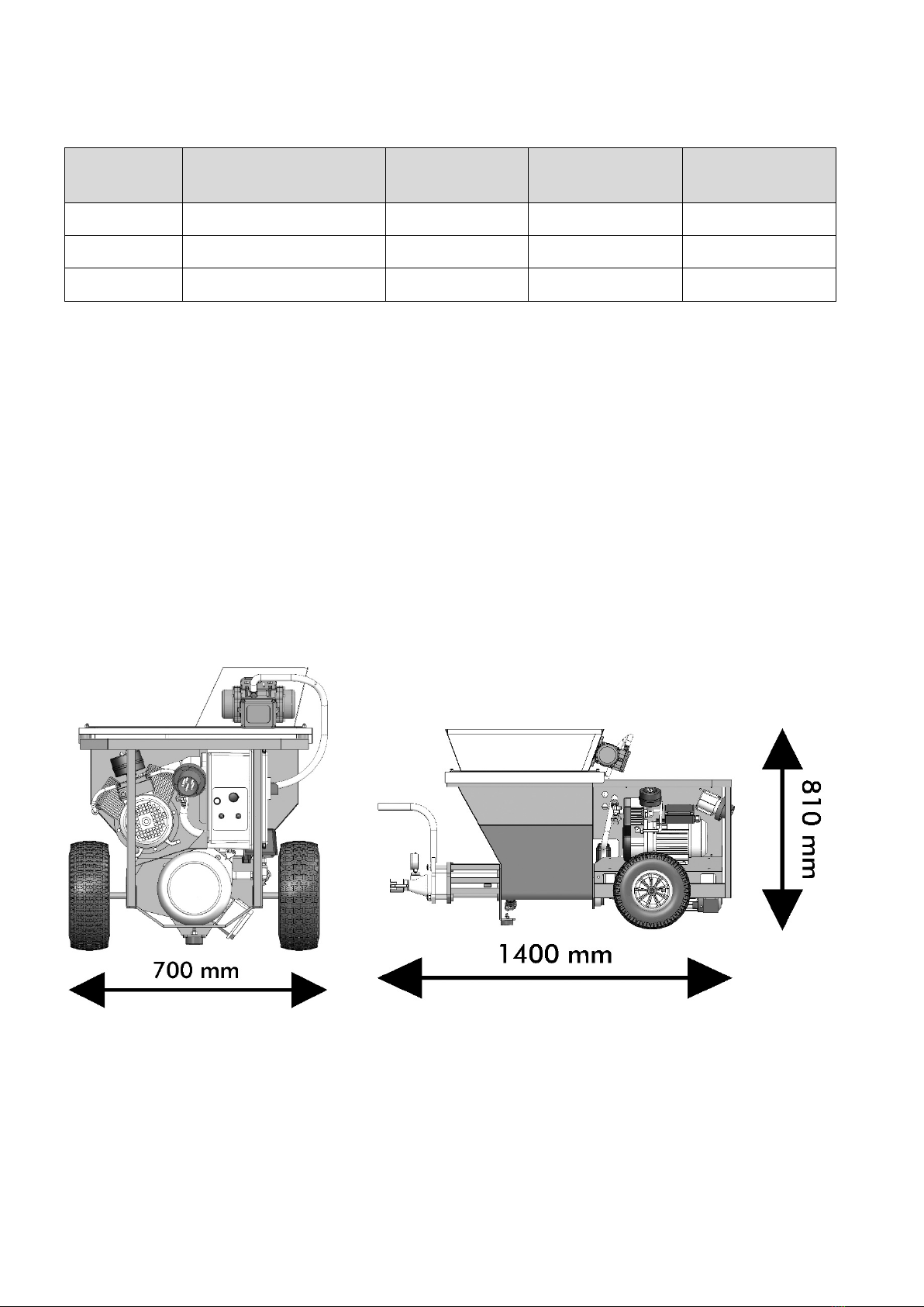
TECHNICAL DATA.................................................................................... 4
DIMENSIONS OF THE MACHINE ................................................................ 4
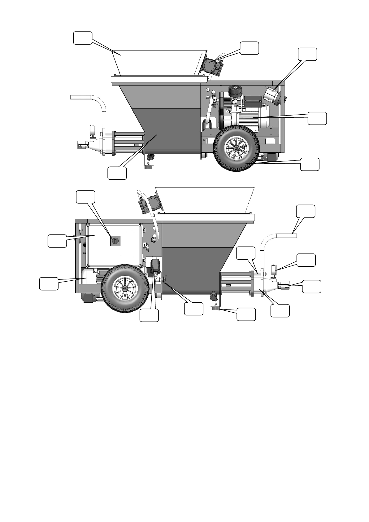
PARTS LIST ............................................................................................ 5
PACKAGING............................................................................................ 6
UNPACKING ........................................................................................... 6
USE DESTINATION .................................................................................. 7
DISPOSAL .............................................................................................. 7
MACHINE TRANSPORT ............................................................................. 7
SAFETY INSTRUCTIONS ........................................................................... 8
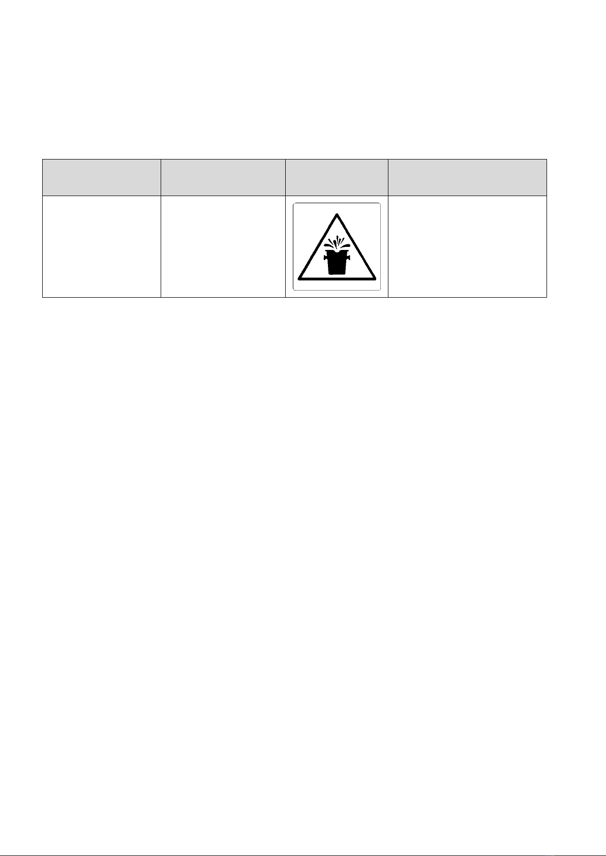
RESIDUAL RISKS .................................................................................... 9
FORESEEABLE INCORRECT USE ................................................................ 9
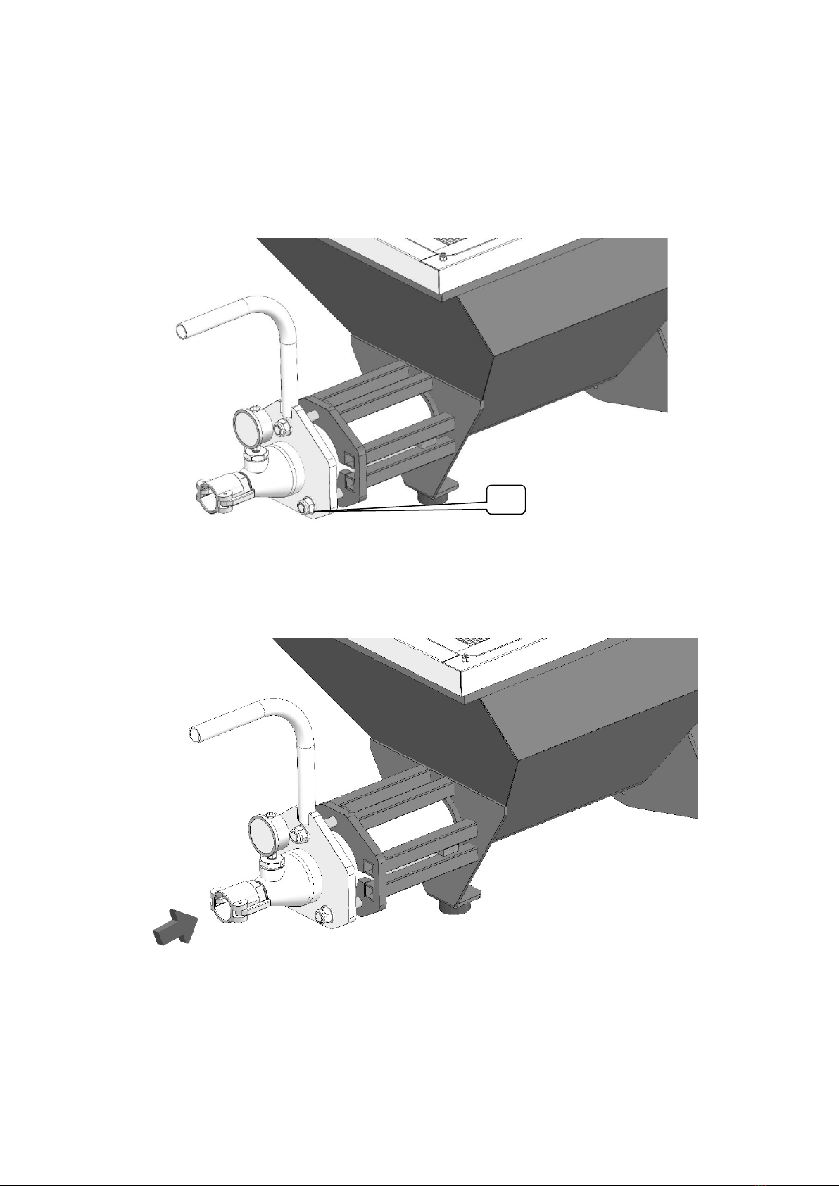
DIASSEMBLING OF ROTOR AND MIXER.....................................................10
CONNECTION OF THE MATERIAL CONVEYING TUBE ...................................10
CONNECTION OF THE AIR TUBE TO THE MACHINE .....................................11
CONNECTION OF THE MATERIAL CONVEYING AND AIR TUBES TO THE
SPRAYING NOZZLE.................................................................................11
ELECTRICAL CONNECTIONS ....................................................................12
CONTROL PANEL ....................................................................................13
CHECKS BEFORE SWITCHING ON.............................................................14
MACHINE PREPARATION .........................................................................14
LOADING MATERIAL IN THE HOPPER ........................................................14
SPRAYING OF THE MATERIAL ..................................................................15
MACHINE SWITCHING OFF ......................................................................15
RESEARCH OF MALFUNCTIONS ................................................................16
ROUTINE MAINTENANCE.........................................................................17
WARRANTY ...........................................................................................18

Instruction Manual Optimix 10 Mixer Technology srl pag.3
CE MARKING
FINAL TESTING AND COMMISSIONING
(by the Manufacturer or the authorized Dealer)
The machine is already tested at the Manufacturer's premises.
The commissioning of the machine at the client is carried out by Manufacturer
or the Authorized Dealer.
At the end of the testing, the Manufacturer or Authorized Dealer fills in the
testing and commissioning certificate, which is signed by the testing
technician, the operator in charge (or any other authorized operator), and by
the safety manager, who shall certify the positive result of the same.
RESERVED RIGHTS
The contents on this manual can’t be reproduced and disclosed (totally or
partially) without written authorization of the Manufacturer.

Instruction Manual Optimix 20 Mixer Technology srl pag.4
TECHNICAL DATA
The models available of the machine: MIXING PUMP OPTIMIX 20
MODELS POWER SUPPLY MOTOR
POWER
SPRAYING
FLOW RATE
MAX.
PRESSURE
2,2 kW 230 V 50 Hz 2,2 kw 0 to 17 L/min 3.5 bar
3 kW 230 V 50 Hz 2,2 kw 0 to 17 L/min 3.5 bar
5,5 kW 230 V 50 Hz 5,5 kW 0 to 50 L/min 3.5 bar
Protection grade of switchboard: IP44
Flow rate: 0 a 17 L/min
Hopper capacity: 80 litres
Max. served distance: 40 meters (*)
Weighted noise pressure level “A”: 92 dB
(*) depending on the characteristics of the product used, the stator, the rotor, the diameter and length of the hose, the spraying
height and the ambient temperature.
DIMENSIONS OF THE MACHINE

Instruction Manual Optimix 20 Mixer Technology srl pag.5
PARTS LIST
1. Wheels
2. Compressor
3. Hopper
4. Hopper protection grid
5. Vibrating screen motor
6. Main power supply plug
7. Electrical panel
8. General electric switch
9. Motor
10. Pressure swicth
11. Air outlet connection
12. Front support foot
13. Stator/rotor group
14. Stator fixing rods (rotor)
15. Material outlet connection
16. Material outlet pressure gauge
17. Movement handle
1
2
6
5
4
3
7
9
8
10
11
12
13
15
16
14
17

Instruction Manual Optimix 20 Mixer Technology srl pag.6
PACKAGING
Usually the machine is packaged by the Manufacturer on wooden pallet, fastened with
straps and wrapped with a film.
List of supplied components:
No. 1 spray lance;
No. 1 Material conveying tube (Strike variable section - L= 20 m);
No. 1 Air tube (ø est. 19 mm - L= 21 m);
No. 1 Instructions for use and maintenance;
No. 1 "Anti-grip" liquid bottle with sprayer (rotor mounting);
No. 1 Rotor / stator group;
No. 1 air tube cleaner tool for spray lance;
No. 1 Diffuser rubber spare parts (nozzle) for spray lance;
No. 1 Sponge rubber balls for cleaning the material transport tube.
UNPACKING
1) Remove the protective film;
2) With a proper tool, cut the straps paying attention not to be hit by the same due to
their elasticity;
3) With the help of a second operator, let the machine carefully get off the pallet
lifting it using the proper handles positioned on the machine sides;

Instruction Manual Optimix 20 Mixer Technology srl pag.7
USE DESTINATION
The use destination of the machine is to use in building sector for the Mixing and
spraying of pre-mixed products having a max. granulometry of 3 mm, suitable for
plastering.
Can be used for the processing: Pre-mixed plasters, dry or in silo, having as base:
plaster, plaster lime, cement lime, finishing plasters, stoppers, coloured plasters,
gluing agents in general, foundation for floors and mortars.
Any other different use is potentially inappropriate.
DISPOSAL
At the disposal time of the machine, compulsorily observe the provisions of the
regulations in force.
Separate the parts making up the machine according to the different construction
materials (plastic, copper, iron, etc...).
Lubricant liquids and any other fluids shall not be dispersed in the
environment.
These products, deemed polluting and hazardous, shall be compulsory disposed
entrusting companies authorized and specialized for the different types of product.
MACHINE TRANSPORT
Use the handle No.17 indicated in the chapter PARTS LIST, at pages 6, for
transportation and lifting.

Instruction Manual Optimix 20 Mixer Technology srl pag.8
SAFETY INSTRUCTIONS
1. The machine use is only reserved to qualified and trained staff in according to
the safety provision law.
2. Always remove the voltage, turning off master switch, before to do any
operation on the machine.
3. The master switch has also the stop emergency function in case of necessity.
4. Conform to use destination of the machine described in the in the specific
chapter.
5. The disconnection of the material conveying tube, it is compulsory to done only
with pressure at zero of pressure gauge.
6. Consult the instructions of pre-mixed products, before to use the machine
7. The machine is not suitable to use in environments with potentially explosive
atmospheres (Atex)
8. Only one operator at time on the machine
9. The machine has not been conceived for to transport and/or lift persons and
things.
10. Pay attention to transport the machine on slopes, danger to be run over
11. It is absolutely forbidden to tamper, disconnect and/or remove any safety
device existing in the machine.
12. For the safe use of the machine are recommended the following personal
protective equipment: safety footwear, protective gloves from chemicals,
goggles or face shield, earmuff.
13. Don’t introduce objects thought the hopper protection grating. Don’t use the
machine with the open grating.
14. It is absolutely forbidden to tamper the calibration of pressure reduction valve.
15. Don’t step or pull tubes and the electrical connections.

Instruction Manual Optimix 20 Mixer Technology srl pag.9
RESIDUAL RISKS
The machine was designed and produced to compliance with current legislation at state
of art.
However, the machine presents residual risks, risks that can’t be eliminated at the
source and involving a training and the operator’s attention.
ZONE RESIDUAL
RISKS DANGER PREVENTIVE
MEASURES
Material
conveying tube
hazard to be hit
by the ejection of
material subject
to pressure.
Education, training.
The tubes
disconnection only in
the absence of pressure
indicated in gauge.
FORESEEABLE INCORRECT USE
Don’t use different products from the Antigrip, supplied, for danger of malfunctions of
the machine.
Don’t throw foreign body in hopper (gravel, stones, etc….) for danger of machine
breakdown and dangerous projection.

Instruction Manual Optimix 20 Mixer Technology srl pag.10
DIASSEMBLING OF ROTOR AND MIXER
Carry out the operations by following the letters in succession:
1. Remove the voltage to the electrical panel;
2. Unscrew the screws no. 1;
3. Remove the pump unit (flange with pressure gauge, stator, and rotor from the
hopper);
4. Unscrew the rotor from the stator.
Attention:
Spray the Antigrip on the rotor BEFORE install in the stator.
CONNECTION OF THE MATERIAL CONVEYING TUBE
Attention:
Performing the disconnection only in the absence of pressure indicated in gauge.
1

Instruction Manual Optimix 20 Mixer Technology srl pag.11
CONNECTION OF THE AIR TUBE TO THE MACHINE
CONNECTION OF THE MATERIAL CONVEYING AND AIR TUBES
TO THE SPRAYING NOZZLE

Instruction Manual Optimix 20 Mixer Technology srl pag.12
ELECTRICAL CONNECTIONS
Verify that the starter electrical connections, is complies to the legislation in force
in electrical connections safety area (marking CE).
The machine is not suitable to connect to power supply outlets of house systems.
Verify to provide voltage and power appropriate to the machine.
Verify that thermal magnetic circuit breaker protection and residual current
protection (life saver) is installed.
All the electrical connections (plugs - sockets) must be CEE industrial type with
protection degree IP67.
The use of extension cords is admitted only if made in safety standards (cross-
section of conductors, insulation, earthing, etc.)

Instruction Manual Optimix 20 Mixer Technology srl pag.13
CONTROL PANEL
REF. COMMAND FUNCTION
1 3-position selector
“Start/Stop”
Pos “O”: Maintained for more than 3 seconds stop
the machine;
Pos. “Return”: return position;
Pos “I-Run”: Maintained for more than 3 seconds
it starts the machine;
2 3-position selector
DX: Reverses the direction of mixer rotation
0: Return of the selector
SX: Direction of rotation for the pumping phase
3 Potentiometer Adjusts the motor speed
4 Voltage led On indicates the presence of voltage in the panel
3
2
4
1

Instruction Manual Optimix 20 Mixer Technology srl pag.14
CHECKS BEFORE SWITCHING ON
1) Make sure that there are not any non-authorized persons close to the
machine.
2) Make sure that the machine is positioned and in horizontal plane.
3) Make sure that all components are properly installed.
4) Make sure that the safety devices are integral, properly installed and
working.
5) Make sure that all shelves are correctly closed.
6) Make sure that the plug of the power supply cable is connected to the plant
supplier and that the main electric switch is off.
7) Make sure that the air, water and material conveying tubes are well
stretched avoiding any constriction.
8) Use the compulsory personal protective devices provided by own employer.
9) Verify the filter presence, if the water isn’t being drawn from water supply.
MACHINE PREPARATION
1. Pour about 10 litres of clean water into the hopper with a suitable container and /
or hoses;
2. Move the gearmotor speed variator to pos. 50%;
3. Start the machine by turning the selector to pos. "March";
4. When the water level in the hopper reaches the mixer, stop the machine by turning
the selector to pos. "Stop";
LOADING MATERIAL IN THE HOPPER
Load the material inside the hopper according to the available equipment (Ex: shovel,
wheelbarrow, mixer machine for like "Betomix, Mixer 50, etc ...").
N.B.: IT IS STRICTLY FORBIDDEN TO LOAD PRODUCT WITH A
GRANULOMETRY BIGGER THAN 2.5 mm.
N.B.: IT IS STRICTLY FORBIDDEN TO INTRODUCE, THROUGH THE
PROTECTION GRID, ANY OBJECT AND / OR TOOL IN THE HOPPER.

Instruction Manual Optimix 20 Mixer Technology srl pag.15
SPRAYING OF THE MATERIAL
1) Hold the spraying nozzle and direct it against the surface to be worked;
2) Open (+) the valve “V” (Fig. B) on the spraying nozzle;
3) For the mortar lance adjust the spraying of the material moving forwards
and/or backwards (+ or -), the air tube acting on the screw and blocking it in
the correct position;
4) To minimize the deterioration of stator/rotor group, avoid useless stops and
restarts of spray;
5) During work breaks less than 15 minutes, close the valve on the spraying
6) In case of clogged of material conveying tube, enabling the mixer reverse run
selector for the time needed;
MACHINE SWITCHING OFF
1) Closing the valve on the lance mortar spraying nozzle or releases the lever for
lance for glues;
2) After every shutdown, carry out the machine cleaning;
V

Instruction Manual Optimix 20 Mixer Technology srl pag.16
RESEARCH OF MALFUNCTIONS
The operations of research and remove of malfunctions must be done only by
competent and experienced staff.
All the intervention operations must be done in the absence of voltage.
NR ANOMALIES
CAUSES
SOLUTIONS
1 The machine does
not start.
Power supply
Verify the connections of outlets
and plugs
2 The gearmotor
does not start.
1) tap of the
spraying nozzle
closed;
2) nozzle of the
spraying nozzle
clogged;
1) open the tap of the spraying
nozzle;
2) carefully clean the nozzle of
the spraying nozzle;
3 The compressor
stops – thermal
protection
tripping
1) mechanical break
of the compressor
(with rod
malfunction);
2) clogged suction
filters;
3) cable or plug
damaged.
1) visible from outside (request
technical assistance);
2) replace the filters;
3) check cable and plug and
replace, if necessary.

Instruction Manual Optimix 20 Mixer Technology srl pag.17
ROUTINE MAINTENANCE
The operations of routine maintenance must be done only by competent and
experienced staff.
The replacement of the machine components must be carried out only with original
spare parts.
FREQUENCY AREA INTERVENTION
Every 10-15 hours
of work
Rotor (screw) stator
(plenum chamber) used
with cement products.
Replacement
Every 30-40 hours
of work
Rotor (screw) stator
(plenum chamber) used
with gaseous products.
Replacement
Every 100-150
hours of work
Mixer Replacement
Daily
Safety devices Functional verification
Material conveying tube,
air tube and power
supply cable.
Visual inspection of tear
status.
Weekly Gearmotor. Visual inspection and, if
necessary, topping up with
oil type BERGOIL
“BERGOFLUID 1000” or
equivalent.
Compressor filter. Cleaning
Six-monthly Compressor filters. Replacement
Grease gun on flange
gearmotor.
Adding grease
Biennial Material conveying tube Replacement

Instruction Manual Optimix 20 Mixer Technology srl pag.18
WARRANTY
1) Within the limits set forth by this warranty, the undersigned manufacturer
undertakes to repair all possible construction damages that may arise during the warranty
period of 12 (twelve) months for a daily use of 8 (eight) working hours. Such term shall
elapse as follows:
a) From the delivery date (Ref. transport document and sale invoice), if the
machine is sold directly to the Customer;
b) From the date given on the “Testing and Commissioning Certificate”, if the
Manufacturer or the Authorized Dealer performs the testing and commissioning of the
machine;
c) From the date of sale (Ref. transport document and sale invoice), if the machine is sold
directly by an Authorized Dealer on a "sale or return" basis; The obligations resulting from
the warranty decay in case of suspension or modification of the payment terms agreed
upon.
2) The warranty decays, if the purchaser does not duly observe the provisions
described in the “Instructions for Use and Maintenance” of the machine.
3) Remain excluded from the warranty: Failures and defects due to the normal tear of
those parts, which for their nature are subject to rapid and fast tear; electric
equipment; failures resulting from the use of tools and accessories not directly supplied
by the manufacturer.
4) In order to be able to exercise the warranty right, the purchaser has to inform the
manufacturer in case of defect detection immediately and, in any case, not later than 8
(eight) days from the detection date; moreover, it has to allow, if deemed necessary by
the same, the performance of the related inspections and repairing interventions.
5) The shipment of the faulty part, covered by the warranty, to the manufacturer for the
repairing or replacement of the same is at purchaser's charge. The warranty obligations,
as foreseen by this clause, are deemed fulfilled with the delivery to the purchaser of the
part duly repaired or replaced.
6) During the warranty period set forth by clause 1) labour costs, for the exclusive
duration of the intervention, are at manufacturer’s charge.
Should the repairing or replacement procedures be carried out where the machine is
installed, travel and lodging expenses of the personnel are at purchaser's charge.
7) Remain in any case excluded from the warranty, all faults caused by wrong
manoeuvre, negligence, fortuitous event or in any case all faults imputable to the user, in
person or through third parties, or when the purchaser has carried out modifications or
repairing interventions without the written consent of the manufacturer, independently
from the connection of such modifications or repairing interventions with the detected
faults.
8) It is explicitly agreed upon, that the manufacturer shall not be held responsible for any
liability following any possible damages that the purchasers may suffer resulting from loss
of or diminished production due to possible construction defects subject to this warranty.

Instruction Manual Optimix 20 Mixer Technology srl pag.19
Thank you for choosing our product
MIXER TECHNOLOGY srl
Via dei Carabinieri, 45, 36040
Torri di Quartesolo (VI) Italy
www.mixersrl.com
Table of contents
Other MIXER Water Pump manuals
Popular Water Pump manuals by other brands

IceManCooler
IceManCooler ICE-D50 user guide

Kamoer
Kamoer KSP-F01A user manual

SKF
SKF Lincoln PFHM-EEX operating instructions

HST
HST EPS Series Installation and operating instruction

Xtreme Power
Xtreme Power 46021 Owner's manual and safety instructions

Newa Pond
Newa Pond CST adv 2300 Instructions and guarantee

Westfalia
Westfalia 93 78 16 Original instructions

Grundfos
Grundfos APG Series Installation and operating instructions

Grundfos
Grundfos Sololift2 CWC-3 Installation and operating instructions

Grundfos
Grundfos KPL.700-1400 Service instructions

XINDAO
XINDAO XD P239.572 manual

Teral
Teral VKA Series instruction manual