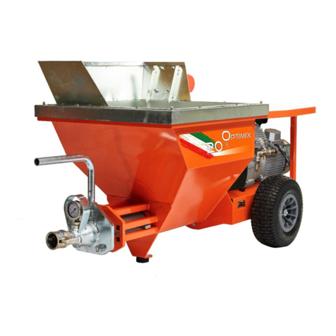
MIXER PLUS MONO TOP User manual

MIXING PUMP MIXER PLUS
MANUAL INSTRUCTIONS
ORIGINAL INSTRUCTIONS
Revision n…… of ……
MIXER TECHNOLOGY srl
Via dei Carabinieri, 45, 36040
Torri di Quartesolo (VI) Italy
www.mixersrl.com

Instruction Manual Mixer Plus Mixer Technology srl pag.2
GENERAL INDEX
CE MARKING................................................................................................................. 3
FINAL TESTING AND COMMISSIONING ............................................................................ 3
RESERVED RIGHTS........................................................................................................ 3
TECHNICAL DATA .......................................................................................................... 4
DIMENSIONS OF THE MACHINE....................................................................................... 4
PARTS LIST .................................................................................................................. 6
PACKAGING .................................................................................................................. 7
UNPACKING .................................................................................................................. 8
USE DESTINATION ........................................................................................................ 8
DISPOSAL .................................................................................................................... 8
MACHINE TRANSPORT.................................................................................................... 9
SAFETY INSTRUCTIONS ............................................................................................... 10
RESIDUAL RISKS......................................................................................................... 11
FORESEEABLE INCORRECT USE .................................................................................... 11
ASSEMBLING OF ROTOR AND MIXER ............................................................................. 12
WATER CONNECTION................................................................................................... 14
CONNECTION OF THE MATERIAL CONVEYING TUBE ......................................................... 14
CONNECTION OF THE AIR TUBE TO THE COMPRESSOR .................................................... 15
CONNECTION OF THE MATERIAL CONVEYING AND AIR TUBES TO THE SPRAYING NOZZLE... 15
ELECTRICAL CONNECTIONS.......................................................................................... 16
CONTROL PANEL ......................................................................................................... 17
PLUS-MONO MODEL..................................................................................................... 17
PLUS-TOP MODEL ........................................................................................................ 18
PLUS CLASSIC and STANDARD ELECTRICAL PANEL ......................................................... 19
CHECKS BEFORE SWITCHING ON .................................................................................. 21
MACHINE PREPARATION............................................................................................... 22
SPRAYING OF THE MATERIAL........................................................................................ 24
MACHINE SWITCHING OFF ........................................................................................... 24
CLEANING OF CHAMBER MIXING................................................................................... 25
CLEANING OF THE HOPPER........................................................................................... 26
CLEANING OF THE SPRAYING NOZZLE AIR TUBE............................................................. 27
SWATER DRAINAGE DURING WINTER PERIOD ................................................................ 27
RESEARCH OF MALFUNCTIONS ..................................................................................... 28
ROUTINE MAINTENANCE .............................................................................................. 30
REPLACEMENT OF THE ROTOR STATOR .......................................................................... 31
WARRANTY ................................................................................................................. 32
NOTES ....................................................................................................................... 33

Instruction Manual Mixer Plus Mixer Technology srl pag.3
CE MARKING
FINAL TESTING AND COMMISSIONING
(by the Manufacturer or the authorized Dealer)
The machine is already tested at the Manufacturer's premises.
The commissioning of the machine at the client is carried out by Manufacturer
or the Authorized Dealer.
At the end of the testing, the Manufacturer or Authorized Dealer fills in the
testing and commissioning certificate, which is signed by the testing
technician, the operator in charge (or any other authorized operator), and by
the safety manager, who shall certify the positive result of the same.
RESERVED RIGHTS
The contents on this manual can’t be reproduced and disclosed (totally or
partially) without written authorization of the Manufacturer.

Instruction Manual Mixer Plus Mixer Technology srl pag.4
TECHNICAL DATA
The models available of the machine: MIXING PUMP MIXER PLUS
MODELS POWER SUPPLY POWER
WATER SUPPLY
PLUS MONO 2,2 KW 2 x 230 Volt 3,7 kw Water
PLUS MONO 3 KW 2 x 230 Volt 3,7 kw Water
PLUS MONO STANDARD 3 x 400 Volt 7,4 kw Water
PLUS MONO TOP 3 x 400 Volt 7,4 kw Water
PLUS MONO CD25 3 x 400 Volt o 2 x 230
Volt
3,7/7,4
kw
Water
PLUS CLASSIC 3 x 400 Volt 7,4 kw Water
Operating temperature: minimum+5°C, maximum +35°C
Protection grade of switchboard: IP44
Water pump flow rate: 40 litres/min
Compressor air flow rate: 240 litres /min
Flow rate: 6-50 litres /min
Hopper capacity: 80 litres
Max. served distance: 40 meters
Weighted noise pressure level “A”: 92 dB
If the withdraw water is from a deposit, tub or well, it’s required insert a cleaner
upline of the machine.
Accessories upon request: Fairing for feeding from silo
DIMENSIONS OF THE MACHINE
MODELS DIMENSIONS (cm) WEIGHT
(without tubes)
PLUS MONO 2,2 KW A=155 B=110 C=66 215 kg
PLUS MONO 3 KW A=155 B=110 C=66 215 kg
PLUS STANDARD A=155 B=110 C=72 240 kg
PLUS TOP A=155 B=110 C=72 240 kg
PLUS CD25 A=155 B=110 C=72 240 kg
PLUS CLASSIC A=155 B=110 C=72 240 kg
A= Height B= Width C= Depth

Instruction Manual Mixer Plus Mixer Technology srl pag.5
1
2
3
4
5
6
7
8
13
9
10
11
12
14
15
16
17
18
20
21
22
23
24
25
14
1
10
9
26
3
25
27
19

Instruction Manual Mixer Plus Mixer Technology srl pag.6
PARTS LIST
1. Mixing chamber locking lever
2. Hopper protection grid with bag cutting blade
3. Compressor
4. Hopper discharge door
5. Water pump
6. Water inlet
7. Cell wheel gearmotor
8. Service tap
9. Pivoting wheels
10. Lifting handles
11. Water pressure reduction unit
12. Water line pressure gauge
13. Water adjustment valve
14. Mixing assembly gearmotor
15. Water inlet in the mixing chamber (light products)
16. Water inlet in the mixing chamber (all products, except for light ones)
17. Flow meter
18. Water drain tap
19. Stator (plenum chamber)
20. Material output connection
21. Material output pressure gauge
22. Gearmotor power supply outlet (only mod. Plus Mono)
23. Trunket
24. Mixing chamber
25. Gearmotor assembly locking device
26. Main power supply plug
27. Rear connection points for the fairing

Instruction Manual Mixer Plus Mixer Technology srl pag.7
PACKAGING
Usually the machine is packaged by the Manufacturer on wooden pallet, fastened with
straps and wrapped with a film.
List of supplied loose components:
No. 1 Mixer;
No. 1 Rotor;
No. 1 "T" wrench;
No. 1 Spraying nozzle;
No. 1 Material conveying tube (ø est. 39 mm - L= 15 m);
No. 1 Air tube (ø est. 19 mm - L= 16 m);
No. 1 Water tube (ø est. 26 mm - L= 40 m);
No. 1 Power supply cable with outlet, without plug (L= 50 m).
Components positioned in the tool carrying box
No. 1 Instructions for use and maintenance;
No. 1 "Anti-grip" liquid bottle with sprayer;
No. 1 Cleaning device;
No. 1 Spraying nozzle air tube cleaning tool;
No. 1 Screwdriver;
No. 1 Fixed wrench (2 sizes 24 - 36 mm);
No. 1 Fixed wrench (3 sizes 30 - 13 - 10 mm);
No. 2 Diffuser rubber spare (nozzle) parts for spraying nozzle;
No. 2 Small foam rubber balls to clean the material conveying tube;
No. 2 Water tube fittings;
No. 2 Water tube clamps;
No. 2 Fittings (reduction units) for water inlet (1" - 3/4");
No. 1 Fast connection for cleaning the material transport tube;
No. 1 Cleaning device rod.

Instruction Manual Mixer Plus Mixer Technology srl pag.8
UNPACKING
1) Remove the protective film;
2) With a proper tool, cut the straps paying attention not to be hit by the same due to
their elasticity;
3) Release the brake of the pivoting wheel;
4) With the help of a second operator, let the machine carefully get off the pallet
lifting it using the proper handles positioned on the machine sides;
5) Lock the brake of the pivoting wheel.
USE DESTINATION
The use destination of the machine is to use in building sector for the Mixing and
spraying of pre-mixed products having a max. granulometry of 5 mm, suitable for
plastering.
Can be used for the processing: Pre-mixed plasters, dry or in silo, having as base:
plaster, plaster lime, cement lime, finishing plasters, stoppers, coloured plasters,
gluing agents in general, foundation for floors and mortars.
Any other different use is potentially inappropriate.
DISPOSAL
At the disposal time of the machine, compulsorily observe the provisions of the
regulations in force.
Separate the parts making up the machine according to the different construction
materials (plastic, copper, iron, etc...).
Lubricant liquids and any other fluids shall absolutely not be dispersed in the
environment.
These products, deemed polluting and hazardous, shall be compulsory disposed
entrusting companies authorized and specialized for the different types of product.

Instruction Manual Mixer Plus Mixer Technology srl pag.9
MACHINE TRANSPORT
In the drawing are visible the coupling points for the transport and handling of the
machine.

Instruction Manual Mixer Plus Mixer Technology srl pag.10
SAFETY INSTRUCTIONS
1. The machine use is only reserved to qualified and trained staff in according to
the safety provision law.
2. Always remove the voltage, turning off master switch, before to do any
operation on the machine.
3. The master switch has also the stop emergency function in case of necessity.
4. Conform to use destination of the machine described in the in the specific
chapter.
5. The disconnection of the material conveying tube, it is compulsory to done only
with pressure at zero of pressure gauge.
6. Consult the instructions of pre-mixed products, before to use the machine
7. The machine is not suitable to use in environments with potentially explosive
atmospheres (Atex)
8. Only one operator at time on the machine
9. The machine has not been conceived for to transport and/or lift persons and
things.
10. Pay attention to transport the machine on slopes, danger to be run over
11. It is absolutely forbidden to tamper, disconnect and/or remove any safety
device existing in the machine.
12. Lock the brake of the pivoting wheel, just finished the movement.
13. For the safe use of the machine are recommended the following personal
protective equipment: safety footwear, protective gloves from chemicals,
goggles or face shield, earmuff.
14. Don’t introduce objects thought the hopper protection grating. Don’t use the
machine with the open grating.
15. It is absolutely forbidden to tamper the calibration of pressure reduction valve.
16. Don’t step or pull tubes and the electrical connections.

Instruction Manual Mixer Plus Mixer Technology srl pag.11
RESIDUAL RISKS
The machine was designed and produced to compliance with current legislation at state
of art.
However, the machine presents residual risks, risks that can’t be eliminated at the
source and involving a training and the operator’s attention.
ZONE RESIDUAL
RISKS DANGER PREVENTIVE
MEASURES
Hopper
protection
grating
Cutting hazard in
case of contact
with the bag
cutting blade
Education, training.
Material
conveying tube
hazard to be hit
by the ejection of
material subject
to pressure.
Education, training.
The tubes
disconnection only in
the absence of pressure
indicated in gauge.
FORESEEABLE INCORRECT USE
Don’t use different products from the Antigrip, supplied, for danger of malfunctions of
the machine.
Don’t throw foreign body in hopper (gravel, stones, etc….) for danger of machine
breakdown and dangerous projection.

Instruction Manual Mixer Plus Mixer Technology srl pag.12
ASSEMBLING OF ROTOR AND MIXER
Carry out the operations by following the letters in succession.
A
B
C
D
E
F
G
Antigrip

Instruction Manual Mixer Plus Mixer Technology srl pag.13
H
I
L
M
N

Instruction Manual Mixer Plus Mixer Technology srl pag.14
WATER CONNECTION
CONNECTION OF THE MATERIAL CONVEYING TUBE
Attention:
Performing the disconnection only in the absence of pressure indicated in gauge.

Instruction Manual Mixer Plus Mixer Technology srl pag.15
CONNECTION OF THE AIR TUBE TO THE COMPRESSOR
CONNECTION OF THE MATERIAL CONVEYING AND AIR TUBES
TO THE SPRAYING NOZZLE
1
2

Instruction Manual Mixer Plus Mixer Technology srl pag.16
ELECTRICAL CONNECTIONS
Verify that the starter electrical connections, is complies to the legislation in force
in electrical connections safety area (marking CE).
The machine is not suitable to connect to power supply outlets of house systems.
Verify to provide voltage and power appropriate to the machine.
Verify that thermal magnetic circuit breaker protection and residual current
protection (life saver) is installed.
All the electrical connections (plugs - sockets) must be CEE industrial type with
protection degree IP67.
The use of extension cords is admitted only if made in safety standards (cross-
section of conductors, insulation, earthing, etc..)

Instruction Manual Mixer Plus Mixer Technology srl pag.17
CONTROL PANEL
PLUS-MONO MODEL
REF. COMMAND FUNCTION
1 Machine Run/Stop
I: automatic run;
Return: neutral position;
0: automatic stop.
2 Warning led state of
machine
Green fixed: stopped;
Red fixed: running;
Orange fixed: minimum voltage;
Green intermittent: lack of water;
Red intermittent: thermal protections
tripping.
3 Cell wheel motor
O: stopped;
I: running.
4 Water pump
UP: automatic run;
O: stopped;
DOWN: manual run.
5 Compressor and
winter drain
UP: run/stop compressor;
O: neutral position;
DOWN: winter drainage.
6 Mixer reverse run
UP: Reverses rotation direction of the
mixer;
O: neutral position.
7 Frequency selection
Left: 50 Hz electric frequency operation;
Centre: 40 Hz electric frequency operation;
Right: 45 Hz electric frequency operation.
3
6
5
4
2
1
7

Instruction Manual Mixer Plus Mixer Technology srl pag.18
PLUS-TOP MODEL
REF. COMMAND FUNCTION
1 Machine Run/Stop
I: automatic run;
Return: neutral position;
0: automatic stop;
By hold the action “O” start the winter drainage.
2 Warning led state
of machine
Green fixed: stopped;
Red fixed: running;
Orange fixed: minimum voltage;
Green intermittent: lack of water;
Red intermittent: thermal protections tripping.
3 Cell wheel motor O: stopped;
I: running.
4 Water pump
UP: automatic run;
O: stopped;
DOWN: manual run.
5
Mixer reverse run
and compressor
run
UP: By hold the action reverses rotation direction
of the mixer;
O: neutral position;
GIU’: stop the compressor.
1
5
4
3
2

Instruction Manual Mixer Plus Mixer Technology srl pag.19
PLUS CLASSIC and STANDARD ELECTRICAL PANEL
1
2
3
4
5
6
7
8
9
10

Instruction Manual Mixer Plus Mixer Technology srl pag.20
REF. COMMAND FUNCTION
1 O Stop machine
2 I Run machine
3 Run Winter drainage
4 Green Led Voltage presence
5 Red Led Tripping of the thermal protection gearmotor
6 Orange Led
Inverted phases
Off = correct phases;
On = incorrect phases, change the position of
the master switch
7 Reverse run Reverses mixer direction motion
8 Water pump
1 = automatic
0 = stopped
2 = manual
9 Cell wheel I = running
O = stopped
10 Main switch
1 = directed phases
0 = panel off
2 = inverted phases
This manual suits for next models
1
Table of contents
Other MIXER Water Pump manuals
Popular Water Pump manuals by other brands

RIDGID
RIDGID R12V Operating instructions & parts manual

Nordson
Nordson BM 200 Operator card

Goulds Pumps
Goulds Pumps DWT Installation, operation and maintenance instructions

Lorentz
Lorentz PSk2 CS-F Series MANUAL FOR INSTALLATION, OPERATION, SERVICE

Whale
Whale Watermaster FW0814 Installation and operation manual

METZGER
METZGER BETA 161 Technical manual