Miyachi DT-350 User manual

1 D
ESK
T
OP
S
ERIES
–
AUTOMATIC OPERATION
USER MANUAL
Desk Top Series – Automatic Operation
Models: DT-350, DT-360, DT-370, DT-450
Manufacturer:
Miyachi Europe Corporation
Schootense Dreef 21
P.O. box 164
NL-5700 AD HELMOND
The Netherlands
Phone: +31 (0) 492 54 22 25
Fax: +31 (0) 492 53 62 22
Internet : www.mec.miyachi.com
User manual specifications: Date: August 2010
Version: 1 S.D.
The following documents are related to this
manual:
•Electrical & Mechanical drawings
•Bond head manuals
•Spare parts list
DT
-
3
50
/ 360 PH
DT
-
350 / 360 PLC
DT
-
3
70
PH
DT
–
450 PLC

2 D
ESK
T
OP
S
ERIES
–
AUTOMATIC OPERATION
Register of changes / Version control table
Table 1: Register of changes
Page
Version
Date
Status
Remarks
All 1.0 August 2010 Released
Various
1.1
December 2011
Released
Options screen dumps for
TD200 added and changes
to illustrations

3 D
ESK
T
OP
S
ERIES
–
AUTOMATIC OPERATION
Copyright © 2011 Miyachi Europe Corporation
The information in this document may be subject to alteration without any obligation to give
prior notification. No part of this publication may be reproduced and/or made public by
means of printing, photocopy, microfilm or in any other way or for any purpose whatsoever,
without the prior, explicit written permission of Miyachi Europe Corporation
Miyachi Europe Corporation. has the right to change parts of the machine at any time
without prior or direct notice to the client. The contents of this publication is subject to
change without notice.
For extra information as to adjustments, maintenance and repair, contact the technical
department of your supplier.
This user manual has been composed with great care. However, Miyachi Europe
Corporation cannot be held responsible either for any shortcomings occurring in this user
manual or for their consequences.
Author: S F Duerden

4 D
ESK
T
OP
S
ERIES
–
AUTOMATIC OPERATION
Contents
1 SAFETY PRECAUTIONS........................................................................................................6
1.1 GENERAL SAFETY PRECAUTIONS..............................................................................6
1.2 WARNINGS ON THE DESKTOP SYSTEM:....................................................................6
2 INTRODUCTION....................................................................................................................8
2.1 GENERAL ........................................................................................................................8
2.2 INTENDED USE..............................................................................................................9
2.3 PRINCIPLE OF OPERATION.......................................................................................10
2.4 SOUND LEVEL..............................................................................................................10
2.5 SYSTEM REQUIREMENTS...........................................................................................10
2.6 SPECIFICATIONS – AIR AND ELECTRICAL SUPPLIES...........................................11
3 CONSTRUCTION .................................................................................................................12
3.1 GENERAL CONSTRUCTION........................................................................................12
3.2 TAPE INTERPOSER MODULE ....................................................................................16
3.3 ACF MODULE...............................................................................................................16
3.4 SAFETY MEASURES AND DEVICES...........................................................................16
3.4.1 Protection guards....................................................................................................16
3.4.2 Hot parts..................................................................................................................16
3.4.3 Electrical safety.......................................................................................................16
3.4.4 Emergency stop .......................................................................................................16
3.5 CERTIFICATION...........................................................................................................17
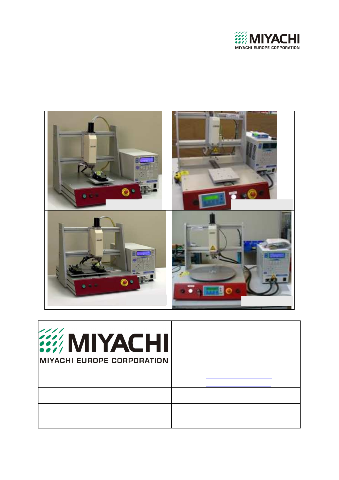
3.6 DT-350 SYSTEM DESCRIPTION..................................................................................18
3.7 DT-360 SYSTEM DESCRIPTION..................................................................................19
3.8 DT-370 SYSTEM DESCRIPTION..................................................................................20
3.9 DT-450 SYSTEM DESCRIPTION..................................................................................21
4 INSTALLATION....................................................................................................................22
4.1 TRANSPORTATION.......................................................................................................22
4.2 INSTALLATION.............................................................................................................22
4.3 POST INSTALLATION ADJUSTMENT INSTRUCTIONS ............................................26
4.3.1 DT-350 and 260 systems.........................................................................................26
4.3.2 DT-370 systems.......................................................................................................30
4.3.3 DT-450 systems.......................................................................................................32
5 THE CONTROL PANELS.....................................................................................................37
5.1 MAIN CONTROL PANEL..............................................................................................37
5.2 MAIN CONTROL PANEL (TD200 HEAT CONTROL).................................................38
5.3 CONSTANT HEAT CONTROL PANEL.........................................................................38
5.4 UNIFLOW CONTROL PANEL......................................................................................39
5.5 TD200 CONTROL PANEL.............................................................................................39
5.5.1 TD200 keys..............................................................................................................39
5.5.2 TD200 screens DT-350, DT-360, DT-370 ..............................................................40
5.5.3 Failure messages DT-350, DT-360, DT-370 ..........................................................44
5.5.4 TD200 screens DT-450 (General)...........................................................................46

5 D
ESK
T
OP
S
ERIES
–
AUTOMATIC OPERATION
5.5.5 TD200 screens DT-450 (Options)...........................................................................49
6 GENERAL OPERATION OF THE DESKTOP SYSTEM......................................................54
7 MAINTENANCE AND REPAIR............................................................................................54
7.1 ADJUSTMENTS.............................................................................................................54
7.2 PREVENTIVE MAINTENANCE....................................................................................54
7.3 TECHNICAL MAINTENANCE......................................................................................58
7.3.1 Fuse checks .............................................................................................................58
8 CALL MIYACHI EUROPE CORPORATION .......................................................................59

6 D
ESK
T
OP
S
ERIES
–
AUTOMATIC OPERATION
1SAFETY PRECAUTIONS
1.1 GENERAL SAFETY PRECAUTIONS
WARNING:
Read this manual carefully before doing work on the Desktop
system. Your supplier has no liability for injuries, damage and/or
excessive wear, due to incorrect maintenance, unintended use,
modifications and deactivation of safety devices.
WARNING:
The Desktop system and its safety devices must not be modified or
changed without written permission from your supplier.
WARNING:
It is forbidden to install the Desktop system in an area with a
possible explosive hazard due to chemicals or gases.
NOTE:
If the Desktop system is being used by a third party, you, as the
owner/user, are responsible unless it is agreed otherwise.
WARNING:
Repair or maintenance of electrical circuit or component must only
be done by qualified and trained personnel. Covers must only be
removed and installed by a qualified technician.
NOTE:
Figures in this manual may not be exactly as shown.
1.2 WARNINGS ON THE DESKTOP SYSTEM:
To warn the user/owner of the Desktop system for certain dangers/risks several warning
pictograms have been mounted on the Desktop system.

7 D
ESK
T
OP
S
ERIES
–
AUTOMATIC OPERATION
Table 1: Pictograms on the Desktop system
Warning: There is a risk of direct or indirect contact to live parts.
Access is only allowed for technically qualified personnel.
Labels are placed on the outside and the inside of the system and on
connection boxes near to live parts.
Warning: Risk of getting crushed between moving parts.
Labels are placed near moving parts.
Hot surface:
Burning risk at the thermode and machine covers.
Make sure that the machine has cooled sufficiently before you carry out
maintenance work.
General safety symbol
Ensure the machine is only switched on when all the guards are in place.
Keep the machine work table free of obstacles.
Earth (Ground) point
The label is placed on the left side of the system..
Warning: There is a risk of direct or indirect contact with live parts when
covers are open.
Labels are placed on the outside of the control cabinet.
Warning for maintenance and repair to make sure the main switch on the
rear of the system cannot be switched on unintentionally.
Recycling note: All parts of the Desktop system must be removed for
recycling in accordance with local regulations, preferably to a company that
can enable reuse of the materials.
NOTE:
Regularly check if all pictograms are still in place on the unit.
If they are not, replace them as quickly as possible.

8 D
ESK
T
OP
S
ERIES
–
AUTOMATIC OPERATION
2INTRODUCTION
2.1 GENERAL
This user manual makes sure new users are familiar with the operating and maintenance
procedures, while experienced users may use this document as a reference work. References
to other documents are made when necessary.
Operators and technicians using the machine for the first time should study this manual
carefully, in particular the safety instructions given in section 1.
Additional training by Miyachi Europe Corporation is recommended if the user wants to
become quickly familiar with the system. The training course consists of, among other things,
training in the completely independent operation of the system. Knowledge transfer should
not only take place by circulating this manual among the operators, but by practising with the
equipment and doing practical work with the machine.
The manual is based on current techniques. Miyachi Europe Corporation retains the right to
make changes to the documentation without being obliged to alter all previous versions.
Keep this instruction manual carefully for future use.
To underline certain subjects or actions the following markings are used in the text.
Tip
Suggestions and advice for carrying out certain tasks more easily.
NOTE:
The statement concerned is to draw the user's attention to possible
problems.
WARNING:
If the procedure is not performed carefully the users can injure
themselves or others or seriously damage the system.
NOTE:
Figures in this manual may not be exactly as shown.

9 D
ESK
T
OP
S
ERIES
–
AUTOMATIC OPERATION
Also pay special attention to the following:
Ensure a clean working environment with adequate illumination
Keep the control cabinets closed during normal use
Only use original components supplied by Miyachi Europe Corporation
The Desktop system is built for simple and efficient operation. However you must take note
of the contents of this manual and act accordingly. All personnel who work on or in the
vicinity of the installation must be aware of these instructions.
In addition to the instructions in this manual, all current general safety regulations and
conditions must be obeyed.
Competent persons are persons who:
- have a certain level of knowledge gained by training/education
- have certain skills necessary to operate the Desktop system.
The operator has to be a competent person.
Qualified technicians are persons who:
- are competent
- have a certain level of technical knowledge gained by training/education
- are familiar with the techniques used in the unit
- are aware of the possible risks (trained Miyachi Europe Corporation personnel).
WARNING:
The installation, technical maintenance, repair and removal and
removal of components may only be done by qualified technicians,
unless specified otherwise.
Desktop system operators are competent persons responsible for controlling the machine,
cleaning the unit and simple maintenance operations.
Desktop system qualified technicians are responsible for the installation, setting up and other
maintenance operations.
The purpose of this user manual is to create a safe and an efficient interaction between man
and system.
2.2 INTENDED USE
The Desktop is a system for the manual loading and unloading of the parts that are then
processed under fully automatic control.
The system can be used for Hot-Bar Reflow soldering, Heat-Seal Bonding, ACF laminating
and ACF Bonding.
The system has been developed for joining various product components.
The correct operating conditions are described in this user manual.

10 D
ESK
T
OP
S
ERIES
–
AUTOMATIC OPERATION
WARNING:
Your supplier has no liability for injuries, damage and/or excessive
wear, due to incorrect maintenance, unintended use, modifications
and deactivation of safety devices.
2.3 PRINCIPLE OF OPERATION
The system is a Desk-top system and is built on a chassis with integrated controls.
The machine operator is responsible for the manual positioning of the product components.
The alignment of the product components is done in a fixture, using a micrometer screw, one
or more dowel pins and/or an optional camera-monitor system.
After the product components are positioned, the system is operated by the start button or
buttons. The joining cycle will then be carried out. When the joining cycle is completed, the
product must be removed from the system by an operator.
The principle of the bonding system is the bonding of products by controlled movements of a
thermode, thus creating a known force, at a preset temperature and time.
The joining cycle is as follows:
The thermode moves down in the Z-axis under pneumatic or motorised control. It is then
heated until the preset temperature has been reached. The joining operation is carried out at a
constant thermode temperature. The thermode will then move up and the system is ready for
the next joining cycle.
2.4 SOUND LEVEL
The sound level has been measured in accordance with the Machine Directive requirements.
The A-weighted equivalent continuous sound pressure has been measured at the working
place during normal operating conditions. The sound level has been measured at a distance of
one metre from the machine and at a height of 1.60 m above the reference plane. The
measured A-weighted equivalent continuous sound pressure level (L
Aeq
) does not exceed 70
dB(A).
2.5 SYSTEM REQUIREMENTS
The equipment requires no special foundation. A level table or bench strong enough to
support the system is sufficient. When used in production, the machine and the adjacent area
must be well illuminated.

11 D
ESK
T
OP
S
ERIES
–
AUTOMATIC OPERATION
2.6 SPECIFICATIONS – AIR AND ELECTRICAL SUPPLIES
General
Weight Joining system 40 kg / 88 lbs
Dimensions Joining system
Depth
Width
Height
System: Heat Source:
600 mm / 23.62 Inch Dependent on
550 mm / 21.65 Inch Unflow constant heat
510 mm / 20.04 Inch
Maximum fixture height 80 mm / 3.15 Inch
Gantry open width 520 mm / 20.47 Inch
Fixture assembly base plate 160x160 mm / 6.30x6.30 Inch
Starting operation Two hand control
Operating temperature 15-40 °C / 60-104 °F
Operating humidity 93%@40 °C / 93%@104 °F
Connection requirements
Input voltage Uniflow
Main fuse
Input voltage Desktop (See note below)
Main fuse
230 Vac, 50 Hz, 1-Phase / earth / zero
16 A max, type C or D delay fuse
230 Vac, 50 Hz, 1-Phase / earth / zero (Europe)
4 A max, type C or D delay fuse
Compressed air required 6 bar, dry & filtered air
Machine data
Maximum peak current (Uniflow)
Peak power (Uniflow 2)
Maximum peak current (Desktop)
Peak power (Destktop)
Control voltage, internal
16 A
3.5 kw
4 A
300 W
12 Vdc, supplied by the transformer (option)
24 Vdc, supplied by the transformer (option)
Optional
Customer’s choice
Note: Electrical supplies in non-European countries will be different.

12 D
ESK
T
OP
S
ERIES
–
AUTOMATIC OPERATION
3CONSTRUCTION
3.1 GENERAL CONSTRUCTION
The Desk Top (DT) systems consist of several parts, the main ones of which are shown
below.
A. Left/right and rotation head adjustment plate
B. Power cable connection block
C. Electrical control drawer
D. Wrist strap earth (grounding) point
E. Portal (front/rear adjustment of the bond head)
A
D
B
C
E

13 D
ESK
T
OP
S
ERIES
–
AUTOMATIC OPERATION
A. Pneumatic head (80N or 500N)
B. Uniflow power source
C. Safety cover power cables (option)
D. Control panel
E. Base plate
F. Quick Connect Block (QCB) and Thermode
Note: For more details about the pneumatic bonding head, refer to manuals 69H0082 (80N) or
69H0504 (500N).
A constant heat control panel is shown at a
typical position (A). It may be installed in
other positions.
A
B
C
D
E
F
A

14 D
ESK
T
OP
S
ERIES
–
AUTOMATIC OPERATION
Rear panel (pulsed heat)
A. Power input and data cables from the Uniflow
B. Power input and main switch
C. Data plate and CE conformation
D. Pneumatic input connection
Note: The illustration above may not be exactly as shown.
Rear connection panel (TD200 heat control)
A. Earth (ground) connection
B. Power input and data cables from the Uniflow
C. Mains switch
D.Data plate and CE conformation
E. Pneumatic and electrical control cables
F. Pneumatic input connection
G.Mains input connector
Note: The illustration above may not be exactly as shown.
A B C D
A
B
C
G
D
F
E

15 D
ESK
T
OP
S
ERIES
–
AUTOMATIC OPERATION
Rear view modified DT-450 with options
A. Foot firing switch (option)
B. J4B firing home switch/in position sensors/start switches
C. J4A control functions (miscellaneous)
A
B C
D
E
F
G
H
J

16 D
ESK
T
OP
S
ERIES
–
AUTOMATIC OPERATION
D. Fan outlet
E. Main switch
F. Mains input connection
G. Serial number and CE plate
H. J6B Z-axis valve/cool valve
J. J6A relays
Note: The connections may not be the same as shown.
3.2 TAPE INTERPOSER MODULE
If this is installed, refer to the applicable manual.
3.3 ACF MODULE
If this is installed, refer to the applicable manual.
3.4 SAFETY MEASURES AND DEVICES
For a list of the system pictograms, refer to table 1 of this manual. Make sure you obey the
warning and caution instructions in this table.
3.4.1 Protection guards
The two-hand control is designed in such a way that the operator is protected from crushing
and burning. It also prevents the unintended starting of the bonding process. When the head is
moving down or the turntable is moving, there is a danger of crush injuries.
3.4.2 Hot parts
If the thermode is touched there is a danger of burn injuries as the temperature of the
thermode can rise to 600 deg C. The thermode area has an optional shield and a warning
pictogram is placed on the head guard.
3.4.3 Electrical safety
The Desktop system using pulsed heat is not provided with a main switch. The system power
is controlled by the Uniflow. The Desktop system using constant heat control has no mains
switch and before work is done, the complete desktop must be disconnected from the main
supplies.
3.4.4 Emergency stop
The Desktop system is equipped with one emergency stop push button which is mounted on
the front of the machine. Activation of the emergency stop button will stop all machine
movements, but if the bond head is in the down position it well rise. Additionally, the main
supply must be disconnected to isolate the constant heat controller.
13

17 D
ESK
T
OP
S
ERIES
–
AUTOMATIC OPERATION
CAUTION
If you push the red button when the head is in the down position, it
will move up.
Power supply and compressed air will be removed from certain parts of the machine
immediately.
NOTE:
Push the red button to activate the emergency stop.
Deactivate the emergency stop by turning it counter clockwise.
3.5 CERTIFICATION
The Desktop system and this manual have been designed, constructed and tested according to
the European directives. During all these phases the relevant European standards have been
taken into account. The CE-mark has been mounted on the unit. The directives and the
standards mentioned are enumerated in the EC-Declaration of Conformity.

18 D
ESK
T
OP
S
ERIES
–
AUTOMATIC OPERATION
3.6 DT-350 SYSTEM DESCRIPTION
The illustrations above show a system with pulsed heat. PLC and constant heat systems are
shown later.
The DT-350 is a Uni-slide system where the parts are positioned on a fixture that can be
moved pneumatically through front and rear locked positions. It is supplied with an anodised
aluminium base plate that has a pattern of holes drilled and tapped into it. This hole pattern
accepts a Miyachi fixture base plate, which is customer dependent and is mounted with bolts
and dowel pins.
The front position is used for loading, positioning and subsequent unloading after processing
and the rear position for the bonding process.
Operation of the two hand controls moves the slide between the front and rear positions.
When the correct position is reached, the slide automatically locks into place.
For safety reasons, a sensor checks if the slide is in the correct position for the bonding
process. Only then can the process cycle can be started with the two hand control.

19 D
ESK
T
OP
S
ERIES
–
AUTOMATIC OPERATION
3.7 DT-360 SYSTEM DESCRIPTION
The illustrations above show a system with pulsed heat. PLC and constant heat systems are
shown later.
The DT-360 is a Uni-slide system where the parts are positioned on a fixture that can be
moved pneumatically through a front and two rear locked positions. It is supplied with an
anodised aluminium base plate that has a pattern of holes drilled and tapped into it. This hole
pattern accepts a Miyachi fixture base plate, which is customer dependent and is mounted
with bolts and dowel pins.
The front position is used for loading, positioning and subsequent unloading after processing
and the two rear positions for two separate bonding processes.
Operation of the two hand controls moves the slide between the front and first rear positions.
When the bonding process at the first position is completed, the slide moves automatically to
the second rear position. Again, when the correct position is reached, the slide automatically
locks into place.
For safety reasons, two separate sensors check if the slide is in the correct position for the
bonding processes. Only then can the process cycle can be started with the two hand control.

20 D
ESK
T
OP
S
ERIES
–
AUTOMATIC OPERATION
3.8 DT-370 SYSTEM DESCRIPTION
The DT-370 is a Uni-Slide systems with a left-right slide. It is supplied with an anodised
aluminium base plate that has a pattern of holes drilled and tapped into it. This hole pattern
accepts a Miyachi fixture base plate, which is customer dependent and is mounted with bolts
and dowel pins.
The left-right slide makes it possible to load, position and unload parts in one position while
the bonding process takes place in the other position. This increases the output of the slide
system.
The parts are loaded with the fixture in the left or right positions. When the slide is
pneumatically moved to each position it automatically locks into place. The next set of parts
can be loaded while processing takes place on the other.
Operation of the two hand controls moves the slide between the left and right . When the
bonding process at the first position is completed, operation of the two hand controls moves
the slide to the second position. Again, when the correct position is reached, the slide
automatically locks into place.
For safety reasons, a sensor checks if the slide is in the correct position for the bonding
process. Only then can the process cycle be started with the two hand control. Two separate
sensors are mounted and with these, independent process settings for both bonding positions
can be automatically recalled.
This manual suits for next models
3
Table of contents
Other Miyachi Welding System manuals
Popular Welding System manuals by other brands

Northern Industrial
Northern Industrial ARC 200 Operator's manual

HG
HG Soldatech TL200PHG user manual

Kühtreiber
Kühtreiber MAKin 160 MMA user manual

Hypertherm
Hypertherm powermax65 Field Service Bulletin

Castolin
Castolin 2000 FLEX Instructions for use and maintenance

ESAB
ESAB Aristo RoboFeed 3004w Service manual