manuals.online logo
Brands
  1. Home
  2. •
  3. Brands
  4. •
  5. LOTOS
  6. •
  7. Welding System
  8. •
  9. LOTOS MIG250i User manual

LOTOS MIG250i User manual

LLLOOOTTTOOOSSS MMMIIIGGG222555000iii
MMMIIIGGG WWWeeellldddeeerrr
INSTRUCTION MANUAL·M I G 250 1
CCC OOO NNN T T T EEE NNN TT T SSS
- Safety…………………………..………………..…………………………….…..……....……….. 2
-General Description……...……….......……...…………………….………...……….....………. 3
-M a i n Parameter…….……...…. .........…….....………………………………….…..……….….. 4
-Installation& Operation……………………………………………………………………………. 5
-Speed-r e a d Table…………….….……….......………...…..……….……………………....….… 8
-Caution..……..………..…... .........…. ..................……………………….………..………….… 10
-Maintenance....................…………………………………………...………………. .....…......... 10
-Daily Checking………….…………………………………………………….….……....….…….. 11
Hereby westate t h a t weprovide oneyear ofguarantee f o r t h i s welding equipment since
t h e dateofpurchase.
P l e a s e read a n d understand t h i s instruction manual carefully before t h e installation a n d
operation oft h i s equipment.
T h e contents oft h i s manual m a y berevised without prior notice.
Please visit us http://www.uwelding.com.au/ for more information.
i
INSTRUCTION MANUAL·M I G 250 2
SSS AAA FF F EEE TT T YYY
Welding andcutting is dangerous t o t h e operator, people in o r near t h e working area, andt h e
surrounding, if t h e machine is notcorrectly operated. Therefore, t h e performance o f welding/cutting
m u s t onlybeunder t h e strict andcomprehensive observance ofa l l relevant safety regulations.
P l e a s e read a n d understand t h i s instruction manual carefully before t h e installation a n d operation.
·T h e switching offunction modes is possibly damaging t o t h e
machine, while t h e welding operation isperformed.
·Do disconnect t h e electrode-holder cable witht h e machine,
before t h e performance o f welding.
·Asafety switch is necessary t o prevent t h e machine f r o m
electric-leakage.
·Welding t o o l s should beofh i g h quality.
·Operators should bequalified.
EEE l l l eee ccc t t t r r r i i i ccc sss hhh ooo ccc kkk : : : III ttt ccc aaa nnn kkk iii lll lll ...
·Connect t h e earthcable according t o standard regulation.
·A v o i d a l l contact withlive electrical partsoft h e welding circuit,
electrodes andwireswithbare hands. I t is necessary f o r t h e
operator t o wear d r y welding gloves while heperforms t h e
welding task.
·T h e operator should keep t h e working p i e c e insulating f r o m
himself/herself.
SSS mmm ooo kkk eee aa a nnn ddd ggg aaa sss ggg eee nnn eee r r r aaa t t t eee ddd wwwhhhiiillleee www ee e l l l ddd i i i nnn ggg ooorrr ccc uuu t t t t t t i i i nnn ggg : : : hhh aa a r r r mmm f f f uuu l l l
tttoooppp eee ooo ppp l l l ee e ’ ’ ’ ss s hhh eee aa a l l l t t t hhh . . .
·A v o i d breathing t h e smoke andgasgenerated while welding o r
cutting.
·K e e p t h e working area ingood ventilation.
AAArrrcccr r r aaa yyy sss : : : hhh aa a r r r mmm f f f uuu l l l tttoooppp ee e ooo ppp l l l ee e ’ ’ ’ sss eee yyy eee sss aa a nnn ddd sss kkk i i i nnn . . .
·Wear welding helmet, anti-radiation glassa n d workclothes
while t h e welding operation isperformed.
·Measures a l s o should bet a k e n t o protect people ino r near t h e
working area.
.
FFFiiirrreee hhh aaa z z z aa a r r r ddd
·T h e welding splash m a y cause f i r e , t h u s remove flammable
material away f r o m t h e working place.
·Have af i r e extinguisher nearby, andhaveatrained person
ready t o useit.
NNN ooo i i i sss eee : : : ppp ooo ss s ss s i i i bbb l l l yyy hhh aa a r r r mmm f f f uuu l l l tttoooppp ee e ooo ppp l l l ee e ss s ’ ’ ’ hhh eee aa a r r r i i i nnn ggg . . .
·Noise is generated while welding/cutting, wear approved ear
protection ifnoiselevel ishigh.
MMM aaa ccc hhh i i i nnn eee fff aaa uuu ll l ttt :::
·Consult t h i s instruction manual.
·Contact your local dealer o r supplier f o r further advice.
i
INSTRUCTION MANUAL·MIG 250 3
GGG EEE NNN EEE RRR AAA LL L DDD EE E SS S CCC RRR I I I PP P TT T I I I OOO NNN
This welding machine is manufactured with advanced inverter technology. With high-power
component IGBT and PWM technology, the inverter convert the DC voltage, which is rectified from
input 50Hz/60Hz AC voltage, to high-frequency 20KHz AC voltage; as aconsequence, the voltage
is transformed and rectified. The features of this product are as follows:
-IGBT inverter technology, current control, high quality, stable performance;
-Closed feedback circuit, invariable voltage output, great ability of balance voltage up to ±15%;
-Electron reactor control, stable welding, little splash, deep melting, excellent welding seam
reshaping;
-Slow weld wire feeding for arc starting, be able to cut small ball after welding ,successful arc
starting;
-Suit for welding medium thin plate more than 0.8mm;
-Small-sized, light-weighed, easy to operate, economical, practical.
TTT hhh ee e eee f f f f f f i i i ccc i i i eee nnn ccc yyy ooofff ttthhhiiisss mmm aaa ccc hhh i i i nnn eee ccc aaa nnn r r r eee aaa ccc hhh uuu ppp tttooo 888 555 %%% , , , aa a nnn ddd sss aaa vvv eee eee nnn eee r r r ggg yyy bbbyyy 333 000 %%% ccc ooo mmm ppp aaa r r r eee ddd wwwiiittthhh
ttthhheee t t t r r r aa a ddd i i i t t t i i i ooo nnn aa a l l l mmm aaa ccc hhh i i i nnn eee . . .
BBB l l l ooo ccc kkk DDD i i i aaa ggg r r r aaa mmm
i
INSTRUCTION MANUAL·4
CCCiii rrr ccc uuu iii ttt dddi i i aaa ggg r r r aaa mmm
TTTYYY PPP EEE MMMIIIGGG222 555 000 iii
Input Voltage (VAC) 1phase 240V±15%
Input current (A) 14
Power capacitance (KVA)) 9.2
Output current range (A) 50-250
Output voltage (VDC) 15-29
Duty cycle 60%
Power factor 0.85
Efficiency 85%
Type of wire feeder Embedded
Post-flow time (s) 1
Diameter of the coil (mm) 270
Diameter of the wire (mm) 0.8/1.0
Size of the machine (mm) 500×270×440
Weight (Kg) 26
Thickness (mm) ≥0.8
Insulation class F
Protection class IP21

MAIN SWITCH
PPPRRROOOEEECCCTTT
CCCIIIRRRCCCUUUIIITTT
PPPOOOWWWEEERRR
SSSUUUPPPPPPLLLYYY CONTROL
CCCIIIRRRCCCUUUIIITTT WWWIIIRRREEE
FFFEEEEEEDDDEEERRR
NNNOOOTTTEEE:::
TTTHHHEEE IIINNNPPPUUUTTT VVVOOOLLLTTTAAAGGGEEE IIISSS 111 PPPHHHAAASSSEEE 222444000 VVVAAACCC NAME
TYPE
CIRCUIT DIAGRAM
MIG 250i
MMM AAA I I I NNN PPP AAA RRR AAA MMM EE E TT T EEE RRR
MIG 250 i
INSTRUCTION MANUAL·5
I I I NNN SSS TTT AAA LLL LLL TTT I I I OOO NNN &&& OOO PPP EEE RRR AAA T T T I I I OOO NNN
111...CCC ooo nnn nnn ee e cc c t t t i i i ooo nnn ooofff ttthhheeei i i nnn ppp uuu t t t ccc aaa bbb l l l eee
- A primary power supply cable is available f o r t h i s welding equipment. Connect t h e power supply
cable withrequired voltage. MIG250i isof1-phase 240VAC.
-Theprimary wireshould b e connected t o t h e corresponding socket t o avoid oxidization.
-Usemulti-meter t o see whether t h e voltage value varies int h e givenrange0.
222...CCC ooo nnn nnn ee e cc c t t t i i i ooo nnn ooofff ooo uuu t t t ppp uuu t t t ccc aaa bbb l l l eee (according t o t h e following drawing)
2a.P l u g t h e f a s t connector, t o t h e “
”
ont h e panel board, andtighten itclockwise, while t h e
earthclamp a t t h e other endisconnected t o t h e workpiece.
For convenient welding operation, t h e cross section area o f welding cable should be35mm
2,
50mm
2
,70mm
2in case oft h e maximum applicable current 170A, 250A, 450A. T h e increase of
t h e cross section area o f welding cable is necessary according t o t h e current density. T h e
recommended ratioofamperage a n d cross section area ofleadis5A/m m 2
.
2b.Connect t h e f a s t connector oft h e t o r c h t o t h e “ ” o f ont h e panel board, andtighten it
clockwise.
333...III nnn sss ttt aaa lll lll aaa ttt iii ooo nnn ooofff w w w i i i r r r e e e f f f eee eee ddd eee r r r
P l e a s e refert o following drawing f o r t h e cables’ connection. Install t h e wirefeeder.
-Fixt h e wirereel t o t h e racka x i s ont h e wirefeeder; m a k e sure t h e holeoft h e wirereel matches
wellwitht h e boltont h e racka x i s .
-The wireshould beunpacked in clockwise direction, andcut offt h e curved part,whicha r e t i e d
around t h e f i x e d hole.
-Unite t h e screw o n t h e wire-pressing wheel, andm a k e t h e wireinto t h e gloveoft h e wirefeed
wheel, press t h e wiretightly, butnott o o tight, andt h e n thread t h e wireintot h e torch.
-Different wiret o different gloves according t o t h e i r diameter. Please refert o page 8Speed-read
table.
-Press the” wirefeeding” button t o feed t h e wireoutoft h e welding gun.







 
MIG 250 i
INSTRUCTION MANUAL·6
444... PPP aaa nnn eee l l l ddd eee ss s cc c r r r i i i ppp t t t i i i ooo nnn ( ( ( sss eee eee ttthhheee f f f ooo l l l l l l ooo www i i i nnn ggg ddd r r r aa a www i i i nnn ggg ) ) )
1)
CCC ooo nnn nnn eee cc c t t t i i i ooo nnn ooofff SSS hhh i i i eee l l l ddd i i i nnn ggg GGGaaasss
Connect the CO2tube, which come from the wire-feeder
to the copper nozzle of gas bottle. The gas supply
system includes the gas bottle, the air regulator and the
gas hose, the heater cable which plug should be insert
into the socket of machine’s back, and use the hose
clamp to Tighten it to prevent leaking or air-in, so that
the welding point is protected.
Please note:
1) Leakage of shielding gas affects the performance
of arc welding.
2) Avoid the sun shining on the gas cylinder to
eliminate the possible explosion of gas cylinder
due to the increasing pressure of gas resulted by
heating of sun shining.
3) It is extremely forbid to knock at gas cylinder and
lay the cylinder horizontally.
4) Ensure no person is up against the regulator,
before the gas release or shut the gas output.
5) The gas output volume meter should be installed
vertically to ensure the precisely measuring.
6) Before the installation of gas regulator, release
and shut the gas for several time in order to
remove the possible dust on the sieve to avail the
gas output.
MIG 250 i
INSTRUCTION MANUAL·7
OOO PP P EE E RRR AAA T T T I I I OOO NNN
- - - OOO ppp ee e r r r aaa t t t i i i ooo nnn sss t t t eee ppp sss
-Turn on the air switch of the welding machine, open the gas cylinder valve, and adjust the flow
meter to the desired position.
-Choose contact tip’s aperture of the welding gun according to the diameter of the welding wire.
-Adjust the voltage adjustment knob and current adjustment knob to the desired position according
to the thickness and craftwork of the work piece.
-Adjust the inductance adjustment knob to the desired position to get the right rigidity.
-Press the switch on the welding gun, then welding can be carried out.
--- SSS eee ttt ttthhheee www ee e l l l ddd i i i nnn ggg ccc uuu r r r r r r eee nnn t t t
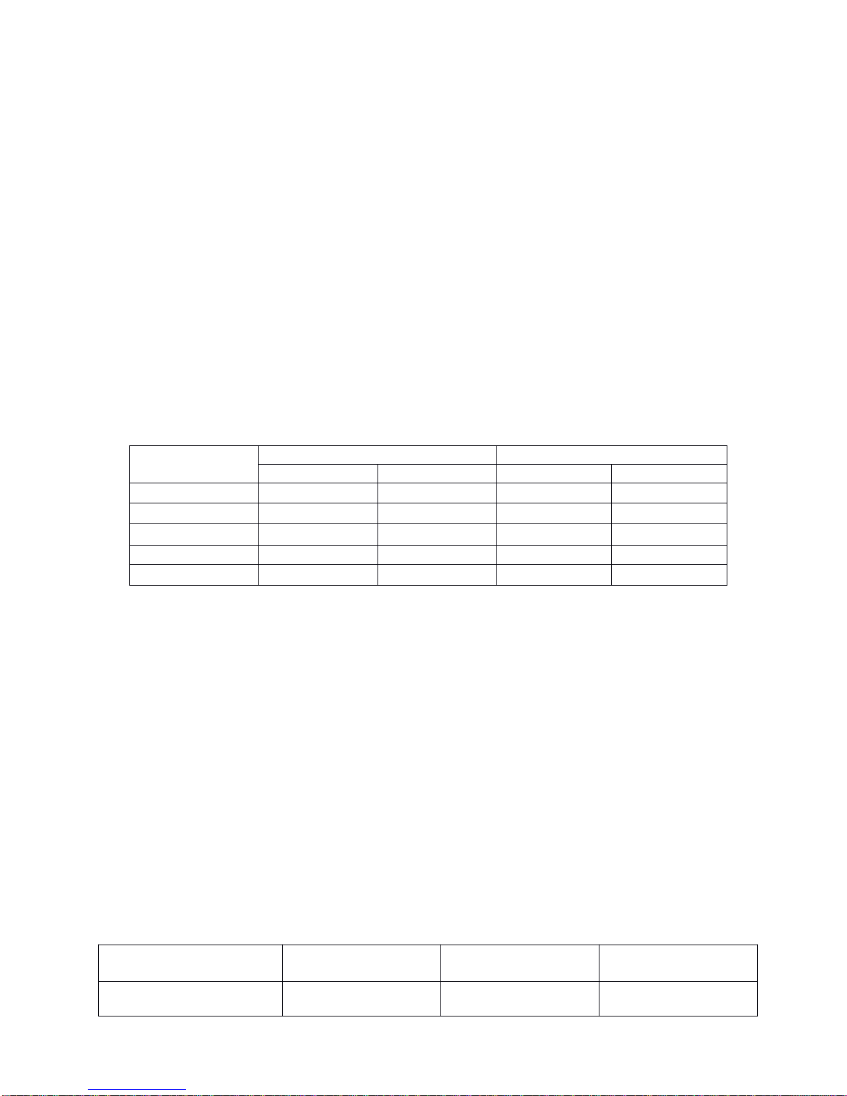
-The option of the welding current and welding voltage directly influences the welding stability,
welding quality and productivity. In order to obtain good weld, the welding current and welding
voltage should be set optimally. Generally, the setting of weld condition should be according to the
welding wire diameter, the melting form and the production requirement. Refer to the following
figure to set the welding current, while refer to the speed-read table on page 8to do the welding
operation according to different working condition.
Range of welding current and voltage in short circuit transition and granular transaction.
- - - TTT hhh ee e ooo ppp t t t i i i ooo nnn ooofff ttthhheee www ee e l l l ddd i i i nnn ggg sss ppp eee eee ddd
The welding quality and productivity should be taken into consideration for the option of welding
speed. In case that the welding speed increases, it weakens the protection efficiency and quickens
the cooling. As aconsequence, it is not optimal for the seaming. In the event that the speed is too
slow, the work piece will be easily damaged, and the seaming is not ideal. In practical operation, the
welding speed should not exceed 30m/h.
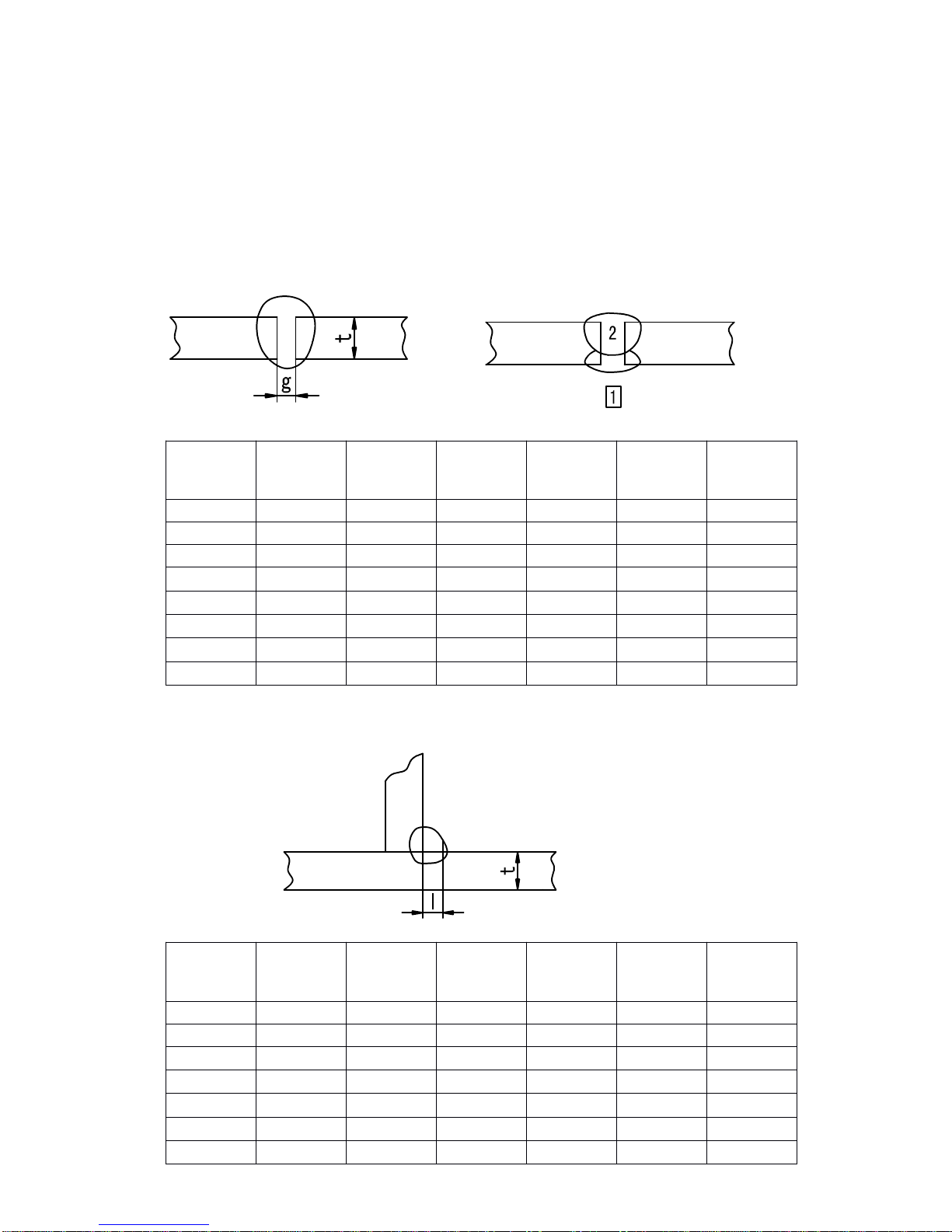
- - - TTT hhh eee l l l ee e nnn ggg t t t hhh ooofff wwwiiirrreee sss t t t r r r eee t t t ccc hhh i i i nnn ggg ooo uuu t t t
The length of wire stretching out the nozzle should be appropriate. The increase of the length of
wire stretching out of the nozzle can improve the productivity, but if it is too long, excessive spatter
presents in the welding process. Generally, the length of wire stretching out the nozzle should be 10
times as the welding wire diameter.
- - - TTT hhh ee e sss eee t t t t t t i i i nnn ggg ooofff ttthhheee CCC000222 ffflllooowww vvv ooo l l l uuu mmm eee
The protection efficiency is the primary consideration. Besides, inner-angle welding has better
protection efficiency than external-angel welding. For the main parameter, refer to the following
figure.
Option of C02flow volume
Wireφ(mm) Short circuit transition Granular transition
Current(A)Voltage (V) Current(A)Voltage (V)
0.6 40~70 17~19 160~400 25~38
0.8 60~100 18~19 200~500 26~40
1.0 80~120 18~21 200~600 27~40
1.2 100~150 19~23 300~700 28~42
1.6 140~200 20~24 500~800 32~44
Welding mode Thin wire C02
welding
Thick wire C02
welding
Thick wire, big
current C02welding
C02(L/min)5~15 15~25 25~50
MIG 250 i
INSTRUCTION MANUAL·8
SSS PPP EEE EEE DDD - - - RRR EEE AAA DDD TTT AAA BBB LLL EEE
T h e option oft h e welding current andwelding voltage directly influences t h e welding stability,
welding quality andproductivity. I n order t o obtain t h e good weld,t h e welding current andwelding
voltage should b e set optimally. Generally, t h e setting ofweldcondition should b e according t o t h e
welding diameter andt h e melting f o r m aswellast h e production requirement.
T h e following parameter isavailable f o r reference.
PPP aaa r r r aaa mmm eee t t t eee r r r fffooorrrbbb uuu t t t t t t - - - www ee e l l l ddd i i i nnn ggg ( ( ( PPP l l l eee aaa sss eee rrr eee ff f eee rrr tttooottthhheeef f f ooo l l l l l l ooo www i i i nnn ggg fff ii i ggg uuu rrr eee .. . )))
PPP aaa r r r aaa mmm eee t t t eee r r r fffooorrrfff ll l aaa ttt fff iii lll lll eee ttt www eee l l l ddd i i i nnn ggg ( ( ( PPP l l l eee aaa sss eee rrr eee ff f eee rrr tttooottthhheeef f f ooo l l l l l l ooo www i i i nnn ggg fff ii i ggg uuu rrr eee .. . )))
P l a t e
thickness
t(m m )
Gap
g(mm)
W i r e
φ(mm)
Welding
current
(A)
Welding
voltage
(V)
Welding
speed
(cm/min
)
Gas
volume
(L/min)
0.8 0 0.8~0.9 60~70 16~16.5 50~60 10
1.0 0 0.8~0.9 75~85 17~17.5 50~60 10~15
1.2 0 1.0 70~80 17~18 45~55 10
1.6 0 1.0 80~100 18~19 45~55 10~15
2.0 0~0.5 1.0 100~110 19~20 40~55 10~15
2.3 0.5~1.0 1.0 or 1.2 110~130 19~20 50~55 10~15
3.2 1.0~1.2 1.0 or 1.2 130~150 19~21 40~50 10~15
4.5 1.2~1.5 1.2 150~170 21~23 40~50 10~15
P l a t e
thickness
t(m m )
C o r n size
I(mm)
W i r e
φ(mm)
Welding
current
(A)
Welding
voltage
(V)
Welding
speed
(cm/min
)
Gas
volume
(L/min)
1.0 2.5~3.0 0.8~0.9 70~80 17~18 50~60 10~15
1.2 2.5~3.0 1.0 70~100 18~19 50~60 10~15
1.6 2.5~3.0 1.0 ~ 1.2 90~120 18~20 50~60 10~15
2.0 3.0~3.5 1.0 ~ 1.2 100~130 19~20 50~60 10~20
2.3 2.5~3.0 1.0 ~ 1.2 120~140 19~21 50~60 10~20
3.2 3.0~4.0 1.0 ~ 1.2 130~170 19~21 45~55 10~20
4.5 4.0~4.5 1.2 190~230 22~24 45~55 10~20
MIG 250 i
INSTRUCTION MANUAL·9
PPP aaa r r r aaa mmm eee t t t eee r r r fffooorrrfff iii lll lll eee ttt www ee e l l l ddd i i i nnn ggg iii nnn ttthhheeevvv eee r r r t t t i i i ccc aaa l l l ppp ooo ss s i i i t t t i i i ooo nnn ( ( ( PPP l l l eee aaa sss eee rrr eee ff f eee rrr tttooottthhheeef f f ooo l l l l l l ooo www i i i nnn ggg fff ii i ggg uuu rrr eee .. . )))
PPP aaa r r r aaa mmm eee t t t eee r r r fffooorrrLLL aa a ppp WWW ee e l l l ddd i i i nnn ggg ( ( ( PPP l l l eee aaa sss eee rrr eee fff eee rrr tttooottthhheeef f f ooo l l l l l l ooo www i i i nnn ggg fff iii ggg uuu rrr eee .. . )))
P l a t e
thickness
t(m m )
C o r n size
I(mm)
W i r e
φ(mm)
Welding
current
(A)
Welding
voltage
(V)
Welding
speed
(cm/min
)
Gas
volume
(L/min)
1.2 2.5~3.0 1.0 70~100 18~19 50~60 10~15
1.6 2.5~3.0 1.0 ~ 1.2 90~120 18~20 50~60 10~15
2.0 3.0~3.5 1.0 ~ 1.2 100~130 19~20 50~60 10~20
2.3 3.0~3.5 1.0 ~ 1.2 120~140 19~21 50~60 10~20
3.2 3.0~4.0 1.0 ~ 1.2 130~170 22~22 45~55 10~20
4.5 4.0~4.5 1.2 200~250 23~26 45~55 10~20
P l a t e
thickness
t(m m )
Welding
position
W i r e
φ(mm)
Welding
current
(A)
Welding
voltage
(V)
Welding
speed
(cm/min
)
Gas
volume
(L/min)
0.8 A 0.8~0.9 60~70 16~17 40~45 10~15
1.2 A 1.0 80~100 18~19 45~55 10~15
1.6 A 1.0 ~ 1.2 100~120 18~20 45~55 10~15
2.0
A
or B 1.0 ~ 1.2 100~130 18~20 45~55 15~20
2.3 B 1.0 ~ 1.2 120~140 19~21 45~50 15~20
3.2 B1.0 ~ 1.2 130~160 19~22 45~50 15~20
4.5 B 1.2 150~200 21~24 40~45 15~20
MIG 250 i
1 0
CCC AAA UUU TT T I I I OOO NNN
111... WWW ooo r r r kk k i i i nnn ggg ee e nnn vv v i i i r r r ooo nnn mmm ee e nnn t t t
1.1 T h e location i n which thiswelding equipment i s installed and operated should be of little dust, corrosive
chemical gas, flammable gas or materials etc, and of maximum 90% humidity;
1.2 A v o i d theoperation of welding i n theopen air unless theworking area sheltered f r o m thesun shining, rain
water and snow etc; thetemperature of working environment should be maintained within -10°Cto+40°C
;
1.3 T h e minimum distance of thiswelding equipment and wallshould be 30cm.
1.4 Keep theworking environment i n good ventilation.
222... SSS aaa f f f eee t t t yyy tttiiipppsss
Over-current/over-voltage/over-heating protection circuit i s installed i n thiswelding equipment. Iftheinput voltage
or theoutput current i s toohigh or over heating generated inside thiswelding equipment, thiswelding equipment
will stop automatically. However, excessive use (e.g. toohigh voltage) will still lead tomachine damage, so please
note:
2.1 Ventilation
H i g h current passes when welding i s carried out, thus natural ventilation cannot satisfy thewelding
equipment’s cooling requirement. Maintain good ventilation of thelouvers of thiswelding equipment. T h e
minimum distance between thiswelding equipment and any other objects i n or near theworking area
should be 30cm. Good ventilation i s of critical importance f o r thenormal performance and service l i f e of
thiswelding equipment.
2.2 Welding operation i s f o r b i d while thiswelding equipment i s of over-load.
Remember toobserve them a x load current at any moment (refer totheoptioned duty cycle). Makesure
that thewelding current should not exceed them a x load current. Over-load current could obviously
shorten thewelding equipment’s l i f e , or even burn theequipment.
2.3 Over-voltage i s forbid.
Regarding thepower supply voltage range of thewelding machine, please refer
t o
“Mainparameter
”
table.
T h i s welding equipment i s of automatic voltage compensation, whichenables themaintaining of the
voltage range within thegiven range. Incase that theinput voltage exceeds thestipulated value, i t would
possibly damage thecomponents of thewelding equipment.
2.4 A n earth terminal i s available f o r thiswelding equipment. Connect i t withtheearth cable toavoid thestatic
and electric shock.
2.5 Asudden halt m a y occur while thewelding operation i s carried out while thiswelding machine i s of over-
load status. Under thiscircumstance, i t i s unnecessary torestart thiswelding equipment. Keep thebuilt-in
f a n working tobring down thetemperature inside thewelding equipment.
MMM AAA I I I NNN TT T EEE NNN AAA NNN CCC EEE
1.Disconnect input plug o r power before maintenance
o r repair onmachine.
2.B e sure input ground wireis properly connect t o a
ground terminal.
3.Check whether t h e inner gas-electricity connection is
well(esp. t h e plugs), and tighten t h e loose
connection; if t h e r e is oxidization, remove it with
sand paper andt h e n re-connect.
4.K e e p hands, hair,loose clothing, andt o o l s away
f r o m live electrical partssuch asfans, wires.
5.Clear t h e d u s t atregular intervals withclean andd r y
compressed a i r ; if t h e working condition is with
heavy smoke anda i r pollution, t h e welding machine
should becleaned daily.
6.T h e compressed a i r should be reduced t o t h e
required pressure lest t h e little parts in t h e welding
machine bedamaged.
7.T o avoid waterandrain, if t h e r e is, d r y it in t i m e , and
check t h e insulation withmega-meter (including t h a t
between t h e connection andt h a t between t h e case
andt h e connection). O n l y when t h e r e isnoabnormal
phenomena can t h e welding continue.
8. I f t h e machine is notusedf o r along t i m e , putit into
t h e original packing ind r y condition.
INSTRUCTION MANUAL·MIG 250 i
11
DDD AAA I I I LL L YYY CCC HHH EEE CCC KKK I I I NNN GGG
T o m a k e best use of themachine, daily checking i s veryimportant. During thedaily checking, please check i n the
order of torch, wire-feeding vehicle, all kinds of PCB, thegas hole, and so on. Remove thedust or replace some
parts i f necessary. T o maintain thepurity of themachine, please use original welding parts.
CCC aaa uuu t t t i i i ooo nnn ss s :Onlythequalified technicians are authorized toundertake therepair and check taskof thiswelding
equipment i n case of machine f a u l t .
111... PPPooowwweeerrr sss ooo uuu r r r ccc eee sss
222... WWW eee l l l ddd i i i nnn ggg t t t ooo r r r cc c hhh
PPP aaa rrr ttt CCC hhh eee ccc kkk RRR eee mmm aaa r r r kkk sss
Control panel
1. Operation, replacement and installation of
S w i t c h .
2. S w i t c h on thepower, and check i f thepower
indicator i s on.
F a n 1. Check i f thef a n i s functioning and thesound
generated i s normal.
Ifthef a n doesn’t workor thesound i s
abnormal, do inner check.
Power supply
1. S w i t c h on the power supply, and check i f
abnormal vibration, heating of thecase of this
equipment, variation of colors of case or buzz
presents.
Other parts 1. Check i f gas connection i s available, case and
other joints are i n good connection.
PPP aaa rrr ttt CCC hhh eee ccc kkk RRR eee mmm aaa r r r kkk sss
Nozzle
1. Check i f thenozzle i s f i x e d firmly
and distortion of thetipexists. Possible gas leakage occurs due totheunfixed nozzle.
2. Check i f there i s spatter sticking
on thenozzle.
Spatter possibly leads tothedamage of torch. U s e anti-
spatter toeliminate thespatter.
Contact tip
1. Check i f thecontact tipi s f i x e d
firmly.
Unfixed contract tippossibly leads tothedamage of
torch.
2. Check i f the contact tip i s
physically complete.
T h e physically incomplete contact tippossibly leads to
theunstable arc and arc automatically terminating.
W i r e feeding
tube
1. Measure length of wire f e e d
tubestretching out.
T h e length of thewiref e e d tubstretching out should be
long enough tocontact thecontact tip.Replace i t i f l e s s
than 6mm, otherwise unstable arc
possibly
occurs.
2. Make sure that there i s the
agreement of wireand wiref e e d
tube.
Disagreement of thediameters of wireand wiref e e d
tube possibly leads totheunstable arc. Replace it/them
i f necessary.
3. Make sure that there i s no
bending or elongation of wire
f e e d tube.
Bending and elongation of wiref e e d tube possibly leads
to the unstable wire f e e d and arc. Replace i t i f
necessary.
4. Makesure that there i s no dust
or spatter accumulated inside
thewiref e e d tube, whichmakes
thewiref e e d tubblocked.
Ifthere i s dust or spatter, remove i t .
5. Check i f thewiref e e d tube and
O-shaped seal ring are
physically complete.
T h e Physically incomplete wiref e e d tube or O-shaped
seal ring possibly leads to the excessive spatter.
Replace thewiref e e d tube or O-shaped seal ring i f
necessary.
Diffuser
1.Make sure t h a t t h e diffuser
ofrequired specification is
installed andisunblocked.
Defection weldo r even t h e damage oft o r c h
occurs d u e t o t h e non-installation ofdiffuser o r
t h e unqualified diffuser.
INSTRUCTION MANUAL·MIG 250 i
1 2
333... WWWiiirrreeef f f eee eee ddd eee r r r
444... CCC aaa bbb l l l eee sss
PPP aaa rrr ttt CCC hhh eee ccc kkk RRR eee mmm aaa r r r kkk sss
Pressure
adjusting
handle
1.Check if t h e pressure-adjusting handle
is f i x e d a n d adjusted t o t h e desired
position.
T h e unfixed pressure-adjusting handle
leads t o t h e unstable welding output.
Wire-feeding
hose
1.Check if t h e r e is dusto r spatter inside
t h e hoseo r beside wire-feeding wheel. Removet h e dust.
2.Check if t h e r e is adiameter agreement
ofwirea n d wire-feeding hose.
Non-agreement oft h e diameter ofwire
andwire-feeding hosepossibly leads
t o t h e excessive spatter andunstable
a r c .
3.Check if rod andwirefeeding groove
a r e concentric. Unstable a r c possibly occurs.
Wire-feeding
wheel
1.Check if t h e r e is anagreement ofwire
diameter andwire-feeding wheel.
Non-agreement ofwirediameter and
wire-feeding wheel possibly leads t o
t h e excessive spatter andunstable a r c .
2.Checkift h e wiregroove isblocked. Replace itifnecessary.
Pressure
adjusting
wheel
1.Check if t h e pressure adjusting wheel
can rotate smoothly, andit’s physically
complete.
Unstable rotation o r physically
incompleteness oft h e wheel possibly
leads t o unstable wirefeeding anda r c .
PPP aaa rrr ttt CCC hhh eee ccc kkk RRR eee mmm aaa r r r kkk sss
T o r c h cable
1.Checkift h e cable oft o r c h istwisted. T h e twisted t o r c h cable leads t o
unstable wirefeeding anda r c .
2.Check if t h e coupling plug is in loose
connection.
Output cable
1. Check if t h e cable is physically
complete. Relevant measures should bet a k e n t o
obtain stable weldand prevent t h e
possible electric shock.
2. Check if insulation damage o r loose
connection exists.
Input cable
1.Check if t h e cable is physically
complete.
2.Check if insulation damage o r loose
connection exists.
E a r t h cable
1.Check if t h e earthcables a r e wellf i x e d
andnotshort-circuited. Relevant measures should bet a k e n t o
prevent t h e possible electric shock.
2.Check if t h i s welding equipment is well
grounded.
INSTRUCTION MANUAL·MIG 250 i

Other LOTOS Welding System manuals

LOTOS LT3500 User manual

LOTOS

LOTOS LT3500 User manual

LOTOS MIG140 User manual

LOTOS

LOTOS MIG140 User manual

LOTOS TIG140 User manual

LOTOS

LOTOS TIG140 User manual

LOTOS TIG200 User manual

LOTOS

LOTOS TIG200 User manual

LOTOS MIG140 User manual

LOTOS

LOTOS MIG140 User manual

LOTOS LTP5000D User manual

LOTOS

LOTOS LTP5000D User manual

LOTOS TIG200D User manual

LOTOS

LOTOS TIG200D User manual

LOTOS LTPDC2000D User manual

LOTOS

LOTOS LTPDC2000D User manual

LOTOS LTP5000D User manual

LOTOS

LOTOS LTP5000D User manual

LOTOS LTP6000 User manual

LOTOS

LOTOS LTP6000 User manual

LOTOS CT520D Specification sheet

LOTOS

LOTOS CT520D Specification sheet

LOTOS LT5000D User manual

LOTOS

LOTOS LT5000D User manual

LOTOS LT3200 User manual

LOTOS

LOTOS LT3200 User manual

LOTOS TIG200-DC User manual

LOTOS

LOTOS TIG200-DC User manual

LOTOS MIG175 User manual

LOTOS

LOTOS MIG175 User manual

LOTOS LTP7000 User manual

LOTOS

LOTOS LTP7000 User manual

Popular Welding System manuals by other brands

STAYER WELDING Gama PLASMA 40 COM GE operating instructions

STAYER WELDING

STAYER WELDING Gama PLASMA 40 COM GE operating instructions

GÜDE GIS 122 quick start guide

GÜDE

GÜDE GIS 122 quick start guide

iWeld HD 200 MULTICELL user manual

iWeld

iWeld HD 200 MULTICELL user manual

Magmaweld GL 451 user manual

Magmaweld

Magmaweld GL 451 user manual

Soyer BMS-8N operating instructions

Soyer

Soyer BMS-8N operating instructions

Draper MIG MWD100AT instructions

Draper

Draper MIG MWD100AT instructions

Huayuan Electric NB-500HK instruction manual

Huayuan Electric

Huayuan Electric NB-500HK instruction manual

Draper MW180AT instructions

Draper

Draper MW180AT instructions

A-Hand Technology PC508 manual

A-Hand Technology

A-Hand Technology PC508 manual

Weco Micro Pulse 302 MFK instruction manual

Weco

Weco Micro Pulse 302 MFK instruction manual

Silverline Arc Welder 55 - 160A Original instructions

Silverline

Silverline Arc Welder 55 - 160A Original instructions

Red-D-Arc FX360XL Operator's manual

Red-D-Arc

Red-D-Arc FX360XL Operator's manual

Miller Spectrum Lynx owner's manual

Miller

Miller Spectrum Lynx owner's manual

Campbell Hausfeld WS0970 Operating instructions and parts manual

Campbell Hausfeld

Campbell Hausfeld WS0970 Operating instructions and parts manual

Migatronic Automig 230 user guide

Migatronic

Migatronic Automig 230 user guide

Cebora Spot 2500 instruction manual

Cebora

Cebora Spot 2500 instruction manual

ESAB Warrior 400i CC/CV instruction manual

ESAB

ESAB Warrior 400i CC/CV instruction manual

Miller Gold Star 140 owner's manual

Miller

Miller Gold Star 140 owner's manual

manuals.online logo
manuals.online logoBrands
  • About & Mission
  • Contact us
  • Privacy Policy
  • Terms and Conditions

Copyright 2025 Manuals.Online. All Rights Reserved.