Chapter
2
Installing
.©
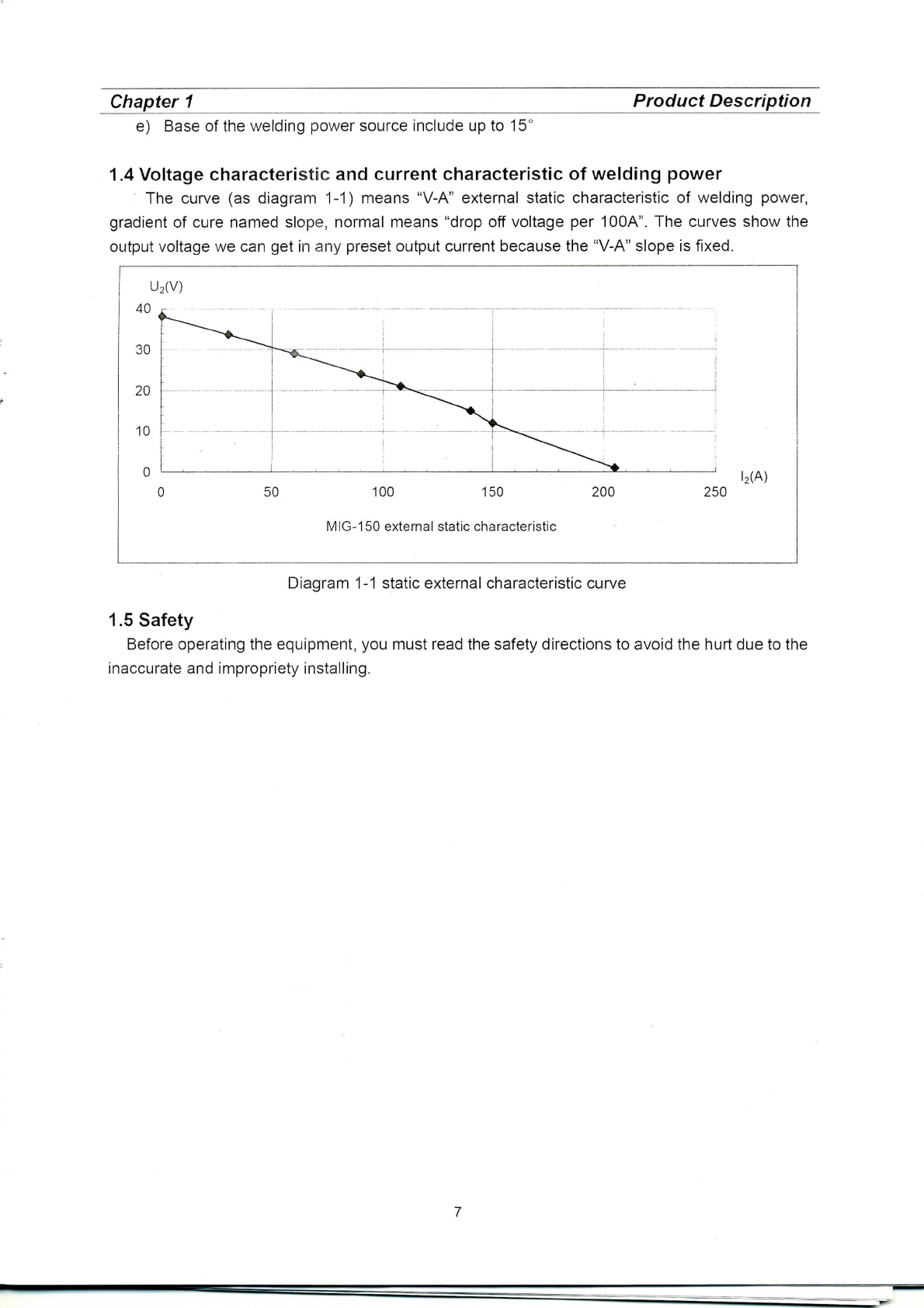
Diagram
2-2
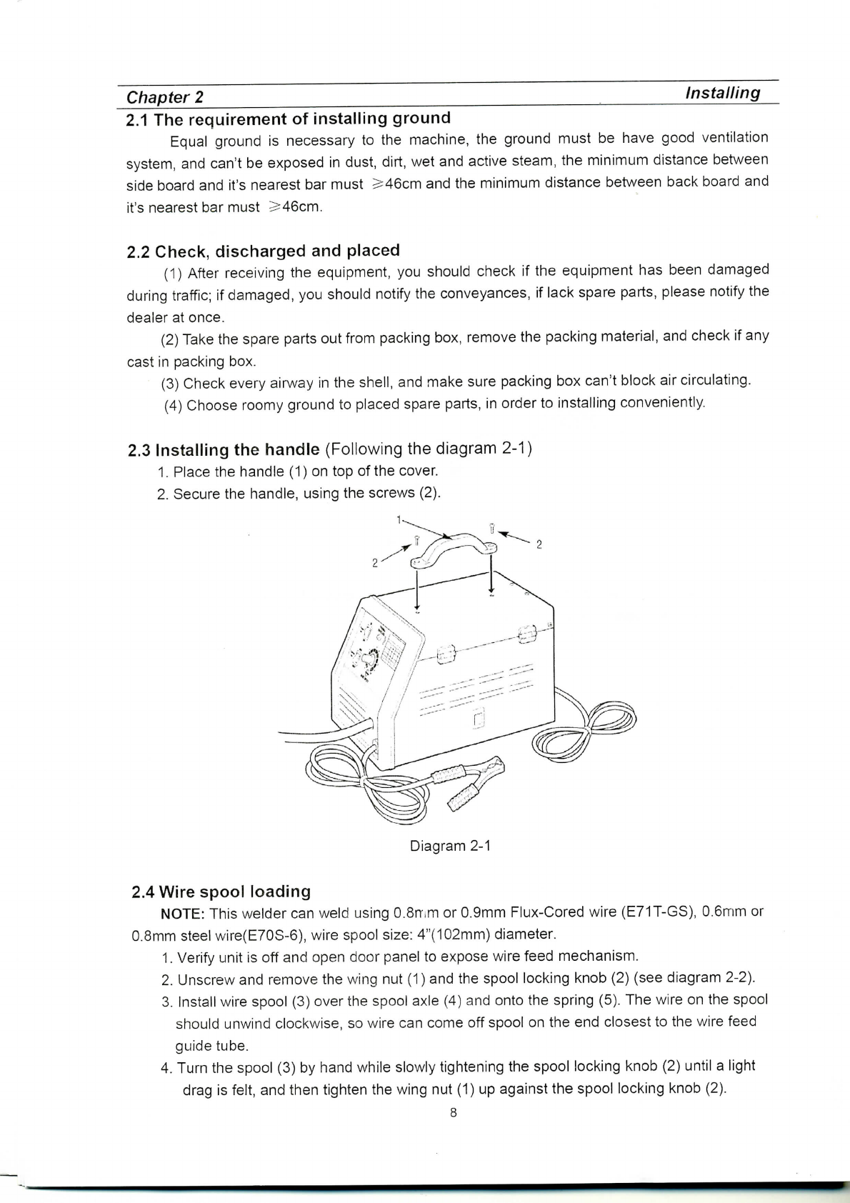
2.5
Wirethreading
1.
Loose
and
lower
the
tensionadjustingknob(7),rotate
the
swing
arm(8)
awayfrom
the
wire
feeddriveroll(9).
Diagram
2-3
2.
Carefullydetach
theendofthe
wirefrom
the
spool(3).
To
prevent
the
spoolfrom
unwinding,maintaintension
onthe
wireuntilafterstep
5.
3.
Cutthe
wire
end
fromspool
and
straighten
the
first
4"
(100mm).
Donot
allow
wire
to
unravel.
Makesure
thecutendhasno
burrs
or
sharpedges(cutagain,
if
needed).
4.
Thread
the
wire
through
wirefeedguidetube(6),over
the
groove
in
drive
roll
(9)and
into
torch
tube.
5.
Close
the
swing
arm(8)and
latch
the
tensionadjustingknob
(7)in
place.Makesure
the
wire
is
positioned
inthe
groove
ofthe
driveroll.
6.
The
milled
nut
(10)
onthe
tensionadjustingknob
(7)
adjusts
the
pressure
onthe
wire.
Adjust
pressure
by
turning
the
milled
nut
(10)
until
smooth
and
easywire
feeding.
Start
with
the
pressure
settoan
intermediatevalue.Readjust,
if
necessary.Slightlyless
pressure
mayberequired.
Ifthe
driverollslipswhilefeedingwire,
the
pressureshould
be
increased
until
the
wirefeedsproperly.
7.
Removenozzle
(11)
by
turningclockwise,thenunscrewcontact
tip
(12)
from
endof
welding
torch(Seediagram2-4).Plugwelderinto
a
properpower supplyreceptacle.
8.
Turn
on
welder
andset
wirespeedrate
to6.Laythe
torchcable
outina
straightline
and
presstorchtriggeruntilwirefeeds
out
past
the
torchend.
Turn
welderoff.
9.
Carefullyslipcontact
tip
(12)
overwire
and
screw
tip
intotorchend.
Cut
wire
off
approximately
1/4
inchfromcontact
tip
end.
Install
nozzle
by
turningclockwise.
12
Diagram
2-4
9