MJ LED LIGHTNING Inno Pocket Zoom 4 User manual

MINI ZOOM MOVING HEAD LIGHT
Inno Pocket Zoom 4
MJ-1038
INSTRUCTION MANUAL
======PROFESSIONAL LED LIGHTING ========
Thank you for choosing our LED mini zoom moving head light. For the sake of your safety,
Please read and follow these instructions carefully and keep this manual in a safe place for
future reference.

2
Catalogue
Chapter Page
Safe Usage Of The Product -----------------------------------------------------------------------------------------3
Install The Equipment ------------------------------------------------------------------------------------------------4
DMX Set Up ------------------------------------------------------------------------------------------------------ ------5
System Menu ------------------------------------------------------------------------------------------------------------7
Home Adjustment Menu --------------------------------------------------------------------------------------------11
Operation Menu -------------------------------------------------------------------------------------------------------11
Master-Slave Set Up--------------------------------------------------------------------------------------------------12
DMX Channel Mode-------------------------------------------------------------------------------------------------12
Photometric Chart-----------------------------------------------------------------------------------------------------15
Dimmer Curve Chart-------------------------------------------------------------------------------------------------15
Fuse Replacement-----------------------------------------------------------------------------------------------------16
Cleaning------------------------------------------------------------------------------------------------------------------16
Trouble Shooting------------------------------------------------------------------------------------------------------16
Specifications-----------------------------------------------------------------------------------------------------------16
☆Important notice:
·In this instruction for use contains about the installment and the use aspect important information of the LED moving
head. When installing and using, you need to look this usage instruction strictly.
·Before open the LED moving head and if you want to do the repair work, please make sure the power source is at the
separation condition.
·Every unit is tested completely and packed properly by the manufacturer. Please make sure the packing and the unit are
in good condition before installation and use. Should there be any damage caused by transportation, consult your dealer
and do not use the unit. Any damage caused by improper use will not be assumed by the manufacturer or dealer.
Attention: Unceasingly carries on the product improvement about our company the policy, in this instruction booklet
carries the data will have the possibility to be able to change in the future, when no longer separate notice change matters
concerned. Our company retains when the product improvement changes the related specification the authority. This
instruction booklet publisher cannot be responsible regarding this instruction booklet in information accuracy, also cannot
the related consequence which causes regarding these information be responsible.

3
SAFE USAGE OFTHE PRODUCT
When unpacking and before disposing of the carton, check there is no transportation damage before
using the product. Should there be any damage caused by transportation, consult your dealer and do
not use the apparatus.
The product is for indoor use only, IP20. Use only in dry locations. Keep this device away from rain
and moisture, excessive heat, humidity and dust. Do not allow contact with water or any other
liquids.
The product is not designed or intended to be mounted directly on to inflammable surfaces
The product is only intended for installation, operation and maintenance by professional person.
The product must be installed in a location with adequate ventilation, at least 50cm from MJacent
wall surfaces. Be sure that no ventilation slots are blocked.
Do not product the beam onto inflammable surfaces, minimum distance is m.
Avoid direct exposure to the light from the lamp. The light is harmful to the eye.
Do not attempt to dismantle or modify the projector in any way.
Electrical connection must only be carried out by qualified personnel.
Before installation, ensure that the voltage and frequency of power supply match the power
requirements of the projector.
It is essential that each projector is correctly earthed and that electrical installation conforms to all
relevant standards.
Do not connect this device to any other types of dimmer apparatus.
Make sure that the power-cord is never crimped or damaged by sharp edges. Never let the
power-cord come into contact with other cables. Only handle the power-cord by the plug. Never pull
out the plug by tugging the power-cord.
Keep the optical system clean. Do not touch the lens with bare hands.
The product should always be installed with a secondary safety fixing. On the projector base brink,
there is a hole for the safety cord provided. It should be attached as shown in “installing the
projector” section.
The lens shall be changed if they have become visibly damaged to such an extent that their
effectiveness is impaired, for example by cracks or deep scratches.
Exterior surface temperatures of the luminaire after 5 minutes operation is 40°C,when steady state is
achieved 50°C.
There is no user serviceable parts inside the projector, do not open the housing and never operate the
product with the covers removed.
If you have any questions, don’t hesitate to consult your dealer or manufacturer.
★Always disconnect from the mains, when the device is not in use or before cleaning it or
before attempting any maintenance work !

4
Install The Equipment:
When installing the unit, the trussing or area of installation must be able to hold 10 times the weight without
any deformation. When installing the unit must be secured with a secondary safety attachment, e.g. and
appropriate safety cable. Never stand directly below the unit when mounting, removing, or servicing the unit.
Overhead mounting requires extensive experience, including calculating working load limits, installation
material being used, and perodic safety inspection of all installation material and unit. If you lack these
qualifications, do not attempt the installation yourself.
The installation should be checked by a skilled person once a year.
The Inno Pocket Zoom 4 is fully operational in three different mounting positions, hanging upside-down from
a ceiling, set on a flat level surface, or on its side attached to trussing. Be sure this fixture is kept at least 0.5m
away from any flammable materials (decoration etc.). Always use and install the supplied safety cable as a
safety measure to prevent accidental damage and/or injury in the event the clamp fails (see next page).
NOTICE: The suitable enviromental temperature for this lighting fixture is between -25˚ C to 45˚ C. Do not place
this lighting fixture in an enviroment where the temperatures are under or above the temperatures stated above.
This will allow the fixture to run at its best and help prolong the fixture life.

5
Screw one clamp via a M12 screw and nut to the included bracket. Attach the bracket using the included
screws to the bottom of the Inno Pocket Spot Pearl. Attach the eyehole screw to the bottom of the base
and pull the safety-cable through the screw and over the trussing system or a safe fixation spot. Insert the
end in the carabine and tighten the safety screw.
DMX Set Up
Power Supply: The MJ Inno Pocket Zoom 4 contains a automatic voltage switch, which will auto sense the
voltage when it is plugged into the power source. With this switch there is no need to worry about the correct
power voltage, this unit can be plugged in anywhere.
DMX-512: DMX is short for Digital Multiplex. This is a universal protocol used by most lighting and controller
manufactures as a form of communication between intelligent fixtures and controllers. A DMX controller sends
DMX data instructions from the controller to the fixture. DMX data is sent as serial data that travels from fixture to
fixture via the DATA “IN” and DATA “OUT” XLR terminals located on all DMX fixtures (most controllers only
have a DATA “OUT” terminal).
DMX Linking: DMX is a language allowing all makes and models of different manufactures to be linked together
and operate from a single controller, as long as all fixtures and the controller are DMX compliant. To ensure proper
DMX data transmission, when using several DMX fixtures try to use the shortest cable path possible. The order in
which fixtures are connected in a DMX line does not influence the DMX addressing. For example; a fixture

6
assigned a DMX address of 1 may be placed anywhere in a DMX line, at the beginning, at the end, or anywhere in
the middle. Therefore, the first fixture controlled by the controller could be the last fixture in the chain. When a
fixture is assigned a DMX address of 1, the DMX controller knows to send DATAassigned to address 1 to that unit,
no matter where it is located in the DMX chain.
Data Cable (DMX Cable) Requirements (For DMX and Master/Slave Operation): The Inno Pocket Zoom 4
can be controlled via DMX-512 protocol. The Inno Pocket Zoom 4 three DMX channel modes; 10 channel mode ,
12 channel mode & 15 channel mode. The DMX address is set electronically using the controls on the front panel
of the unit. Your unit and your DMX controller require a approved DMX-512 110 Ohm Data cable for data input
and data output (Figure 1). We recommend Accu Cable DMX cables. If you are making your own cables, be sure to
use standard 110-120 Ohm shielded cable (This cable may be purchased at almost all professional sound and
lighting stores). Your cables should be made with a male and female XLR connector on either end of the cable.
Also remember that DMX cable must be daisy chained and cannot be split.
Notice: Be sure to follow figures two and three when making your own cables. Do not use the ground lug on the
XLR connector. Do not connect the cable’s shield conductor to the ground lug or allow the shield conductor to
come in contact with the XLR’s outer casing. Grounding the shield could cause a short circuit and erratic behavior.
Special Note: Line Termination. When longer runs of cable are used, you may need to use a terminator on
the last unit to avoid erratic behavior. A terminator is a 110-120 ohm 1/4 watt resistor which is connected
between pins 2 and 3 of a male XLR connector (DATA + and DATA -). This unit is inserted in the female
XLR connector of the last unit in your daisy chain to terminate the line. Using a cable terminator (MJ part
number Z-DMX/T) will decrease the possibilities of erratic behavior.

7
5-Pin XLR DMX Connectors. Some manufactures use 5-pin DMX-512 data cables for DATA transmission
in place of 3-pin. 5-pin DMX fixtures may be implemented in a 3-pin DMX line. When inserting standard
5-pin data cables in to a 3-pin line a cable adaptor must be used, these adaptors are readily available at most
electric stores. The chart below details a proper cable conversion.
System Menu
DMX 512 Address setting
Channel Mode(10/12/15Channel mode)
Master/Slave Mode(NAST:master mode ;SL1/SL2 slave mode)
Show Mode
Auto Mode
Sound Mode

8
Sound Sense
Time-out Mode
LED Display ON/OFF
Display Inversion/ Normal
Pan Inverse
Tilt Inverse
White balance set
Menu test
Auto Test
Rest Mode
System Menu: When making MJ adjustments press ENTER to confirm your setup then press and hold
the MENU button for at least 5 seconds. To exit without making any adjustments press the MENU
button. The display will lock after 30 seconds, press the MENU button for 3 seconds to unlock.

9
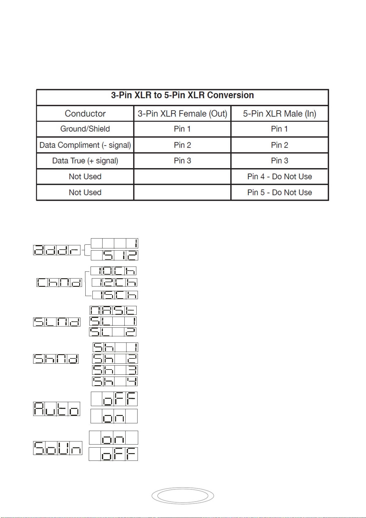
ADDR - DMX Address Setting.
1. Press the either the MENU, UP, or DOWN buttons until “ADDR” is displayed, press ENTER.
2. The current address will now be displayed and flashing. Press the UP or DOWN buttons to find your
desired address. Press ENTER to set your desired DMX address.
CHND - This will let select your desired DMX channel mode.
1. Press the either the MENU button until “CHND” is displayed, press ENTER. Either “10CH”, “12CH” or
“15CH” will be displayed
2. Press the UP or DOWN buttons to find your desired DMX channel mode and press ENTER to confirm
SLND - This will let you set unit as a master or slave in a master/slave configuration.
1. Press the MENU button until “SLND” is displayed, press ENTER. Either “MAST”, “SL 1”, or “SL 2” will
be displayed.
2. Press the UP or DOWN buttons until your desired setting is displayed, press ENTER to confirm.
NOTE: In a Master/Slave configuration you can set one fixture to Master and then set the next fixture to “SL
2”, the fixtures will now have contrast movement to each other.
SHND - Show modes 0-4 (Factory programs). Show mode can run with or without sound
active mode active.
1. Press the MENU button until “SHND” is displayed, press ENTER.
2. “Sh X” will now be displayed, “X” representing a number between 0-4. Shows 1-4 are factory programs,
while show “0” is random mode. Use the UP or DOWN buttons to find your desired show.
3. When you have found your desired show press ENTER, then press and hold the MENU button for at least 3
seconds to activate. After you have set your desired show, it can be changed at any time using the UP or
DOWN buttons.
AUTO- Auto Active mode.
1. Press the MENU button until “Auto” is displayed, press ENTER.
2. The display will show either “ON” or “OFF”. Press the UP or DOWN buttons to select “ON” to activate
sound active mode, or “OFF” to deactivate sound active mode.
3. Press ENTER to confirm.
SOUN - Sound Active mode.
1. Press the MENU button until “SOUN” is displayed, press ENTER.
2. The display will show either “ON” or “OFF”. Press the UP or DOWN buttons to select “ON” to activate
sound active mode, or “OFF” to deactivate sound active mode.
3. Press ENTER to confirm.
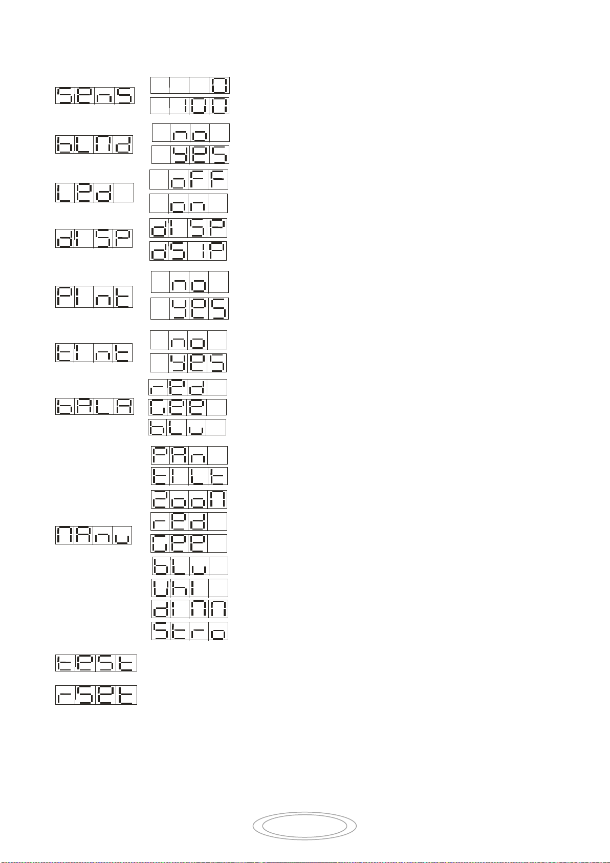
SENS - In this mode you can adjust the sound sensitivity.
1. Press the MENU button until “SENS” is displayed, press ENTER.
2. A number between 0-100 will be displayed. Press the UP or DOWN buttons to adjust the sound sensitivity.
0 being the least sensitive, and 100 being the most sensitive.
3. When you have found your desired setting press ENTER to confirm.

10
BLND- In this mode you can time-out the light.
1. Press the MENU button until “BLND” is displayed, press ENTER.
2. The display will show either “No” or “Yes”. Press the UP or DOWN buttons to select “Yes” to activate
sound active mode, or “No” to deactivate sound active mode.
3. Press ENTER to confirm.
LED - With this function you can have the LED display turn off after 10 seconds.
1. Press the MENU button until “LED” is displayed, press ENTER.
2. The display will show either “ON” or “OFF”. Press the UP or DOWN buttons to select “ON” to keep the
LED display on at all times, or “OFF” to switch to have the LED display switch off after 10 seconds.
3. Press ENTER to confirm. To make you LED display reappear again press any button.
DISP - This function will reverse the display 180º.
1. Press the MENU button until “DISP” is displayed, press ENTER.
2. Press ENTER to “flip” the display. Press ENTER to “flip” it again. Press ENTER when you have made
your desired setup.
PINT - Pan Inversion
1. Press the MENU button until “PINT” is displayed, press ENTER. Either “Yes” or “No” will be displayed.
2. To activate the Pan inversion press the UP or DOWN buttons until “Yes” is displayed, press ENTER to
confirm. To deactivate Pan inversion, select “No” and press Enter.
TINT - Tilt Inversion
1. Press the MENU button until “TINT” is displayed, press ENTER. Either “Yes” or “No” will be displayed.
2. To activate the tilt inversion press the UP or DOWN buttons until “Yes” is displayed, press ENTER to
confim. To deactivate tilt inversion, select “No” and press Enter.
BALA- With this function you can adjust the RGB colors to make your desired color.
1. Press the MENU button until “BALA” is displayed, press ENTER.
2. Use the UP or DOWN buttons to find the color you wish to adjust.
3. Once you find the color you want to adjust press ENTER, the displayed value will begin to flash. Use the UP or
DOWN buttons to adjust the value. Once you have made your adjustment press ENTER.
4. Repeat steps 2-3 until satisfied.
MANU - In this submenu you are able to test the different functions; pan, tilt, LEDs, zoom,
dimmer, and strobe.
1. Press the MENU button until “MANU” is displayed, press ENTER.
2. Use the UP and DOWN buttons to scroll through the various functions able for testing. Once you have found
your desired function you would like to test press ENTER.
3. After you have pressed ENTER, use the UPand DOWN buttons to adjust the values and test the function. To exit
press the MENU button.

11
TEST - This function will run a self test program.
1. Press the MENU button until “TEST” is displayed, press ENTER.
2. The fixture will now run a self test.
RSET - Use this function to reset the unit.
1. Press the MENU button until “RSET” is displayed, press ENTER.
2. The fixture will now reset.
Home Adjustment Menu
To enter the home position adjustment menu, press the ENTER button for at least 5 seconds. In this submenu
you are able to adjust the original position of the pan position, tilt position,
PIAN - adjustment of the pan position.
1. Press the ENTER button for at least 5 seconds, then press the UP or DOWN buttons so that “PINT” is
displayed, press ENTER.
2. Use the UP and DOWN buttons to make your adjustments, and then press ENTER to confirm. Press the
MENU button for one second to exit.
TINT - adjustment of the tilt position.
1. Press the ENTER button for at least 5 seconds, then press the UP or DOWN buttons so that “TINT” is
displayed, press ENTER.
2. Use the UP and DOWN buttons to make your adjustments, and then press ENTER to confirm. Press the
MENU button for one second to exit.
Operation
Universal DMX Control: This function allows you to use a Elation® universal DMX-512 controller to
control the chases and patterns, dimmer and strobe. A DMX controller allows you to create unique programs
tailored to your individual needs.
1. The Inno Pocket Zoom 4 has 3 DMX channel modes; 10 channel mode,12channel mode or 11 channel mode.
See pages 12-14 for detailed description of the DMX values and traits.
2. To control your fixture in DMX mode, follow the set-up procedures on pages 5-7 as well as the set-up
specifications that are included with your DMX controller.
3. Use the controller’s faders to control the various DMX fixture traits.
4. This will allow you to create your own programs.
5. Follow the instruction on page 5 to set the DMX address.
6. For longer cable runs (more than a 100 feet) use a terminator on the last fixture.
7. For help operating in DMX mode consult the manual included with your DMX controller.

12
Sound Active Mode: This mode allows either single unit or several units linked together, to run to the beat
of the music.
1. Press the MENU button until “SOUN” is displayed, and press ENTER. Press the UP or DOWN buttons so
that “ON” is displayed and press ENTER.
2. Press the MENU button until “SENS” is displayed, and press ENTER. Use the UP and DOWN buttons to
adjust the sound
sensitivity. Press ENTER when you have found your desired sensitivity level.
Show Mode: This mode allows either a single unit or several units linked together, to run one of four shows
that you choose.
1. Press the MENU button until “SHND” is displayed, and press ENTER.
2. Press the UP or DOWN buttons until you find your desired show, and press ENTER.
Master-Slave Set Up
Master-Slave Operation This function will allow you to link up to 16 units together and operate without a
controller. The units will be sound activated. In Master-Slave operation one unit will act as the controlling unit
and the others will react to the controlling units programs. Any unit can act as a Master or as a Slave.
1. Using approved DMX data cables, daisy chain your units together via the XLR connector on the rear of the
units. Remember the Male XLR connector is the input and the Female XLR connector is the output. The first
unit in the chain (master) will use the female XLR connector only - The last unit in the chain will use the male
XLR connector only. For longer cable runs we suggest a terminator at the last fixture.
2. On the Master unit press the MENU button until “SLND” is displayed, and press ENTER. Use the UP and
DOWN buttons to scroll to the “MAST” setting and press ENTER.
3. After setting the Master unit to the master setting find your desired operating mode.
4. On the slave units press the MENU button until “SLND” is displayed, and press ENTER. Choose either
“SL 1” or “SL 2” and press ENTER.
5. The slave units will now follow the Master unit.
DMX Channel Mode
Channel Mode
Function
Value
Percent / Setting
9CH
11CH
15CH
1 CH
1CH
1CH
Pan
000-255
0~100%
2 CH
2CH
2CH
Tilt
000-255
0~100%
3CH
3CH
3CH
Zoom
000-255
0~100%
4 CH
Pan/Tilt/Zoom speed
000-255
From fast to slowly
4 CH
4 CH
5 CH
Red
000-255
0~100%
5 CH
5 CH
6 CH
Green
000-255
0~100%
6 CH
6 CH
7 CH
Blue
000-255
0~100%
7 CH
7 CH
8 CH
White
000-255
0~100%
8 CH
8 CH
9 CH
Main dimming
000-255
0~100%

13
9 CH
9 CH
10 CH
Shutter
000-007
008-015
016-131
132-139
140-181
182-189
190-231
232-239
240-247
248-255
Close
Open
Strobe Slow->Fast
Open
Fast Close Slow Open
Open
Fast Open Slow Close
Open
Random Strobe
Open
10 CH
11 CH
Macro Color
000-007
008-011
012-015
016-019
020-022
023-026
027-030
031-034
035-037
038-041
042-045
046-048
049-052
053-056
057-060
061-063
064-067
068-071
072-075
076-078
079-082
083-086
087-089
090-093
094-097
098-101
102-104
105-108
109-112
113-115
116-119
120-123
124-127
128-131
132-135
136-139
140-143
144-147
148-151
152-155
156-159
No function
Color 1
Color 2
Color 3
Color 4
Color 5
Color 6
Color 7
Color 8
Color 9
Color 10
Color 11
Color 12
Color 13
Color 14
Color 15
Color 16
Color 17
Color 18
Color 19
Color 20
Color 21
Color 22
Color 23
Color 24
Color 25
Color 26
Color 27
Color 28
Color 29
Color 30
Color 31
Color 32
Color Macro 1
Color Macro 2
Color Macro 3
Color Macro 4
Color Macro 5
Color Macro 6
Color Macro 7
Color Macro 8

14
160-163
164-167
168-171
172-175
176-179
180-183
184-187
188-191
192-195
196-199
200-203
204-207
208-211
212-215
216-219
220-223
224-227
228-231
232-235
236-239
240-243
244-247
248-251
252-255
Color Macro 9
Color Macro 10
Color Macro 11
Color Macro 12
Color Macro 13
Color Macro 14
Color Macro 15
Color Macro 16
Color Fade Macro 1
Color Fade Macro 2
Color Fade Macro 3
Color Fade Macro 4
Color Fade Macro 5
Color Fade Macro 6
Color Fade Macro 7
Color Fade Macro 8
Color Fade Macro 9
Color Fade Macro 10
Color Fade Macro 11
Color Fade Macro 12
Color Fade Macro 13
Color Fade Macro 14
Color Fade Macro 15
Color Fade Macro 16
11 CH
12 CH
Macro Color Speed
000-255
Color change form slowly to fast
13 CH
Pan/Tilt Macro
000-015
016-035
036-055
056-075
076-095
096-115
116-135
136-155
156-175
176-195
196-215
216-235
236-255
No function
Macro 1
Macro 2
Macro 3
Macro 4
Macro 5
Macro 6
Macro 7
Macro 8
Macro 9
Macro 10
Macro 11
Macro 12
14 CH
Pan/Tilt Macro speed
000-255
Pan/Tilt Macro speed form slowly to fast
10 CH
12 CH
15 CH
Function
000-069
070-079
080-179
180-189
190-199
200-209
210-255
No function
Blackout while Pan/Tilt Move
No function
Auto running mode
No function
Reset All
No function

15
Photometric Chart
Dimmer Curve Chart

16
Fuse Replacement
Locate and remove the unit’s power cord. Once the cord has been removed located the fuse holder located
inside the power socket. Insert a flat-head screw driver into the power socket and gently pry out the fuse
holder. Remove the bad fuse and replace with a new one. The fuse holder has a built-in socket for a spare fuse
be sure not to confuse the spare fuse with active fuse.
Cleaning
Due to fog residue, smoke, and dust cleaning the internal and external optical lenses and mirror should be carried
out periodically to optimize light output. Cleaning frequency depends on the environment in which the fixture
operates (I.e. smoke, fog residue, dust, dew). In heavy club use we recommend cleaning on a monthly basis.
Periodic cleaning will ensure longevity, and crisp output.
1. Use normal glass cleaner and a soft cloth to wipe down the out- side casing.
2. Use a brush to wipe down the cooling vents and fan grill.
3. Clean the external optics with glass cleaner and a soft cloth every 20 days.
4. Clean the internal optics with glass cleaner and a soft cloth every 30-60 days.
5. Always be sure to dry all parts completely before plugging the unit back in.
Trouble Shooting
Trouble Shooting: Listed below are a few common problems that you may encounter, with solutions.
No light output from the unit;
1. Be sure the external fuse has not blown. The fuse is located on the rear panel of the unit.
2. Be sure the fuse holder is completely and properly seated.
Unit does not respond to sound;
1. Low frequencies (bass) should cause the unit to react to sound.
Tapping on the microphone, quiet or high pitched sounds may
not activate the unit.
Specifications
Model: MJ-1038
Voltage: 100 - 240V, 50/60Hz
LED: 4 x 12W 4-in-1 RGBW LEDs
Power Consumption: 26W @ 120V
75W @ 230V
Dimensions: 5. 5”(L) x 6.75”(W) x 9.75”(H)
141mm x 174mm x 247mm
Weight: 7 Lbs. / 3.2 kgs.
Beam Angle: 10-60 Degrees
Fuse: 3 Amp
Duty Cycle: None
DMX:3 DMX Channel Modes: 10 Channel Mode, 12 Channel Mode & 15 Channel Mode
Colors: RGBW color mixing
Sound Active: Yes
Working Position: Any Safe, Secure Position
This manual suits for next models
2
Table of contents
Other MJ LED LIGHTNING Dj Equipment manuals
Popular Dj Equipment manuals by other brands

thomann
thomann STAIRVILLE Outdoor Stage PAR 12 X 3W Tri user manual

FOS Technologies
FOS Technologies FOS ACL Line 12 manual

MC Crypt
MC Crypt CMP-920USB instruction manual

afx light
afx light CLUB-710-IP user manual

Gamma+
Gamma+ Nano Beam user manual

Claypaky
Claypaky ALPHA WASH EASY 1200 instruction manual