• Refasten the cover
• Switch on and check for correct operation ensuring
the green indicator LEDs are illuminated
• We recommend, on commissioning the installation, a
minimum charge period of 24 hours before carrying
out an emergency duration test
• The indicator lamp marked “CHARGE” will be lit
when the battery is charging. If it is not lit, check that
the battery is connected to the PCB, and that there
is a 230V mains supply. The indicator lamp marked
“LAMPS” will be lit if the lamp circuit is complete
and the lamps are healthy. (NB the indicator lamps
will not work when the fitting is in emergency mode,
only while it is connected to the mains supply)
3
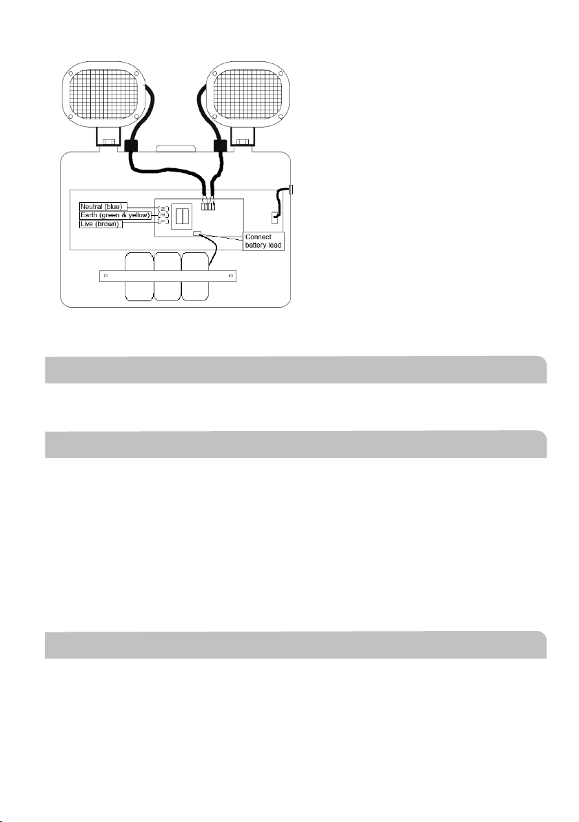
Fig. 2
•Refasten the cover
•Switch on and check for correct operation ensuring the green indicator LEDs are illuminated
•We recommend, on commissioning the installation, a minimum charge period of 24 hours before
carrying out an emergency duration test
The indicator lamp marked “CHARGE” will be lit when the battery is charging. If it is not lit, check that the battery
is connected to the PCB, and that there is a 230V mains supply. The indicator lamp marked “LAMPS” will be lit if
the lamp circuit is complete and the lamps are healthy. (NB the indicator lamps will not work when the fitting is in
emergency mode, only while it is connected to the mains supply)
WARNING
This product must be disconnected from the circuit if subjected to any high voltage or insulation resistance
testing. Irreparable damage will occur if this instruction is not followed
GENERAL
This product should be recycled in the correct manner when it reaches the end of its life. Check local authorities
for where facilities exist
If the batteries have been left in a discharged state for a long period of time, we recommend that one or more
charge and discharge cycles are performed, to restore the battery to its full capacity
The batteries in this luminaire are Nickel Cadmium and must be disposed of correctly. Please contact local
authorities for the disposal of this toxic waste
Clean with a soft dry cloth only, do not use aggressive cleaning products or solvents which may damage the
product
WARRANTY
This product has a warranty of 3 years (excluding battery) from date of purchase. Failure to install this product in
accordance with the current edition of the IEE Wiring Regulations, improper use, or removal of the batch codes
Fig. 2
WARNING
GENERAL
This product must be disconnected from the circuit if subjected to any high voltage or insulation resistance
testing. Irreparable damage will occur if this instruction is not followed
This product should be recycled in the correct manner when it reaches the end of its life. Check local
authorities for where facilities exist
If the batteries have been left in a discharged state for a long period of time, we recommend that one or
more charge and discharge cycles are performed, to restore the battery to its full capacity
The batteries in this luminaire are Nickel Cadmium and must be disposed of correctly. Please contact local
authorities for the disposal of this toxic waste
Clean with a soft dry cloth only, do not use aggressive cleaning products or solvents which may
damage the product
This product is non-dimmable
WARRANTY
This product has a warranty of 3 years (excluding battery) from date of purchase. Failure to install this
product in accordance with the current edition of the IEE Wiring Regulations, improper use, or removal of
the batch codes will invalidate the warranty. If this product should fail within its warranty period it should
be returned to the place of purchase for a free of charge replacement. ML Accessories does not accept
responsibility for any installation costs associated with the replacement product. Your statutory rights are not
affected. ML Accessories reserve the right to alter product specification without prior notice.