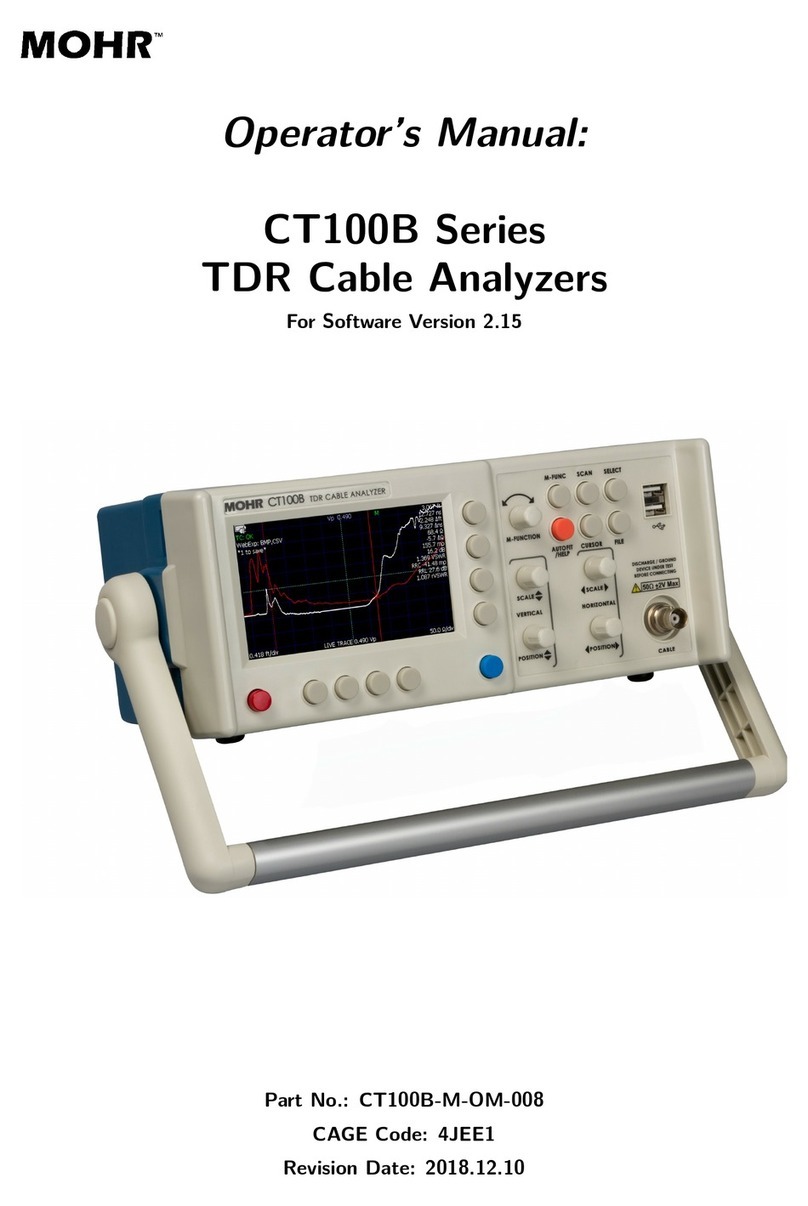
Mohr CT100 User manual

Operator's Manual
CT100 and CT100HF
Automated Metallic Time-Domain Reflectometers
Part No.: CT100-M-OM-004
CAGE Code: 4JEE1
Revised: August 12, 201

Copyright Notice
Copyright Notice
Copyright © 2013 MOHR Test and Measurement LLC (MOHR). ll rights reserved.
Reproduction of this manual in print and electronic form is authorized for U.S. Government purposes only. This
manual may not be reproduced, distributed, transmitted, displayed, published or broadcast in any form or medium by
any other party without written permission from MOHR.
MOHR products are covered by U.S. and foreign patents, issued and pending. Information in this publication
supersedes all previously published material. MOHR reserves the right to change product specifications or pricing at
any time without notice.
MOHR Test and Measurement, 1440 gnes Street, Richland, W 99352 US
ii

Warranty
Warranty
Purchase and/or use of this product signifies your agreement to the terms of this Warranty. MOHR Test and
Measurement LLC (MOHR) warrants that this product will be free from defects in materials and workmanship for a
period of one (1) year from the date of shipment. If any such product proves defective during this warranty period,
MOHR, at its option, either will repair the defective product without charge for parts and labor, or will provide a
replacement in exchange for the defective product.
In order to obtain service under this Warranty, customers must notify MOHR of the defect before the expiration of the
warranty period and make suitable arrangements for the performance of service. Customers shall be responsible for
packaging and shipping the defective product to MOHR with shipping charges prepaid. Customer shall be
responsible for paying all return shipping charges, duties, taxes, and other charges for units returned to any location.
This Warranty is given by MOHR with respect to this product in lieu of any other warranties expressed or implied.
MOHR and its vendors disclaim any implied warranties of merchantability or fitness for a particular purpose. MOHR’s
responsibility to repair or replace defective units is the sole and exclusive remedy provided to the customer for breach
of the Warranty. MOHR and its vendors will not be liable for any indirect, special, incidental, or consequential
damages irrespective of whether MOHR or the vendor has advance notice of the possibility of such damages.
Specific limitations of this Warranty:
This Warranty only applies to normal and reasonable use of this product. Damage to this product resulting
from improper use, the determination of which is solely at the discretion of MOHR, is specifically excluded
from this Warranty.
Electrical damage to this product resulting from connection of a cable or device carrying a static electrical
charge to the front panel BNC connector or SMA connector without first properly grounding the conducting
elements of the cable or device is specifically excluded from this Warranty.
Electrical damage to this product resulting from connection of a cable or device carrying an electrical signal
or other non-zero electrical potential relative to earth ground to the front panel BNC connector or SMA
connector is specifically excluded from this Warranty.
iii

Contacting
Contacting MOHR Test and Measurement
MOHR Test and Measurement
Phone
Phone
Sales 1-509-946-0941
Technical Support 1-509-946-2240
Toll-free 1-888-852-0408
Mail
Mail
MOHR Test and Measurement
1440 gnes Street
Richland, W 99352
US
E-mail
E-mail
Web
Web
www.mohr-engineering.com
iv

Table o Contents
Table o Contents
Copyright Notice.................................................................................................................................ii
Warranty.............................................................................................................................................iii
Contacting MOHR Test and Measurement.......................................................................................iv
Phone............................................................................................................................................iv
Mail................................................................................................................................................iv
E-mail............................................................................................................................................iv
Web...............................................................................................................................................iv
General Information............................................................................................................................1
Product description........................................................................................................................1
Battery pack and C power requirements.....................................................................................2
Options and accessories................................................................................................................2
Unpacking and initial inspection....................................................................................................2
Repacking for shipment.................................................................................................................2
Safety Summary.................................................................................................................................5
Terms in the manual......................................................................................................................5
Terms on the product.....................................................................................................................5
D NGER....................................................................................................................................5
W RNING ................................................................................................................................5
C UTION...................................................................................................................................5
Symbols in the manual...................................................................................................................6
Symbols on the product.................................................................................................................6
Static charge..................................................................................................................................6
Fuses.............................................................................................................................................6
C power source...........................................................................................................................6
Grounding the CT100....................................................................................................................7
Danger arising from loss of ground................................................................................................7
Explosive atmospheres..................................................................................................................8
Do not remove covers or panels....................................................................................................8
Connecting cables to the front panel BNC....................................................................................8
Battery replacement and disposal.................................................................................................8
Operating Instructions........................................................................................................................9
Overview........................................................................................................................................9
Handling.....................................................................................................................................9
Powering the CT100..................................................................................................................9
Caring for the battery...............................................................................................................10
Charging and power status......................................................................................................10
Batteries and long-term storage..............................................................................................11
Low battery..............................................................................................................................11
v

Preparing to use the CT100.........................................................................................................12
Front panel controls and connectors...........................................................................................12
Rear panel connectors and switches...........................................................................................15
Setting up the CT100...................................................................................................................16
Setting date and time...............................................................................................................16
Navigating dialog boxes..........................................................................................................16
Display features...........................................................................................................................17
License codes..............................................................................................................................17
Menu selections and function buttons.........................................................................................18
M-FUNC button........................................................................................................................18
SC N button and menu...........................................................................................................18
SELECT button........................................................................................................................20
UTOFIT..................................................................................................................................20
CURSOR.................................................................................................................................20
LIBR RY button and menu.....................................................................................................20
MENU button and top-level menu selections..........................................................................21
Test preparations.........................................................................................................................32
Velocity of propagation............................................................................................................32
Change Vp...............................................................................................................................32
Find an unknown Vp................................................................................................................33
Temperature correction...........................................................................................................34
Cable test procedures..................................................................................................................34
Distance to fault.......................................................................................................................34
Common types of cable faults.................................................................................................37
Reflection coefficient measurements......................................................................................39
Return loss measurements......................................................................................................39
Ohms-at-cursor........................................................................................................................40
VSWR......................................................................................................................................40
Relative distance measurements............................................................................................40
Scan a trace.............................................................................................................................41
Select a trace...........................................................................................................................41
Store a trace............................................................................................................................43
Load a trace (cable records)....................................................................................................44
Storage space..........................................................................................................................45
View the difference between traces........................................................................................46
View a first derivative of a trace...............................................................................................47
View a Fast Fourier Transform of a trace................................................................................47
View S-Param trace.................................................................................................................48
Calibrated S-Param trace........................................................................................................48
Remote control........................................................................................................................48
Cable type................................................................................................................................49
Measurement...........................................................................................................................49
Configurations..........................................................................................................................52
CT Viewer™.....................................................................................................................................53
Options and ccessories.................................................................................................................55
vi

Options ........................................................................................................................................55
ccessories .................................................................................................................................55
Standard accessories (CT100)................................................................................................55
Standard high-frequency accessories (CT100HF)..................................................................55
Optional accessories (CT100 / CT100HF)..............................................................................56
Service accessories (CT100 / CT100HF)................................................................................56
ppendix : Specifications..............................................................................................................57
Electrical specifications................................................................................................................57
Mechanical specifications............................................................................................................59
Weight......................................................................................................................................59
Dimensions..............................................................................................................................59
Environmental specifications.......................................................................................................59
Temperature............................................................................................................................59
Certifications and Compliances...................................................................................................60
EC............................................................................................................................................60
FCC Compliance.....................................................................................................................60
ppendix B: Subassembly Drawings and Parts List.......................................................................61
Subassembly drawings................................................................................................................61
Parts list.......................................................................................................................................68
ppendix C: Operator Performance Check....................................................................................71
General information.....................................................................................................................71
Required equipment.....................................................................................................................71
Getting ready................................................................................................................................71
Reflected Rise Time Check (10-90%).........................................................................................72
Reflected Rise Time Check (20-80%).........................................................................................73
Jitter, Noise, and Sampling Efficiency Check..............................................................................73
Output Impedance Check............................................................................................................73
Pulse mplitude Check................................................................................................................74
Pulse Width Check.......................................................................................................................74
Pulse Repetition Rate Check.......................................................................................................74
Sequential Sampling Rate Check................................................................................................75
Vertical Scale Check....................................................................................................................75
Vertical ccuracy Check..............................................................................................................75
Vertical Position Check................................................................................................................75
Input Susceptibility Check............................................................................................................75
Distance Cursor Resolution Check..............................................................................................75
Cursor Readout Range Check.....................................................................................................75
Cursor Readout Resolution Check..............................................................................................76
Distance Measurement ccuracy Check.....................................................................................76
Ohm Readout Range Check........................................................................................................76
Resolution Check.........................................................................................................................76
Vertical ccuracy Check..............................................................................................................77
Horizontal Scale Check................................................................................................................77
Horizontal Range Check..............................................................................................................77
Horizontal Position Check............................................................................................................77
vii

Pulse Frequency Check...............................................................................................................77
ppendix D: Calibration Procedures...............................................................................................79
General information.....................................................................................................................79
Calibration interval.......................................................................................................................79
Required equipment.....................................................................................................................79
Getting ready................................................................................................................................79
Pulse measurement checks (optional).........................................................................................80
Turn off temperature adjustment.................................................................................................80
Set manual calibration values......................................................................................................81
Capacitive load calibration...........................................................................................................81
Driver start calibration..................................................................................................................82
Resistive load calibration.............................................................................................................82
Vertical calibration........................................................................................................................82
Manually verify calibration values................................................................................................82
Manually verify capacitive calibration......................................................................................82
Manually verify resistive load calibration.................................................................................84
Enable temperature adjustment...................................................................................................87
Horizontal calibration...................................................................................................................87
Clear temperature lookup table...................................................................................................89
ppendix E: Operator Troubleshooting...........................................................................................91
General information.....................................................................................................................91
Power on test...............................................................................................................................91
Functional block diagram and troubleshooting flowcharts...........................................................91
ppendix F: Vp of Common Cables..............................................................................................103
Cable types................................................................................................................................103
Dielectric material..................................................................................................................103
RG standards.........................................................................................................................103
MIL-C-17 standards...............................................................................................................104
Commercial designations......................................................................................................105
Twisted pair...........................................................................................................................105
ppendix G: Maintenance and Service Instructions.....................................................................107
Cleaning and lubrication............................................................................................................107
Cleaning and lubrication interval................................................................................................107
Battery removal..........................................................................................................................107
Inspection...................................................................................................................................108
Inspection interval......................................................................................................................108
Calibration and calibration interval.............................................................................................108
Glossary.........................................................................................................................................109
Index...............................................................................................................................................115
viii

List o Figures
List o Figures
Figure 1: Diagram of the front panel of the CT100 / CT100HF......................................................12
Figure 2: Diagram of the rear panel of the CT100 / CT100HF.......................................................15
Figure 3: Screenshot showing typical features of the CT100 display.............................................17
Figure 4: Screenshot showing UTOFIT result..............................................................................33
Figure 5: Screenshot showing Vp determination............................................................................34
Figure 6: UTOFIT cable................................................................................................................35
Figure 7: fter adjusting the vertical scale......................................................................................36
Figure 8: zoomed-in view of the cable fault.................................................................................36
Figure 9: n open cable fault..........................................................................................................37
Figure 10: short cable fault..........................................................................................................37
Figure 11: n open cable fault at 1000 ft........................................................................................38
Figure 12: 50 Ω to 75 Ω BNC to SM interconnect.....................................................................41
Figure 13: Screenshots showing selection of a live trace...............................................................42
Figure 14: Saving a trace................................................................................................................43
Figure 15: Loading a trace..............................................................................................................44
Figure 16: Difference trace..............................................................................................................46
Figure 17: First-derivative plot.........................................................................................................47
Figure 18: CT100 complete mechanical and electrical assembly..................................................62
Figure 19: CT207 (power) subassembly.........................................................................................63
Figure 20: CT208 (analog) subassembly........................................................................................64
Figure 21: CT209 (back panel) subassembly.................................................................................65
Figure 22: CT290 (front panel) subassembly.................................................................................66
Figure 23: CT290HF (front panel) subassembly.............................................................................67
Figure 24: Trace preparation for rise time measurement...............................................................72
Figure 25: Cursor placement for determination of 10-90% rise time..............................................73
Figure 26: Example of an incomplete capacitive calibration...........................................................83
Figure 27: Example of a correctly set capacitive calibration...........................................................84
Figure 28: Typical trace from a CT100 with a shorting terminator applied to the test port.............85
Figure 29: Hybrid Comp adjustment with open BNC and cursor at the reflected rise....................85
Figure 30: Hybrid Comp adjustment with open terminator, detail...................................................86
Figure 31: Hybrid Comp adjustment with the shorting terminator..................................................86
Figure 32: Hybrid Comp adjustment with the shorting terminator, detail........................................87
Figure 33: Identification of cable start position...............................................................................88
ix

List o Tables
List o Tables
Electrical specifications....................................................................................................................57
Mechanical specifications: weight....................................................................................................59
Mechanical specifications: dimensions............................................................................................59
Environmental specifications............................................................................................................59
Subassemblies and parts list...........................................................................................................68
Cable types: Dielectric materials....................................................................................................103
Cable types: RG standards............................................................................................................103
Cable types: MIL-C-17 standards..................................................................................................104
Cable types: Commercial designations..........................................................................................105
Cable types: Twisted pair...............................................................................................................105
x

General In ormation
General In ormation
Product description
Product description
The MOHR CT100 / CT100HF utomated Metallic Time-Domain Reflectometers (MTDRs) use a
form of closed-circuit radar known as Time-Domain Reflectometry (TDR) to test cables for defects.
These instruments apply a very fast risetime step signal to the cable under test and then measure
the reflected voltage at very short time intervals. The resultant TDR trace allows the operator to
identify changes in impedance within the cable indicating the presence of faults such as opens,
shorts, kinks, defects in the shield or conductor, foreign substances such as water, or thermal
damage. The CT100 and CT100HF can find extremely subtle cable defects that may be missed
by other testing devices.
The CT100 series TDRs have specifications unmatched by any other commercially-available
metallic TDR cable tester. Both devices feature timebase resolution of 0.76 ps regardless of cable
length, equivalent to approximately 75 μm in coaxial cable with a Vp of 0.66. This allows for
extremely precise cable length measurements and localization of cable defects. Fast system
risetimes ensure excellent spatial resolution and make these instruments particularly valuable for
troubleshooting modern high-frequency analog/RF and digital communications systems.
The CT100 is able to perform continuous sequential sampling at up to 250 kHz, continuously
acquiring up to 500 full 500-point TDR traces per second. In concert with the CT100's high-speed
internal 32-bit processor, this allows for rapid automated cable scans, sophisticated real-time
digital filtering techniques (averaging, subtraction, derivatives, and more), and accurate
characterization of transient cable defects.
The CT100 can store hundreds of full-length high-resolution cable scans or several thousand
short or lower-resolution cable scans in its standard 2 GB internal non-volatile flash memory.
These scans are easy to call up for comparison so that changes in cable integrity over time can be
accurately assessed. To enter data, use the built-in software keyboard or plug an external
barcode reader or keyboard into the front-panel USB connector. It is easy to connect the CT100
to a host PC using 10/100 Ethernet or USB to view, analyze, and store your data.
In the remaining sections, the specific requirements, capabilities, and operation of the CT100 and
CT100HF are described in detail. Unless otherwise specified, any reference to the CT100 is true
of the CT100HF as well. Figures in this text were acquired using both CT100 and CT100HF
devices.
Mohr CT100 / CT100HF Operator's Manual 1

General Information
Battery pack and AC
Battery pack and AC power requirements
power requirements
The CT100 may be operated using either the supplied C adapter, the internal NiMH batteries (for
a minimum 6 hours operating time, typical use), or optional hot-swappable external 14.4 VDC
battery packs (for unlimited portable use). The internal NiMH battery charges under C during
normal operation.
The external C power adapter is intended to be used with either a 120 V C or 240 V C RMS
power source. Use of a standard 3-prong C socket with intact ground connection is essential for
safe operation of the CT100 with the included C power adapter. Review the Safety Summary
section before operating the CT100.
Options and accessories
Options and accessories available for the CT100 are described on page 53.
Unpacking
Unpacking and initial
and initial inspection
inspection
Before opening the shipping package containing the CT100, first inspect it for signs of damage. If
there is evidence of damage to the shipping package, notify both the shipping carrier and MOHR.
The shipping container should contain the CT100 and standard accessories, including an
Operator's Manual, front panel cover, external C adapter and power cord, soft transit case, and
calibration fixture(s). If the shipping container is intact but there are missing items or if the CT100
is damaged, defective, or does not meet operational requirements, contact a MOHR-authorized
sales representative.
Repacking
Repacking or shipment
or shipment
When the CT100 needs to be shipped to a MOHR-authorized service center for repair, calibration,
or other service, affix a label to the outside of the shipping container indicating the name, address,
phone, and e-mail of the owner, the name of the MOHR service representative who was contacted
regarding the shipment, the serial number of the instrument, and a description of the problem with
the instrument and/or the desired service or maintenance.
Optimally, the original shipping carton and packing material should be used to repack the CT100
for shipment. Otherwise, the following steps should be taken:
1) Obtain a heavy-duty corrugated cardboard box at least 6 in. (15 cm) larger in each dimension
than the equipment to be shipped to allow for protective cushioning material. The shipping
carton should have at least 200 lb. (90.7 kg) test strength.
2) Make sure the CT100 is turned off by setting the rear panel power switch to the OFF position.
3) Install the front panel cover.
2 Mohr CT100 / CT100HF Operator's Manual

General Information
4) Wrap the CT100 in polyethylene sheeting to protect the case.
5) Place the CT100 in its soft case.
6) Cushion the CT100 on all sides with equal amounts of urethane foam or other firm packing
material so that the instrument is centrally situated in the shipping container and there is no
free space for the CT100 to move about during shipment.
7) Seal the container with packing tape.
Mohr CT100 / CT100HF Operator's Manual 3

Sa ety Summary
Sa ety Summary
The safety information presented in this brief summary is only intended for operators of the CT100
and CT100HF. Safety information relating to specific circumstances is present throughout this
manual and is not necessarily present in this summary. Please read this manual in its entirety
before using the CT100 and take note of safety information not included in this summary.
Terms in the manual
Terms in the manual
ARNING: Refers to conditions or practices that could result in personal injury
or loss of life.
CAUTION: Refers to conditions or practices that could result in damage to this
product or other products and in some cases could void the arranty.
Terms on the product
DANGER
Indicates an injury hazard immediately accessible as you read the marking.
WARNING
Indicates an injury hazard not immediately accessible as you read the marking.
CAUTION
Indicates a hazard to property including the product.
Mohr CT100 / CT100HF Operator's Manual 5

Safety Summary
Symbols in the manual
Symbols on the product
Static
Static charge
charge
ny cable or wire can carry a significant static electric charge that could damage the sensitive
electronics of the CT100/CT100HF. For this reason, it is essential to ground any cable or device
about to be tested before attaching it to the front panel BNC or SM adapter.
CAUTION: Failure to properly ground the cable / device under test prior to
connecting it to the front panel connector, either directly or indirectly, could result
in damage to the sampling electronics and will void the arranty.
Fuses
Fuses
There are no external fuses or breakers accessible to the user. However, there are two internal
automatic thermal breakers that disconnect the power from the charger and battery to the rest of
the system. These thermal breakers make an audible click when they actuate. One of the circuit
breakers automatically resets after time. When this breaker cools, the CT100 can be restarted.
There is also a breaker on the CT207 subassembly 4 charger board. If tripped, this breaker
must be reset by taking the rear case off, locating the breaker assembly, and pushing its reset tab.
The tab is located at the far end of the board, nearest to the fan.
CAUTION: If the thermal breakers occasionally trip, the instrument should be
evaluated by qualified service personnel for maintenance.
AC power source
AC power source
The CT100 is intended to operate only from a 120 V C or 240 V C RMS power source using the
CE- and UL-approved 24 VDC external power supply / adapter provided with the instrument.
6 Mohr CT100 / CT100HF Operator's Manual

Safety Summary
ARNING: Only use the power cord supplied with the instrument, and then only
if the cord is in good condition. Refer all maintenance regarding the power
supply or power cord to qualified service personnel.
CAUTION: Use of any power source other than the supplied external power
adapter(s) could damage the instrument and may void the arranty. Use only
MOHR-approved accessories.
ARNING: To reduce the risk of electric shock, disconnect all external cables
before connecting the 24 VDC external power supply.
Grounding the CT100
Grounding the CT100
When the CT100 is connected to the external C adapter, the CT100 chassis, front panel USB,
screen, and controls are grounded through the grounding conductor of the power cord. To avoid
electrical shock, it is essential that the protective ground connection is present when operating the
unit under C power. When disconnected from external power, the CT100 is floating relative to
earth ground, unless one of the USB ports is connected to a grounded device. In this case, the
ground of the USB device is common with the CT100 chassis, screen, and electronic controls. n
isolated ground power supply is an optional accessory available upon request.
t all times, the front panel BNC connector is floating and is isolated by at least 500 VDC from the
remainder of the CT100. This eliminates measurement errors caused by common-mode noise
and slight ground-potential differences in the the cable / device under test. However, care should
be taken with respect to electrical safety, as the front panel BNC shield is never safely grounded
unless connected to a safely-grounded cable or device and can be considered a second live
conductor if connected to a cable or device carrying a non-zero electrical potential relative to earth
ground. This situation carries the risk of electric shock.
ARNING: The BNC connector shield represents a floating ground and is never
safely grounded even with the use of a properly grounded AC adapter. Never
use the CT100 to test any cable or device carrying a non-zero electrical potential
relative to earth ground, as this could render an electric shock.
Danger arising rom
Danger arising rom loss o ground
loss o ground
When disconnected from the C power adapter, the CT100 is no longer grounded unless
connected to a grounded USB device. Because the BNC connector shield is floating relative to
the remainder of the instrument, the BNC connector may be operating at an elevated voltage even
when the C adapter is connected. Therefore, the BNC connector should never be used to test
any cable or device with an electrical potential relative to earth.
Mohr CT100 / CT100HF Operator's Manual 7

Safety Summary
ARNING: Upon loss of the protective-ground connection, all accessible parts,
including the screen, knobs, and connectors, can render an electric
shock.
Explosive atmospheres
Do not operate the CT100 in an explosive atmosphere unless your unit has been specifically
certified for that condition. Explosive tmospheres: MIL-STD 810G, Method 511.5, Procedure I
(+55°C, sea level to 4600 m).
Do not remove
Do not remove covers
covers or
or panels
panels
To avoid personal injury and risk of electric shock, do not open the CT100 case and do not
operate unless the case is fully intact.
Connecting cables to the ront panel BNC
To avoid damage to the CT100 and the very sensitive sampling electronics associated with the
front panel BNC connector, do not connect it to any cable or device that can be driven by active
circuitry or is subject to transient voltage spikes.
ARNING and CAUTION: The instrument should never be used to test any
cable or device carrying live electrical signals, as this carries a risk of electric
shock. This could also damage the sampling electronics and will void the
arranty.
CAUTION: Always properly ground the conductor(s) of any cable or wiring to
remove any static charge prior to connecting it, either directly or indirectly
through attachment to another cable, to the CT100's front panel BNC connector.
Failure to do so can damage the instrument's sensitive sampling electronics and
will void the arranty.
Battery replacement and
Battery replacement and disposal
disposal
The CT100 contains a 2700 m ·h internal battery pack consisting of 12 NiMH batteries, as
well as a single lithium coin cell battery for the internal clock. Depending on the state or local
jurisdiction, these batteries may require special disposal and/or recycling. Contact your local
authorities for safe disposal in your area, or you may return them to MOHR Test and
Measurement LLC for recycling.
8 Mohr CT100 / CT100HF Operator's Manual

Operating Instructions
Overview
Overview
Handling
The CT100 is designed to meet the rigors associated with normal instrument use both in the
field and on the benchtop. Care should be taken to protect it from excessive mechanical
shock, vibration, static electrical charges, and water hazards.
The CT100 front panel is protected from impact by a snap-on front cover, in which an optional
small-format version of the Operator's Manual can be stored. The carrying handle rotates 360°
and can be used to support the instrument for bench-top use.
The CT100 is not watertight and must be protected against water spray. If the unit is subjected
to water spray, first turn off the unit with the battery-disconnect power switch on the rear panel
and then drain all of the excess water from the case and allow it to dry completely.
s noted in the Safety Summary and elsewhere, the CT100 and CT100HF are sensitive to
damage introduced by electrostatic discharge. lways properly ground the center conductor of
a cable before attaching it, either directly or indirectly, to the front panel BNC or SM
connector. Failure to do so could damage the sampling electronics and void the Warranty.
The CT100 can be stored in temperatures of between -20°C to +60°C with or without a battery
installed and can be operated from 0°C to +50°C.
Powering the CT100
The CT100 can be powered through the included 120/240 V C (RMS) to 24 VDC external
power adapter. This adapter has sufficient capacity to charge the internal battery from a dead
battery state while the unit is under operation. The internal battery will allow the unit to operate
using power conservation techniques for periods of at least 6 hours under typical use.
utomatic power-down occurs after a variable amount of time of inactivity, selectable in
software by the user. The screen also can be set to turn off after a set amount of inactivity.
heavily discharged battery will require 2.5 hours to reach full charge.
There is an option to use external, hot-swappable 14.4 VDC NiMH battery packs to power the
CT100. These battery packs plug into the back panel external battery connector and can be
charged while the CT100 is run on C power. When connected, the device automatically
powers off of the external battery pack until it is discharged. By default, the CT100 charges
the internal battery until full before charging the external battery.
Mohr CT100 / CT100HF Operator's Manual 9

Operating Instructions
Fusing is internal and based on thermal reset switches and a manual-reset breaker located on
CT207 subassembly 4. If one of these fuses trips, it may indicate that a hardware
malfunction has occurred. Diagnostic steps should be taken to determine this.
Caring or the battery
The CT100 has an intelligent internal battery-charging circuit that dynamically determines the
optimum charge rate and reverts to low-level trickle charge when the battery is fully charged.
Charging is automatic and there are no charge-length restrictions.
The battery should be charged between 0ºC and +45ºC. Battery operation should be limited to
between 0ºC and +50ºC. Batteries should be stored between -20ºC and +60ºC. If the battery
pack is older, it may not show a 100% charge capacity even when the maximum battery
charge is obtained.
CAUTION: Do not attempt to charge the battery pack below 0ºC or above +45ºC.
Batteries should not be stored below -20ºC or above +60ºC.
Charging and power status
The CT100 operates from a 24 volt power adapter, internal battery pack, or an external battery
pack. When plugged into an adapter, the CT100 will preferentially charge the internal battery
pack over any connected external pack. When operating off of batteries, the CT100 will prefer
to use an external battery pack over the internal battery pack.
When an external battery pack is connected and fully charged, the CT100 will return to trickle-
charge the internal battery pack. However, as long as the internal pack remains fully charged,
the CT100 will immediately switch to charging the external battery each time it is disconnected
and a external pack is reconnected. In this fashion, a single CT100 can be used to charge
several external battery packs in sequence.
In the Power menu, a submenu of the Main menu, the user can set power save and shutdown
timers. Different time-out values can be set for when the CT100 is using the C/DC converter
or batteries. In power save mode, the screen goes blank and only enough power is used to
monitor for user input. When input is received, the CT100 wakes back up. When a shutdown
timer expires, the CT100 will turn off.
lso in the Power menu, the user can toggle the Charge External/Internal option to determine
which battery pack has priority when charging. By default, the CT100 will charge the internal
battery pack until it is full, then switch to charging the external battery pack. The functions of
the external battery can be toggled on and off in the same menu. When off, external battery
voltage and charge state will not be displayed.
voltage readout can be turned off and on with the Power Display menu option in the Power
menu. The battery will have its voltage displayed on the screen, along with the voltage from
the 24 volt adapter if it’s attached. The color of the voltage text indicates the state of the power
10 Mohr CT100 / CT100HF Operator's Manual

Operating Instructions
source. If green, then that source is powering the CT100. If red, then that source is being
charged.
Batteries and long-term storage
The CT100 has NiMH internal batteries. These batteries will drain if the CT100 is left in
storage over long periods.
To preserve battery charge for as long as possible during storage, make sure the power switch
on the back of the CT100 is set to the OFF position.
fter several months of storage, the internal batteries may be completely drained. llow up to
24 hours for the first re-charge of the CT100 after coming out of long-term storage.
Low battery
When a low battery condition is first encountered, the CT100 alerts the user with a red
warning. n “Internal Battery Low” message appears when the battery percentage left drops
below 20 percent.
Mohr CT100 / CT100HF Operator's Manual 11
This manual suits for next models
1
Table of contents
Other Mohr Measuring Instrument manuals
Popular Measuring Instrument manuals by other brands

Amprobe
Amprobe MO-100 user manual

Integrated Meterting Systems
Integrated Meterting Systems MS120S01 Technical specifications and installation instructions

VOLTCRAFT
VOLTCRAFT VBM-100 operating instructions

Norav Medical
Norav Medical NR-1207-E Installation and operation guide

Galvanic Applied Sciences
Galvanic Applied Sciences ProTech903 Operation manual

Bartec
Bartec Tech500 user guide