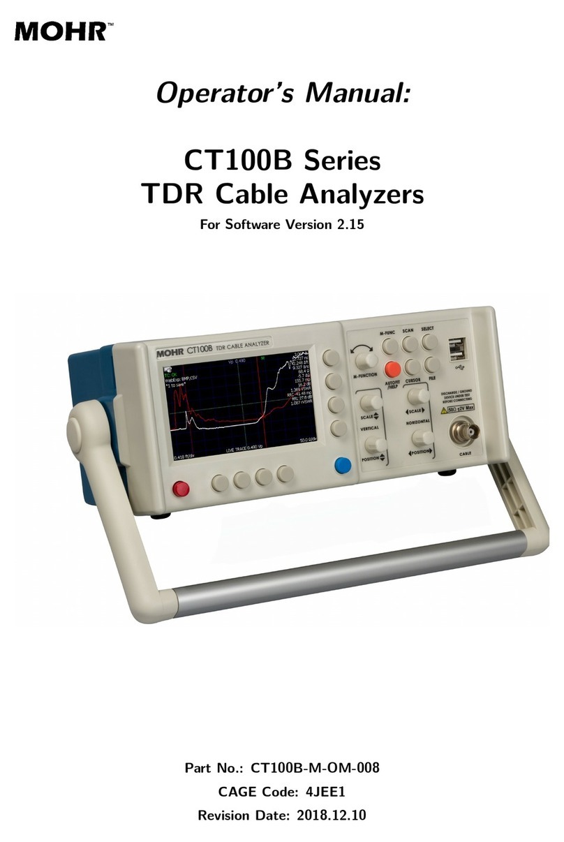
Mohr CT100B Series User manual

Operator’s Manual:
CT100B Series
TDR Cable Analyzers
For Software Version 2.24.5
Part No.: CT100B-M-OM-012
CAGE Code: 4JEE1
Revision Date: 2023.03.07


Copyright Notice
Copyright ©2008-2023 MOHR Test and Measurement LLC (MOHR). All rights reserved.
Reproduction of this manual in print and electronic form is authorized for U.S. Government
purposes only. This manual may not be reproduced, distributed, transmitted, displayed, published,
or broadcast in any form or medium by any other party without written permission from MOHR.
MOHR products are covered by U.S. and foreign patents, issued and pending. Information in this
publication supersedes all previously published material. MOHR reserves the right to change
product specifications or pricing at any time without notice.
This manual contains trademarks and material copyrighted or patented by MOHR and other third
parties. All marks, copyrights, trade secrets, and patents should be considered to be the property
of their respective owners and all rights are reserved. Nothing contained herein shall be construed
by implication, estoppels, or otherwise as granting to the user a license under any copyright,
trademark, patent, or other intellectual property right of MOHR or any third party. Statutory
notice contained herein represents trademark status in the United States.
MOHR Test and Measurement LLC, 2105 Henderson Loop, Richland, WA 99354 USA
CT100B TDR Cable Analyzers Operator’s Manual i


Manual Updates
We at MOHR are always working to improve the written materials we offer to our valued
customers. Since our last printing, there may have been minor updates to this manual.
To view our most recent manual revision, open the accompanying CT Viewer 2 DVD, or visit us
online at www.mohrtm.com. (Please click on Products →CT100 →Downloads.)
Date Generated 2023.03.07
CT100B TDR Cable Analyzers Operator’s Manual iii


Warranty
Purchase and/or use of this product signifies your agreement to the terms of this Warranty.
MOHR Test and Measurement LLC (MOHR) warrants that this product will be free from defects
in materials and workmanship for a period of one (1) year from the date of shipment unless
otherwise stated in writing by MOHR. If any such product proves defective during this warranty
period, MOHR, at its option, will either repair the defective product without charge for parts and
labor, or will provide a replacement in exchange for the defective product. MOHR’s liability and
Buyer’s remedies under this Warranty shall be limited solely to repair, replacement, or credit.
In order to obtain service under this Warranty, customers must notify MOHR of the defect before
the expiration of the warranty period and make suitable arrangements for the performance of
service. Customers shall be responsible for packaging and shipping the defective product to MOHR
with shipping charges prepaid. Customers shall be responsible for paying all return shipping
charges, duties, taxes, and other charges for units returned to any location. Customers shall be
responsible for removing and reinstalling the equipment and for any decontamination procedures
that may be necessary in preparation for shipment.
THIS WARRANTY IS EXCLUSIVE AND IN LIEU OF ANY OTHER WARRANTIES,
EXPRESSED OR IMPLIED, INCLUDING BUT NOT LIMITED TO, ANY IMPLIED
WARRANTY OF MERCHANTABILITY OR FITNESS FOR A PARTICULAR PURPOSE.
MOHR SHALL NOT BE LIABLE UNDER ANY CIRCUMSTANCES FOR CONSEQUENTIAL
OR INCIDENTAL DAMAGES, INCLUDING BUT NOT LIMITED TO LABOR COSTS OR
LOSS OF PROFITS, DAMAGE TO PERSONS OR PROPERTY ARISING IN CONNECTION
WITH THE USE OF OR INABILITY TO USE PRODUCTS PURCHASED FROM MOHR.
Specific limitations of this Warranty:
This Warranty only applies to normal and reasonable use of this product. Damage to
this product resulting from improper use, the determination of which is solely at the
discretion of MOHR, is specifically excluded from this Warranty.
Any electrical damage to this product resulting from connection of a cable or device
carrying a static electrical charge to the front panel BNC connector or SMA
connector without first properly grounding the conducting elements of the cable or
device is specifically excluded from this Warranty.
Any electrical damage to this product resulting from connection of a cable or device
carrying an electrical signal or other non-zero electrical potential relative to earth
ground to the front panel BNC connector or SMA connector is specifically excluded
from this Warranty.
CT100B TDR Cable Analyzers Operator’s Manual v


Contacting MOHR
Phone
+1-888-852-0408
Mail
MOHR Test and Measurement LLC
2105 Henderson Loop
Richland, WA 99354
USA
Email
Sales: [email protected]
Web
www.mohrtm.com
CT100B TDR Cable Analyzers Operator’s Manual vii


Contents
Copyright Notice i
Manual Updates iii
Warranty v
Contacting MOHR vii
Contents ix
List of Figures xiii
List of Tables xv
1. General Information 1
1.1. Product Description . . . . . . . . 1
1.2. Power Requirements . . . . . . . . 1
1.3. Options and Accessories . . . . . . 1
1.4. Unpacking and Initial Inspection . 2
1.5. Repacking for Shipment . . . . . . 2
2. Safety Summary 3
2.1. Terms in the Manual . . . . . . . . 3
2.2. Terms on the CT100B . . . . . . . 3
2.2.1. DANGER . . . . . . . . . . 3
2.2.2. WARNING . . . . . . . . . 3
2.2.3. CAUTION . . . . . . . . . 3
2.3. Symbols in the Manual . . . . . . . 4
2.4. Symbols on the CT100B . . . . . . 4
2.5. Static Charge . . . . . . . . . . . . 4
2.6. Fuses................. 5
2.7. AC Power Source . . . . . . . . . . 5
2.8. Grounding the CT100B . . . . . . 6
2.9. Danger Arising From Loss of Ground 6
2.10. Explosive Atmospheres . . . . . . . 6
2.11. Do Not Remove Covers or Panels . 7
2.12. Connecting Cables to the Test Port 7
2.13. Battery Replacement and Disposal 7
3. Getting Started 9
3.1. Handling . . . . . . . . . . . . . . . 9
3.2. Powering the CT100B . . . . . . . 9
3.2.1. Caring for the Battery . . . 10
3.2.2. Charging and Power Status 10
3.2.3. Batteries and Long-Term
Storage . . . . . . . . . . . 10
3.2.4. Low Battery . . . . . . . . 10
3.3. Labels ................ 11
3.3.1. Nameplate . . . . . . . . . 11
3.3.2. Discharge Warning Label . 11
3.4. License Codes . . . . . . . . . . . . 11
3.5. Preparing to Use the CT100B . . . 12
3.6. Front Panel Controls and Connec-
tors ................. 12
3.7. Rear Panel Connectors and Switches 13
3.8. Keyboard Alternate Controls . . . 14
3.9. Menu Selections and Function
Buttons ............... 15
3.9.1. M-FUNC Button . . . . . . 15
3.9.2. SCAN Button and Menu . 15
3.9.3. SELECT Button . . . . . . 19
3.9.4. AUTOFIT/HELP Button
and Menu . . . . . . . . . . 19
3.9.5. CURSOR Button . . . . . . 20
3.9.6. FILE Button and Menu . . 20
3.9.7. “Blue” MENU Button and
Top-Level Menu . . . . . . 21
3.10. Setting up the CT100B . . . . . . 31
3.10.1. Navigating Dialog Boxes . . 31
3.10.2. Display Features . . . . . . 32
3.10.3. Setting Date and Time . . . 33
3.10.4. Temperature Correction . . 34
3.11. Cable Length Settings . . . . . . . 34
3.12. Sample Resolution . . . . . . . . . 34
3.13. Measurement Settings . . . . . . . 36
3.13.1. Horizontal Units . . . . . . 36
3.13.2. Vertical Units . . . . . . . . 36
3.13.3. Relative Reflection Coeffi-
cient (RRC) Method . . . . 37
CT100B TDR Cable Analyzers Operator’s Manual ix

Contents
4. Operating Instructions 39
4.1. Connecting to the Cable or
Device-Under-Test (DUT) . . . . . 39
4.2. Common Types of TDR Cable Faults 40
4.3. Change Velocity of Propagation (Vp) 42
4.3.1. Fine Vp Control . . . . . . 42
4.4. Find an Unknown Velocity of
Propagation (Vp) . . . . . . . . . . 42
4.5. Cable Type Library . . . . . . . . 45
4.5.1. Load a Cable Type’s Vp . . 45
4.5.2. Custom Cable Types . . . . 45
4.6. Smooth Settings . . . . . . . . . . 45
4.7. Distance-to-Fault . . . . . . . . . . 46
4.7.1. Measure Distance-to-Fault
(DTF)............ 46
4.7.2. Relative Distance and
DTF Measurements . . . . 48
4.7.3. Multi-Segment Cable DTF
Measurements . . . . . . . 51
4.8. Scan a Cable . . . . . . . . . . . . 53
4.9. Working With Traces . . . . . . . 54
4.9.1. Select a Trace . . . . . . . . 54
4.9.2. Annotate a Trace . . . . . . 56
4.9.3. Store a Trace . . . . . . . . 60
4.9.4. Load a Trace (Cable
Records) . . . . . . . . . . . 62
4.9.5. Transfer and Delete Traces 63
4.10. User Configurations . . . . . . . . 64
4.10.1. Save Configurations . . . . 65
4.10.2. Load Configurations . . . . 65
4.11. Mask Testing . . . . . . . . . . . . 65
4.11.1. Storing a Mask . . . . . . . 67
4.11.2. Loading a Mask . . . . . . 67
4.11.3. Saving and Loading a
Mask as Part of a Con-
figuration . . . . . . . . . . 67
4.11.4. Exporting/Importing a Mask 67
4.11.5. Deleting a Mask . . . . . . 68
4.12. Envelope Plot (Transient/Intermittent
Fault Detection) . . . . . . . . . . 68
4.13. Improving Measurements . . . . . 71
4.13.1. Vertical Reference (Vert.
Ref.) Calibration . . . . . . 71
4.13.2. Cable Resistive Loss Cor-
rection............ 72
4.14. Take a Screenshot . . . . . . . . . 73
4.15. Web Server . . . . . . . . . . . . . 74
4.16. Remote Control . . . . . . . . . . . 75
5. Math Functions 77
5.1. Difference (Subtraction) Traces . . 77
5.2. First Derivative (Slope) Traces . . 78
5.2.1. Second and Higher Order
Derivative Traces . . . . . . 79
5.3. Fast Fourier Transform (FFT)
Traces ................ 79
5.4. Return Loss (S11) Traces . . . . . . 80
5.5. Return Loss (S11) Options . . . . . 81
5.5.1. Return Loss (S11) Pre-Filter 82
5.5.2. Return Loss (S11) Post-Filter 82
5.5.3. Return Loss (S11) Phase
Correction . . . . . . . . . . 82
5.5.4. Time-Domain Gating, or
Return Loss (S11) Between
Cursors . . . . . . . . . . . 83
5.5.5. Return Loss (S11) Calibra-
tion Standards . . . . . . . 84
5.5.6. Other Return Loss (S11)
Options . . . . . . . . . . . 85
5.6. Improving S-Parameter Measure-
ments ................ 85
5.7. Normalized TDR Traces . . . . . . 86
5.8. Layer-Peeling (Dynamic Deconvo-
lution) Traces . . . . . . . . . . . . 87
5.9. Smith Charts . . . . . . . . . . . . 88
6. CT Viewer 91
6.1. Transferring Saved Traces to a
Computer . . . . . . . . . . . . . . 91
6.1.1. Send Saved Traces with a
Thumb Drive . . . . . . . . 91
6.1.2. Send Saved Traces over USB 92
6.1.3. Send Saved Traces Using
Ethernet . . . . . . . . . . . 92
6.2. Using Remote Control . . . . . . . 94
6.2.1. Record and Playback Real-
Time TDR Trace Movies . 94
7. TDR Measurement Theory 95
7.1. Time-Domain Reflectometry (TDR) 95
7.2. Reflection Coefficients . . . . . . . 95
7.3. Common Types of TDR Cable Faults 96
7.4. Velocity of Propagation (VoP, Vp) 99
7.5. Distance-to-Fault (DTF) and Ca-
bleLength.............. 99
7.6. Impedance . . . . . . . . . . . . . . 99
7.7. Return Loss . . . . . . . . . . . . . 101
xCT100B TDR Cable Analyzers Operator’s Manual

Contents
7.8. VSWR................102
7.9. Rise Time and Spatial Resolution . 103
7.10. Timebase/Cursor/Horizontal Res-
olution................104
7.11. Frequency-Domain Measurements . 105
7.11.1. Scattering Parameters . . . 105
7.11.2. Return Loss (S11) . . . . . 106
7.11.3. Insertion Loss (S21) . . . . 106
7.11.4. Cable Loss (S21) . . . . . . 106
7.12. Normalized TDR Traces . . . . . . 107
7.13. Layer Peeling/Dynamic Deconvo-
lution ................107
7.14. Smith Charts . . . . . . . . . . . . 108
A. Specifications 111
A.1. Electrical Specifications . . . . . . 111
A.2. Environmental Specifications . . . 113
A.3. Mechanical Specifications . . . . . 113
A.4. Certifications and Compliances . . 113
B. Operator Performance Checks 115
B.1. General Information . . . . . . . . 115
B.2. Required Equipment . . . . . . . . 115
B.3. Getting Ready . . . . . . . . . . . 116
B.4. Operator Performance Checks . . . 116
C. Options and Accessories 121
C.1. Options . . . . . . . . . . . . . . . 121
C.2. Accessories . . . . . . . . . . . . . 121
C.2.1. Standard BNC Accessories
– CT100B (BNC) . . . . . 121
C.2.2. Standard SMA Accessories
– CT100B (SMA), CT100HF122
C.2.3. Optional Accessories . . . . 122
D. Vpof Common Cables 123
D.1. Cable Types . . . . . . . . . . . . . 123
D.2. Dielectric Material . . . . . . . . . 123
D.3. RG Standards . . . . . . . . . . . . 124
D.4. MIL-C-17 Standards . . . . . . . . 124
D.5. Commercial Designations . . . . . 125
D.6. Twisted Pair . . . . . . . . . . . . 125
E. Maintenance and Service Instructions 127
E.1. Cleaning and Lubrication . . . . . 127
E.2. Cleaning and Lubrication Interval 127
E.3. Battery Removal/Replacement . . 127
E.4. Calibration and Calibration Interval128
E.5. Install CT100B License . . . . . . 128
E.6. Clean Storage . . . . . . . . . . . . 128
F. Operator Troubleshooting 129
F.1. General Information . . . . . . . . 129
F.2. Power On Test . . . . . . . . . . . 129
F.3. Functional Block Diagram and
Troubleshooting Flowcharts . . . . 129
F.4. Parts List . . . . . . . . . . . . . . 140
Glossary 141
Index 147
CT100B TDR Cable Analyzers Operator’s Manual xi


List of Figures
3.1. Example nameplate label found on back of a CT100B . . . . . . . . . . . . . . . . . 11
3.2. Diagram of the CT100B front panel . . . . . . . . . . . . . . . . . . . . . . . . . . . 12
3.3. Diagram of the rear panel of the CT100B/CT100HF . . . . . . . . . . . . . . . . . . 14
3.4. Keyboard controls for front panel buttons and knobs . . . . . . . . . . . . . . . . . . 15
3.5. TheResetOptionsmenu.................................. 20
3.6. The two versions of the Main menu . . . . . . . . . . . . . . . . . . . . . . . . . . . . 22
3.7. Example of a dialog box with entries to be filled in . . . . . . . . . . . . . . . . . . . 31
3.8. Example of a dialog box with a scrollable list of items . . . . . . . . . . . . . . . . . 32
3.9. Screenshot showing typical features of the CT100B . . . . . . . . . . . . . . . . . . . 33
3.10. A small fault in a long cable . . . . . . . . . . . . . . . . . . . . . . . . . . . . . . . . 35
3.11. Example trace with impedance (ohms) as vertical unit . . . . . . . . . . . . . . . . . 36
4.1. Clip lead adapter and controlled impedance adapter . . . . . . . . . . . . . . . . . . 40
4.2. Anopenfault........................................ 40
4.3. Ashortfault ........................................ 41
4.4. A scan of an SMA connector . . . . . . . . . . . . . . . . . . . . . . . . . . . . . . . 41
4.5. Screenshot showing AUTOFIT result . . . . . . . . . . . . . . . . . . . . . . . . . . . 43
4.6. Use of HORIZONTAL SCALE knob to improve Vp accuracy . . . . . . . . . . . . . 44
4.7. FinalVpofthecable.................................... 44
4.8. Smoothed vs. unsmoothed traces at very small vertical scales . . . . . . . . . . . . . 46
4.9. AUTOFIT cable. The cable termination is a short . . . . . . . . . . . . . . . . . . . 47
4.10. Vertical scale used to emphasize cable fault . . . . . . . . . . . . . . . . . . . . . . . 47
4.11. A zoomed in view of the cable fault . . . . . . . . . . . . . . . . . . . . . . . . . . . . 48
4.12. Relative distance measurement between two impedance “faults” . . . . . . . . . . . . 49
4.13. The Set/Clear Zero Offset button on the Display menu . . . . . . . . . . . . . . . . . 50
4.14.TheZeroOffsetmenu ................................... 50
4.15. Zero Offset applied to a trace . . . . . . . . . . . . . . . . . . . . . . . . . . . . . . . 51
4.16. Multi-segment cable segment with Vp of 0.400 . . . . . . . . . . . . . . . . . . . . . . 52
4.17. Multi-segment cable segment with Vp of 0.850 . . . . . . . . . . . . . . . . . . . . . . 52
4.18. Scan of a portion of a cable, zoomed-in vertically . . . . . . . . . . . . . . . . . . . . 53
4.19. Scan progress display with Cancel button . . . . . . . . . . . . . . . . . . . . . . . . 54
4.20.Selectingthelivetrace................................... 55
4.21. Selecting a scanned trace . . . . . . . . . . . . . . . . . . . . . . . . . . . . . . . . . 55
4.22. Selecting a difference trace . . . . . . . . . . . . . . . . . . . . . . . . . . . . . . . . . 56
4.23. The Annotations selection in the Scan menu . . . . . . . . . . . . . . . . . . . . . . . 57
4.24.TheAnnotationsmenu................................... 57
4.25. Use Set Start Point to annotate a specific point on a trace . . . . . . . . . . . . . . . 58
4.26. Use Set Start Point and Set End Point to annotate a range of points on a trace . . . 58
4.27.Theannotationslist .................................... 59
4.28. Annotations appear as arrows on the trace . . . . . . . . . . . . . . . . . . . . . . . . 59
CT100B TDR Cable Analyzers Operator’s Manual xiii

List of Figures
4.29. The name of the currently selected annotation is displayed in the multifunction indicator 60
4.30. Using the on-screen keyboard . . . . . . . . . . . . . . . . . . . . . . . . . . . . . . . 61
4.31. The save trace default dialog box . . . . . . . . . . . . . . . . . . . . . . . . . . . . . 62
4.32.Loadingatrace....................................... 63
4.33. A trace that passes the mask test . . . . . . . . . . . . . . . . . . . . . . . . . . . . . 66
4.34. A trace that fails the mask test . . . . . . . . . . . . . . . . . . . . . . . . . . . . . . 66
4.35. Envelope Plot with Fill Mode . . . . . . . . . . . . . . . . . . . . . . . . . . . . . . . 69
4.36. Envelope Plot with Frequency Density display . . . . . . . . . . . . . . . . . . . . . . 70
4.37. Envelope Plot with Fill Mode, showing range of impedance values . . . . . . . . . . 70
4.38. Resistive cable loss correction, before . . . . . . . . . . . . . . . . . . . . . . . . . . . 73
4.39. Resistive cable loss correction, after . . . . . . . . . . . . . . . . . . . . . . . . . . . . 73
4.40.Webserverwebpage.................................... 74
4.41. The live control display on the CT100B web page . . . . . . . . . . . . . . . . . . . . 75
5.1. Differencetrace....................................... 78
5.2. Firstderivativetrace.................................... 79
5.3. FFTtrace.......................................... 80
5.4. S11 returnlossplot..................................... 81
5.5. S11 between cursors bracketing an adapter on the TDR trace . . . . . . . . . . . . . 83
5.6. S11 between cursors with tightened connector . . . . . . . . . . . . . . . . . . . . . . 84
5.7. S11 between cursors with loosened connector . . . . . . . . . . . . . . . . . . . . . . . 84
5.8. Using a phase stable cable to improve S-parameter measurements . . . . . . . . . . . 86
5.9. Normalized trace showing short fault in a 50 ohm cable . . . . . . . . . . . . . . . . 87
5.10. Example layer-peeling trace . . . . . . . . . . . . . . . . . . . . . . . . . . . . . . . . 88
5.11. Smith chart representation of open fault . . . . . . . . . . . . . . . . . . . . . . . . . 89
5.12. Smith chart representation of short fault . . . . . . . . . . . . . . . . . . . . . . . . . 89
5.13. Smith chart representation of a 50 ohm resistive load . . . . . . . . . . . . . . . . . . 90
5.14. Smith chart of reactive 200 ohm load . . . . . . . . . . . . . . . . . . . . . . . . . . . 90
6.1. Options under the Connect to CT Viewer menu . . . . . . . . . . . . . . . . . . . . . 93
6.2. Manual Connect in the Connect to CT Viewer menu brings up a server menu . . . . 93
7.1. An open cable fault shows an upward step edge at the location of the fault . . . . . 96
7.2. A short cable fault shows a downward step edge at the location of the fault . . . . . 97
7.3. An open cable fault at 824 ft . . . . . . . . . . . . . . . . . . . . . . . . . . . . . . . 97
7.4. Normal SMA female barrel interconnect measuring 52.1 ohms . . . . . . . . . . . . . 98
7.5. Comparison of typical SMA and BNC coaxial cable interconnects . . . . . . . . . . . 98
7.6. Relationship of impedance to reflection coefficient . . . . . . . . . . . . . . . . . . . . 100
7.7. Relationship of return loss to reflection coefficient . . . . . . . . . . . . . . . . . . . . 101
7.8. Relationship of voltage standing wave ratio to reflection coefficient . . . . . . . . . . 102
7.9. Simulated comparison of 90 ps rise time TDR to an 800 ps TDR . . . . . . . . . . . 104
7.10. Comparison of S11 return loss measured by TDR and VNA . . . . . . . . . . . . . . 106
7.11. Layer-peeling scattering diagram . . . . . . . . . . . . . . . . . . . . . . . . . . . . . 108
7.12. Impedance Smith chart relationships . . . . . . . . . . . . . . . . . . . . . . . . . . . 109
xiv CT100B TDR Cable Analyzers Operator’s Manual

List of Tables
3.1. SCANButtonandMenu.................................. 16
3.2. MathMenu ......................................... 17
3.3. FILEButtonandMenu .................................. 20
3.4. MENUButtonandMenus................................. 22
B.1. Required Performance Check Equipment for CT100B . . . . . . . . . . . . . . . . . . 115
B.2. Required Performance Check Equipment for CT100HF and CT100B with SMA Option116
D.1. Vp of Common Dielectric Materials . . . . . . . . . . . . . . . . . . . . . . . . . . . . 123
D.2.VpofRGStandards .................................... 124
D.3.VpofMIL-C-17Standards................................. 124
D.4. Vp of Commercial Designations . . . . . . . . . . . . . . . . . . . . . . . . . . . . . . 125
D.5.VpofTwistedPairs .................................... 125
CT100B TDR Cable Analyzers Operator’s Manual xv


1. General Information
1.1. Product Description
The MOHR CT100B TDR Metallic Cable Analyzer uses a form of closed-circuit radar known as
time-domain reflectometry (TDR) to test cables for defects or “faults”. The instrument applies a
fast rise time broadband step signal to the cable under test and then measures the reflected voltage
at very short time intervals. The resultant TDR trace allows the operator to identify changes in
impedance along the length of the cable indicating the presence of faults such as opens, shorts,
kinks, defects in the shield or conductor, foreign substances such as water, and thermal damage,
among others.
The CT100B provides sophisticated signal-processing software that lets users analyze the
frequency-domain characteristics of the TDR trace, replacing a handheld vector network analyzer
(VNA) or frequency-domain reflectometer (FDR) for many applications. With the CT100B TDR
Cable Analyzer a user can detect, localize, and characterize almost any cable fault in both the time
and frequency domains.
Please note that with the release of the CT100B, the CT100HF instrument has been updated with
the CT100B hardware, firmware, and software improvements. Any reference to the CT100B in this
manual also applies to the CT100HF unless specifically stated.
1.2. Power Requirements
The CT100B may be operated using either the supplied AC adapter or internal NiMH batteries
(for a minimum six hours operating time, typical use). The internal NiMH battery charges under
AC during normal operation.
The external AC power adapter (pn: CT100-AC-PS) operates on 100-240 VAC at 50-60 Hz and
draws a maximum current of 1.5 A. Use of a grounded AC socket (US 3-prong or EU equivalent) is
essential for safe operation of the CT100B with the included AC power adapter. Review the Safety
Summary section before operating the CT100B.
1.3. Options and Accessories
Options and accessories available for the CT100B are described in Appendix C, Options and
Accessories.
CT100B TDR Cable Analyzers Operator’s Manual 1

1. General Information
1.4. Unpacking and Initial Inspection
Before opening the shipping package containing the CT100B, inspect it for signs of damage. If
there is evidence of damage to the shipping package, notify both the shipping carrier and MOHR.
The shipping container should contain the CT100B and standard accessories, including this
Operator’s Manual, front panel cover, external AC adapter and power cord, soft transit case, and
calibration fixture(s). If the shipping container is intact but there are missing items or if the
CT100B is damaged, defective, or does not meet operational requirements, contact a
MOHR-authorized sales representative.
1.5. Repacking for Shipment
In the event that the CT100B needs to be shipped to a MOHR-authorized service center for repair,
calibration, or other service, contact MOHR for a Return Material Authorization (RMA) number.
Affix a label to the outside of the shipping container indicating:
•RMA number
•name, address, phone, and email of the owner
•name of the MOHR service representative who was contacted regarding the shipment
•serial number of the instrument
•description of the problem with the instrument and/or the desired service or maintenance
Optimally, the original shipping carton and packing material should be used to repack the CT100B
for shipment. Otherwise, the following steps should be taken:
1. Place the CT100B in an electrostatic discharge (ESD) safe bag.
2. Wrap with 3 in. of antistatic bubble wrap or non-movable foam cushioning. DO NOT USE
packaging peanuts.
3. Place in a sturdy cardboard box and fill any additional void with packaging material. DO
NOT USE packaging peanuts.
4. Include any Purchase Orders, Work Orders, or special instructions with shipment.
5. Write the RMA number on outside packaging.
2CT100B TDR Cable Analyzers Operator’s Manual
Other manuals for CT100B Series
1
Table of contents
Other Mohr Measuring Instrument manuals
Popular Measuring Instrument manuals by other brands

Amprobe
Amprobe MO-100 user manual

Integrated Meterting Systems
Integrated Meterting Systems MS120S01 Technical specifications and installation instructions

VOLTCRAFT
VOLTCRAFT VBM-100 operating instructions

Norav Medical
Norav Medical NR-1207-E Installation and operation guide

Galvanic Applied Sciences
Galvanic Applied Sciences ProTech903 Operation manual

Bartec
Bartec Tech500 user guide