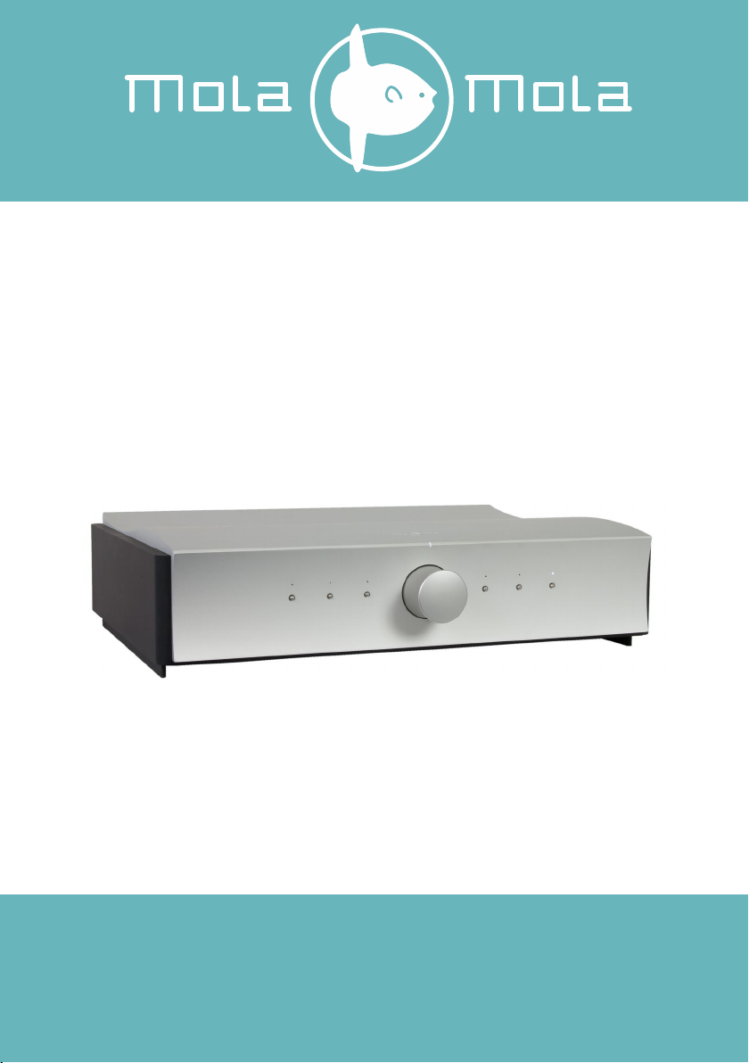
Mola-Mola Kula User manual

Mola Mola
Kattegat 8
9723 JP Groningen
The Netherlands
+31 50 526 4993
info@mola-mola.nl
www.mola-mola.nl
Kula
the integrated amplifier
User’s Manual

Kula
Integrated Amplifier
User’s Manual
R4
Please read this manual before operating the device
Packing list
Your product was shipped with the items checked below. Please verify that you find all
items mentioned in this list before you start setting up:
This Mola Mola product has no user serviceable parts inside. Opening and/or making
changes to the unit by any other than Mola Mola approved service engineers voids the
warranty.
Item
Qty
Shipper’s signature
Integrated Amplifier
1
Power Cord
1
Standard Remote Control Unit
Premium Remote Control Unit
Phono Option (internal)
DAC Option (internal)

Kula
Integrated Amplifier
User’s Manual
R4
Welcome
First off, congratulations! With the purchase of this product you have joined a growing
community of audiophiles who value truthful sound reproduction and who consider neutral
and transparent electronics a cornerstone in this pursuit. We at Mola Mola made it our
primary goal to build electronics capable of passing a signal with no discernible change at
all. Amplifiers make the signal bigger, converters turn the signal from a digital
representation into an analogue one. In all these processes we strive to add nothing and to
remove nothing.
Through our work designing professional audio equipment we have collected extensive
knowledge of how to achieve total freedom from colouration without having to resort to
minimalist circuitry. This allows us to build products that are purist without cutting back
functionality. So we decided that our integrated amplifier should be complete. Very
complete.
The basic Kula Integrated Amplifier has an extremely transparent gain stage and a
programmable routing matrix. The chassis has ample room to fit in optional extras, most
notably a DAC and a phono stage.
The 6 preset buttons are programmable via Bluetooth to access any combination of
channel, processing and routing. In a system with mainly digital sources, the preset buttons
would be programmed to select between them. Vinyl lovers on the other hand might want
to use several buttons to select the same turntable but with different EQ settings to suit
their large collection of historic LP's. All five inputs are switchable between XLR and floating
RCA connections, and all can be assigned as either phono or line.
We wish you a lifetime of musical enjoyment with this product and thank you for your
custom.
Mola Mola Team

Kula
Integrated Amplifier
User’s Manual
R4
Table of contents
Important Safety Instructions ........................................................................................ 1
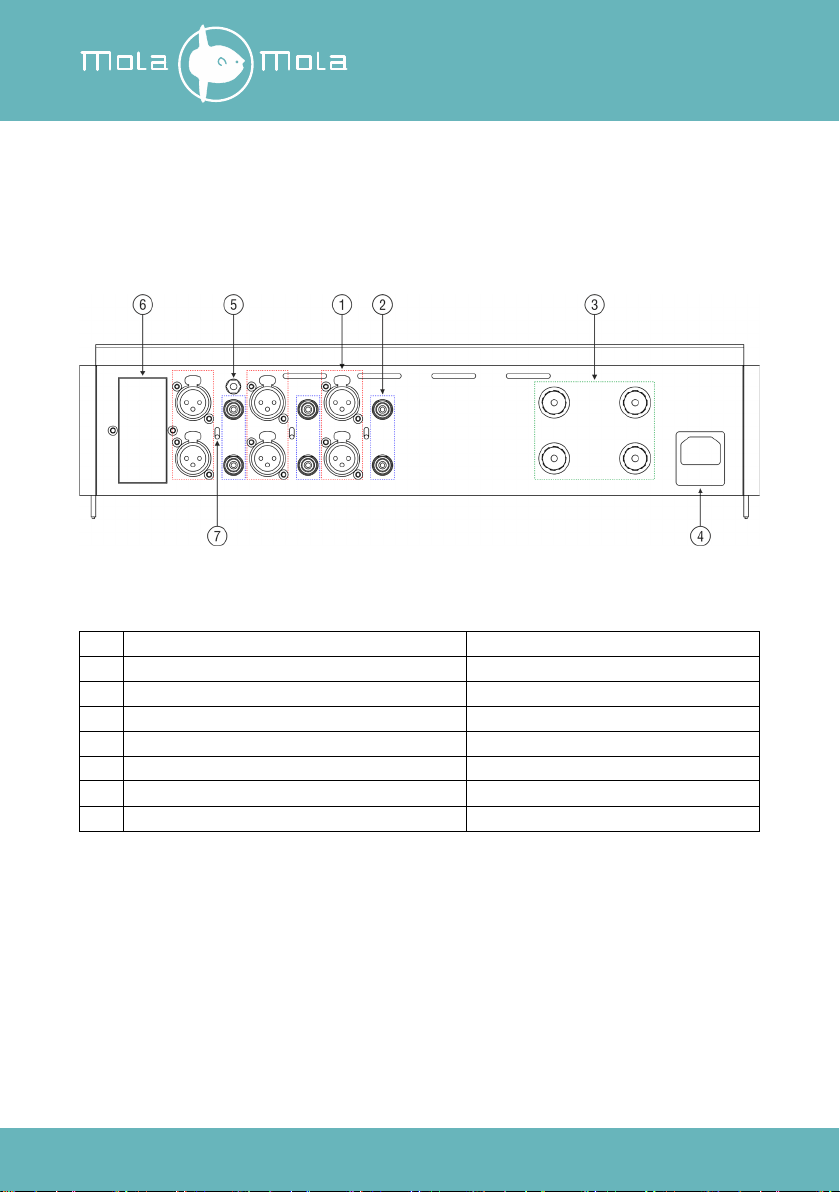
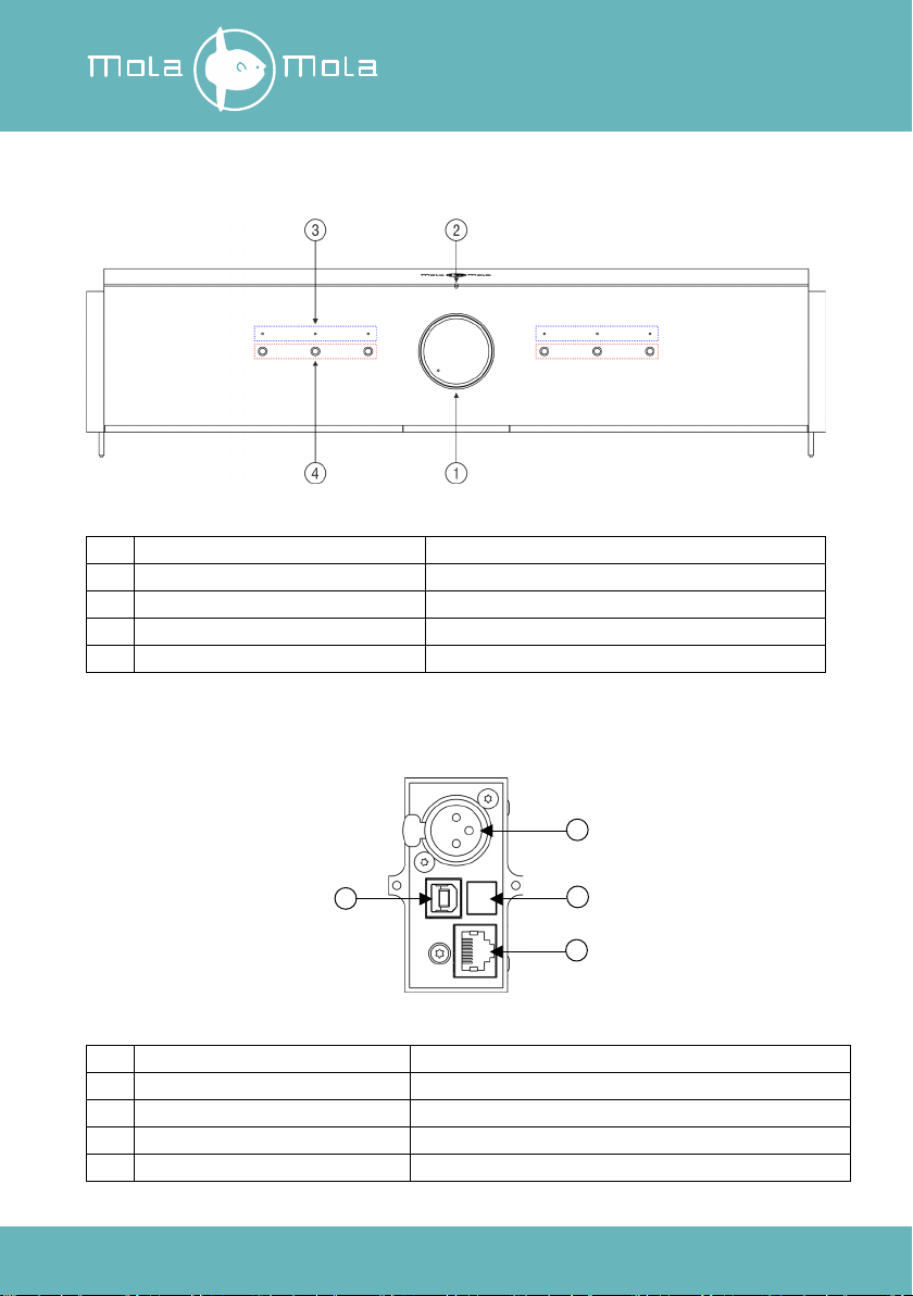
Connections & Controls ................................................................................................ 3
Rear ......................................................................................................................... 3
Front......................................................................................................................... 4
DIGIN module (optional) ............................................................................................ 4
Setting Up .................................................................................................................... 5
Installation ................................................................................................................ 5
Connection ............................................................................................................... 5
Basic operation ............................................................................................................ 7
Factory Preset Mode ................................................................................................. 7
Front Panel Operation ................................................................................................ 7
Premium IR Remote Control Operation....................................................................... 8
Standard IR Remote Control Operation....................................................................... 8
Android®and iOS®.................................................................................................... 8
Advanced Control and Programming ............................................................................. 9
Signal Path ............................................................................................................... 9
Programmability...................................................................................................... 10
The Mola Mola Remote app ........................................................................................ 11
Setting Up and Controlling the Phono Stage ............................................................. 22
Roon.......................................................................................................................... 26
DAC........................................................................................................................ 28
Drivers and Updates................................................................................................ 29
Troubleshooting ......................................................................................................... 30
Audio performance data.............................................................................................. 31
Audio performance data Phono Stage.......................................................................... 32
Audio performance data DAC...................................................................................... 33
Technical data ............................................................................................................ 34
Annex I: RC5 Codes.................................................................................................... 35
Annex II: Standard Remote Control Unit....................................................................... 36
Revision History ......................................................................................................... 37

Kula
Integrated Amplifier
User’s Manual
R4
List of tables
Table 1: Rear panel overview ........................................................................................ 3
Table 2: Front panel overview........................................................................................ 4
Table 3: DIGIN module overview ................................................................................... 4
Table 4: Digital source overview.................................................................................. 28
Table 5: Audio Performance Data ................................................................................ 31
Table 6: Audio performance data Phono Stage ............................................................ 32
Table 7: Audio performance data DAC......................................................................... 33
Table 8: Technical Data .............................................................................................. 34
Table 9: RC5 Codes.................................................................................................... 35
List of figures
Figure 1: Rear panel overview ....................................................................................... 3
Figure 2: Front panel overview....................................................................................... 4
Figure 3: DIGIN module overview .................................................................................. 4
Figure 4: Sketch of the internal signal path..................................................................... 9
Figure 5: Pull down to scan for devices. ...................................................................... 11
Figure 6: Discovered devices. ..................................................................................... 11
Figure 7: Type in new name and click Add device........................................................ 12
Figure 8: The start-up page. ........................................................................................ 12
Figure 9: Swipe left to show disconnect and remove buttons. ...................................... 13
Figure 10: Home Page, Preset 6 is selected................................................................. 14
Figure 11: Preset Page, input 1 is selected. ................................................................. 16
Figure 12: About Page. ............................................................................................... 19
Figure 13: About Page. ............................................................................................... 21
Figure 13: Phono Stage Page. ..................................................................................... 22
Figure 14: List of Phono Stage EQ Curves. .................................................................. 25
Figure 15: The Kula will show up on the Audio settings page in Roon ........................... 26
Figure 16: Fill in Zone Name........................................................................................ 26
Figure 17: Click on Configure Device to go to the Kula webpage................................... 27
Figure 18: The Kula webpage ...................................................................................... 27
Figure 19: Firmware update tool. ................................................................................. 29

Kula
Integrated Amplifier
User’s Manual
R4
- 1 -
Important Safety Instructions
Throughout this document, some aspects of operation that have a potential impact on
safety or reliability are noted with the words “Warning” and “Caution”. Take particular care
reading and understanding these items. Paragraphs marked with “Warning” explain safety
measures required to maintain your personal safety. Paragraphs marked with “Caution”
pertain to danger to the equipment itself or to connected equipment. Please follow these
precautions when using this product:
1. Read these instructions.
2. Keep these instructions.
3. Follow all instructions.
4. Heed all warnings.
5. Install in accordance with the manufacturer’s instructions.
6. Use only attachments or accessories specified by the manufacturer.
7. WARNING: Dangerous voltage is inside this apparatus. Opening is only allowed
by qualified service personnel.
8. WARNING: Do not defeat the safety purpose of the safety earth connection. Use
the provided three-prong power cord to ensure the product is connected to safety
earth. If the provided mains cord does not fit your outlet, consult an electrician for
replacement of the obsolete outlet.
9. Protect the power cord from being walked on or pinched, particularly at plugs,
convenience receptacles, and the point where they exit from the apparatus.
10. Unplug this apparatus during lightning storms or when unused for long periods of
time.
11. WARNING: Do not use this apparatus near water. Do not expose the apparatus to
dripping or splashing. Do not place objects filled with liquids (flower vases, drink
cans, coffee cups, etc) on the apparatus. Do not use this apparatus out of doors.
12. WARNING: Clean only with a dry, soft, lint-free cloth. Do not spray any liquid
cleaner onto the cabinet, as this may lead to dangerous shocks or malfunction.
13. CAUTION: This device runs slightly warm when operated normally. Operate in a
normally ventilated area.

Kula
Integrated Amplifier
User’s Manual
R4
- 2 -
14. CAUTION: Do not install near any heat sources such as radiators, heat registers,
stoves, or other apparatus (including amplifiers) that produce heat. Avoid
exposure to direct sunlight.
15. Use only with a cart, stand, bracket, or table designed for use with audio or music
equipment. In any installation, make sure that injury or damage will not result from
cables pulling on the apparatus and its mounting.
16. Refer all servicing to qualified service personnel. Servicing is required when the
apparatus has been damaged in any way, such as when the power-supply cord
or plug is damaged, liquid has been spilled or objects have fallen into the
apparatus, the apparatus has been exposed to rain or moisture, does not operate
normally, or has been dropped.
17. WARNING: To reduce the risk of fire or electric shock, do not expose this
apparatus to rain or moisture.

Kula
Integrated Amplifier
User’s Manual
R4
- 3 -
Connections & Controls
Rear
Figure 1: Rear panel overview
#
Function
Notes
1 Analogue inputs, balanced 3 stereo pairs
2
Analogue inputs, unbalanced
3 stereo pairs
3
Speaker Outputs, single ended
1 pair of binding posts
4
Mains power input
-
5
Chassis ground terminal
For turntable grounding
6
Option module void cover
-
7
(Un)Balanced toggle switch
One for each input pair
Table 1: Rear panel overview

Kula
Integrated Amplifier
User’s Manual
R4
- 4 -
Front
Figure 2: Front panel overview
#
Function
Notes
1
Volume control knob
With indicator LED
2
Power LED
1 LED, white or dim red
3
Preset indicator LED
6 LEDs, white
4
Presets
6 push buttons
Table 2: Front panel overview
DIGIN module (optional)
Figure 3: DIGIN module overview
#
Function
Notes
1
AES/EBU
2
Optical (Toslink)
3
USB type B
USB audio + firmware updates
4
Network
Only functional when network module is fitted
Table 3: DIGIN module overview
1
2
3
4

Kula
Integrated Amplifier
User’s Manual
R4
- 5 -
Setting Up
Installation
This product relies on free convection of air along the sides and top for cooling. Avoid
placing magazines, books or other objects on top of the product as this acts as thermal
insulation. Installation inside a cupboard is permissible provided at least 30cm (12”) of free
space above the product and 10cm (4”) around the sides is respected. Operation in closer
quarters requires some provision of forced convection (fan) to be installed inside the
cupboard.
Connection
CAUTION: Whenever you are plugging or unplugging cables, make sure that the volume
control is turned fully down. Failure to take this precaution may result in pops or bangs
in the loudspeaker. Use properly shielded interconnects with reliable connectors.
AC Power Input
Connect the supplied power cord to the AC input receptacle on the rear panel. Do not
connect the power cord until all the audio input and output connections have been made.
It is usually best to plug the product directly into a wall outlet. Avoid the use of extension
cords. A heavy duty multi-tap power outlet strip may be used if it and the wall outlet are
rated to handle the total current demanded by the components connected to it.
Your Kula has a universal input power supply, allowing it to operate anywhere from 90V to
240V mains.
If you are going to be away from home for an extended period of time such as a month-
long vacation, it is a sensible precaution to unplug electronic equipment. Do the same as a
precautionary measure during thunderstorms. No amount of surge protection or mains
filtering will save your equipment from a lightning strike in the backyard.
Initialisation procedure
The initialisation procedure only applies when the Kula has the DAC module and network
module fitted. The initialisation procedure will automatically start after the mains power has
been applied will take about one minute. At the start and end of this procedure you might
hear some clicking sounds. During the initialisation procedure the Kula will become visible
in Roon if it is connected to your network. The Kula will also remain visible in Roon during
standby mode. You can power up the Kula during the initialisation procedure and start

Kula
Integrated Amplifier
User’s Manual
R4
- 6 -
listening to analog sources right away. You can start listening to digital sources one minute
after the mains power has been applied.
Input Connections
Your Kula accepts both RCA and XLR type connectors. If your sources have both RCA and
XLR outputs, it is exceedingly likely that using the XLR connection sounds best. Depending
on which you choose, set the toggle switch to the corresponding input.
Output connections
One pair of high grade rhodium-plated binding posts are provided which accepts both
banana and spade connectors.
Grounding Post
Connect any turntable ground wires to the grounding post to minimize the chances of
capacitively induced hum on the phono cartridge from the turntable.

Kula
Integrated Amplifier
User’s Manual
R4
- 7 -
Basic operation
Factory Preset Mode
Your Kula comes factory-programmed as a simple line amplifier. In this mode:
•The leftmost button selects the leftmost source (source 1) and so on and the
rightmost button is used for Roon (if the DAC option is fitted). So for now, think
of the preset button simply as input select buttons.
•XLR/RCA selection is determined by the toggle switches.
Should you wish to return your Kula to its factory-programmed state, you can do so by
holding down the two buttons directly besides the volume control for one second or more.
It makes good sense to do this if this is a device you are loaning for evaluation and it was
sent to you directly by a previous user.
If like most users you only have a handful of line-level sources you can just go ahead and
use the device in this way.
Front Panel Operation
Powering Up
So long as mains power is applied the power LED can be in two states: on or standby. In
standby mode it will light up a dim red (barely visible in daylight, bright red standby LEDs
lighting up the room at night is a pet peeve of the designer). Push any of the 6 buttons to
wake up the amp. The power LED lights up white and the preset you have just pushed will
be engaged (as indicated by the LED above the button).
Selecting Inputs
The preset indicator LED lights up solid when the integrated amplifier is passing signal and
blinks when it is muted. The amp mutes temporarily for a moment after powering up or
after changing presets.
Muting
You can also make your Kula mute by pushing the currently selected preset button. Push
again or change presets to unmute.
Powering Down
You can place the Kula in standby mode by holding any of the 6 buttons until the device
powers down (about 1 second).

Kula
Integrated Amplifier
User’s Manual
R4
- 8 -
Premium IR Remote Control Operation
The group of six buttons on the remote control mirrors the front panel buttons. Pushing any
of them will power the device on and/or engage the associated preset and/or mute the unit.
The top button acts as mute/standby button and does the exact same as the preset buttons
except it does not switch presets. This is mainly useful because the remote control unit
obviously does not have LEDs to indicate which preset is engaged and sometimes you just
want to mute the device regardless of what was playing.
The volume up/down buttons operate as they do anywhere else. The LED on the volume
knob will come on to provide easy visual feedback of the volume setting.
Standard IR Remote Control Operation
The standard-issue RC unit works slightly differently. The button in the middle of the
quadrants turns the Kula on or off (hold 1 second for off). Press this button once for mute
or unmute. Pushing on the left and right quadrants of the ring cycles through the 6 presets.
The top and bottom quadrants control the volume. The two lower buttons are not used.
Android®and iOS®
Your Kula is fitted with a Bluetooth®module to allow access with a mobile device. To use
this feature, install the Mola Mola Remote app from the App Store or Play store.
The home page shows preset buttons and volume control. Other pages are used for
advanced control and programming. They are explained in the Mola Mola remote section.
Powering Up and Down
The stand-by logo in the top left corner acts as power button.
Volume control
Move the slider at the bottom of the home page to change volume. The + and – buttons
can also be used to adjust the volume in small steps. Click on the speaker indicator to mute
or unmute.
Mute
Click on the speaker indicator to mute or unmute. The speaker indicator and volume slider
bar will turn red when muted.

Kula
Integrated Amplifier
User’s Manual
R4
- 9 -
Advanced Control and Programming
The factory preset only operates the most basic features of your integrated amplifier. The
architecture is much more powerful, as the signal path diagram shows.
Signal Path
Figure 4: Sketch of the internal signal path.
Everything that can be switched or changed in the above diagram is under software control:
•XLR/RCA switching
•Source selection
•Routing of any input through the optional phono stage
•Variable loading, gain and EQ of the optional phono stage
•Polarity inversion of left, right or both
•Mono summing

Kula
Integrated Amplifier
User’s Manual
R4
- 10 -
•Volume
•Balance (independent control of left/right volume)
Programmability
Every thinkable combination of routing and processes can be rolled together for direct
access through any of the 6 presets.
Say for instance that you have 2 turntables, each fitted with a different cartridge (most
records sound best with an elliptical or VDH stylus but dynagroove cuts positively require
a conical stylus). You can then assign one preset button to each turntable, each with its
own optimum loading and gain.
Now imagine that some of your most precious historical records are mono, vertically cut
with obviously a non-RIAA curve. You can then assign yet another preset to the same input,
with the same loading and gain but with one channel’s polarity inverted and mono on, and
with the EQ that applies to these records.
As a final example, although the RCA/XLR selection is normally controlled using the toggle
switches, it can be overridden. In the unlikely case that you have 6 sources you can assign
one preset button each to the RCA and XLR pair of one input channel and hence use all 6
buttons to select between 6 sources. Note that crosstalk between RCA and XLR pairs of
one input channel is not as low as between different input channels so you should not co-
locate two sources that you expect to be putting out signal at the same time.

Kula
Integrated Amplifier
User’s Manual
R4
- 11 -
The Mola Mola Remote app
The control app for your Kula is available in the Apple App store and Google Play store. The
app will attempt to contact your Kula and should find it as long as it is within reach and
plugged in. Also ensure that the Bluetooth function of your mobile device is enabled. The
app will auto connect when there is only one Mola Mola device paired with the app. The
app will turn the Kula on during the connection procedure when it is not already turned on.
In case you have multiple Mola Mola devices select the device you wish to operate and
click on Choose device.
First time setup:
1. Pull down to scan for devices (figure 5).
2. Click on the Add button of the device you want add (figure 6).
3. Type in new name and click Add device (figure 7).
4. Connect with device by clicking on Choose device at the bottom of the page
(figure 8).
Figure 5: Pull down to scan for devices.
Figure 6: Discovered devices.

Kula
Integrated Amplifier
User’s Manual
R4
- 12 -
Figure 7: Type in new name and click Add device.
Figure 8: The start-up page.

Kula
Integrated Amplifier
User’s Manual
R4
- 13 -
Swiping a device to the left will allow you to remove the device from the Mola Mola remote
app by clicking on the remove button. If the device is already connected with the app then
an disconnect button is also shown here (figure 9).
Figure 9: Swipe left to show disconnect and remove buttons.

Kula
Integrated Amplifier
User’s Manual
R4
- 14 -
Home Page
The home page is the regular remote control, as outlined in the section about basic
operation. Move the slider at the bottom of the home page to change volume. The + and
– buttons can also be used to adjust the volume in small steps. Click on the speaker
indicator to mute or unmute.
Figure 10: Home Page, Preset 6 is selected.
To program a preset, tap the button of the preset you want to change and click on the edit
preset button in the top right corner.

Kula
Integrated Amplifier
User’s Manual
R4
- 15 -
Status DAC
If a preset with a digital input is selected, the status of the DAC will be shown above the
volume bar on the home page. Input type shows the incoming audio format, PCM or DSD.
Sample rate shows the sample rate of the incoming audio.
Table of contents
Other Mola-Mola Amplifier manuals