75W DALI LED Driver
Montageanleitung / Mounting Instruction
| 26 | 11 | 2021
Austria, 4600 Wels, Europastraße 45, T: +43 7242 698-0, M: office@moltoluce.com
75W DALI LED DRIVER
2 / 4
1
2
SchutzSchutz Überstrom
Over Current
Ja, stellt sich automatisch nach Beseitigung der Fehlerbedingung wieder her.
Yes, recovers automatically after fault condition is removed
Überhitzung
Over Temperature
Ja, stellt sich automatisch nach Beseitigung der Fehlerbedingung wieder her.
Yes, recovers automatically after fault condition is removed
Temperatur im Betrieb
Working Temp. -25°C ~ +45°C
Max. Gehäuse-Temperatur
Max. Case Temp. 88°C (Ta=“45°C“)
Luftfeuchtigkeit im Betrieb
Working Humidity 10% ~ 95% RH nicht kondensierend/non-condensing
Lagerung Temperatur &
Luftfeuchtigkeit
Storage Temp. & Humidity
-40°C ~ +80°C, 10% ~ 95% RH
Sicherheitsstandards
Safety Standards
WWCWUL8750,
CAN/CSA C22.2 NO. 250.13-14,
ENEC EN61347-1, EN61347-2-13 APPROVED
Widerstehende Spannung
Withstand Voltage I/P-O/P: 3.75KVAC
Isolationswiderstand
Isolation Resistance I/P-O/P: 100M Ohms / 500VDC / 25°C / 70% RH
EMC Emission
EMC Emission EN55015, EN61000-3-2, EN61000-3-3
EMC-Störfestigkeit
EMC Immunity EN61547, EN61000-4-2,3,4,5,6,8,11, surge immunity Line-Line 1KV
MTBF
MTBF
186300H, MIL-HDBK-217F @ 230VAC bei Vollast und 25°C
Umgebungstemperatur/at full load and 25°C ambient temperature
Schutz
Protection
Sicherheit & EMC
Safety &EMC
Umfeld
Environment
Sonstiges
Others
• DALI DT8 Dimmbarer LED-Treiber
• In Übereinstimmung mit IEC 62386-101:2014, IEC 62386-102:2014, IEC 62386-207 Ed2, IEC 62386-209:2011
• 2 Kanäle Konstantspannungsausgang, Gesamtausgangsleistung bis zu 75W
• Klasse II-Netzteil, voll isoliertes Kunststoffgehäuse
• Hoher Leistungsfaktor und Wirkungsgrad
• PF > 0,96, Wirkungsgrad > 86%
• Geringe Standby-Leistung < 0,5W
• DALI DT8-Gerät zur Steuerung der Warmweiß- und Kaltweißausgabe über eine einzige DALI-Adresse
• Einstellung der Farbtemperatur gemäß den DALI-Spezifikationen von Device Type 8, Color Type Tc.
• Kompatibel mit universellen DALI-Mastern, die DT8-Befehle unterstützen
• Schutzart IP20, geeignet für LED-Beleuchtungsanwendungen in Innenräumen
• Eingebaute DALI-2 Schnittstelle, DALI DT8 Gerät
• 5 Jahre Garantie
Sicherheit & Warnungen
• Installieren Sie das Gerät NICHT, wenn es unter Spannung steht.
• Setzen Sie das Gerät NICHT der Feuchtigkeit aus
• DALI DT8 Dimmable LED driver
• In compliance with IEC 62386-101:2014, IEC 62386-102:2014, IEC 62386-207 Ed2, IEC 62386-209:2011
• Built-in DALI-2 interface, DALI DT8 device
• 2 channels constant voltage output, total output power up to 75W
• Class II power supply, full isolated plastic case
• High power factor and efficiency
• PF > 0.96, Efficiency > 86%
• Low standby power < 0.5W
• DALI DT8 device to control Warm White and Cool White output via a single DALI address
• Color temperature adjustment according to DALI specifications of Device Type 8, Color Type Tc.
• Compatible with universal DALI masters that support DT8 commands
• IP20 rating, suitable for indoor LED lighting applications
• 5 years warranty
Safety & Warnings
• DO NOT install with power applied to device.
• DO NOT expose the device to moisture.
Bedienung
1. Manuelle Einstellung der DALI-Adresse über die Tasten
1.1 Halten Sie eine der beiden Tasten gedrückt, bis die numerische Digitalanzeige blinkt, und lassen Sie dann die Taste los.
1.2 Klicken Sie einmal auf eine der beiden Tasten, um eine Ziffer auszuwählen, klicken Sie erneut, um die Ziffer zu ändern, bis die
gewünschte DALI-Adresse erscheint. Klicken Sie auf die erste Taste, um die Position „Zehner“ einzustellen, und auf die zweite Taste,
um die Position „Einheiten“ einzustellen. Die Adresse kann von 00~63 eingestellt werden.
1.3 Drücken und halten Sie dann eine der beiden Tasten, bis die numerische Digitalanzeige aufhört zu blinken, um die Einstellung zu
bestätigen.
Hinweis: Die DALI-Adresse kann manuell von 00-63-FF zugewiesen werden, werksseitig ist keine DALI-Adresse für den Dimmer
zugewiesen und auf dem Display erscheint FF. Die Einstellung der DALI-Adresse als FFsetzt den Dimmer auf die Werkeinstellungen
zurück.
2. DALI-Adresse von DALI-Master zugewiesen
Die DALI-Adresse kann auch von einem DALI-Master-Controller automatisch zugewiesen werden, bitte lesen Sie die
Bedienungsanleitungen der kompatiblen DALI-Master für spezifische Vorgänge.
Hinweis: Die Digitalanzeige zeigt AU an, wenn der DALI-Master Adressen vergibt.
3. Sobald eine Adresse ausgewählt ist, haben alle zwei Kanäle die gleiche Adresse. Wenn zum Beispiel der Dimmer 22 adressiert ist,
haben CH1 und CH2 die gleiche Adresse 22.
4. PUSH Dimmer Mode
Während der Verbindung mit einem AC PUSH zeigt die Digitalanzeige „PD“ an, was Push Dimmer Mode bedeutet.
Die Funktionen im Push-Dimmer-Modus sind wie folgt:
4.1. Klicken Sie auf die Taste, um EIN/AUS zu schalten
4.2. Halten Sie die Taste gedrückt, um die Lichtintensität auf das gewünschte Niveau zu erhöhen oder zu verringern, und lassen Sie
sie dann los.
Wiederholen Sie den Vorgang, um die Lichtintensität in die entgegengesetzte Richtung einzustellen.
4.3. Die Speicherfunktion nach dem Ausschalten oder einem Stromausfall ermöglicht es dem Gerät, sich den Status vor dem
Ausschalten zu merken.
Operation
1. Set DALI Address Manually Via Buttons
1.1 Press and hold down any of the two buttons until numeric digital display flashes, then release the button.
1.2 Click any of the two buttons once to select a digit, click again to change the digit until the desired DALI address
appears. Click first button to set “tens” position and second button to set “units” position. The address can be set from
00~63.
1.3 Then press and hold down any of the 2 buttons until the numeric digital display stops flashing to confirm the setting.
Note: DALI address can be manually assigned from 00-63-FF, by factory defaults, no DALI address is assigned for the
dimmer, and the display shows FF. Setting DALI address as FFwill reset the dimmer to factory defaults.
2. DALI Address Assigned by DALI Masters
DALI address can also be assigned by DALI Master controller automatically, please refer to user manuals of
compatible DALI Masters for specific operations.
Note: The digital display will show AU when the DALI master is assigning addresses.
3.Once an address is selected, all two channels‘ address will be the same. For example, if the dimmer is
addressed to 22 on the display then CH1 and CH2 will be the same address 22.
4. PUSH Dimmer Mode
While connected with a AC PUSH, the digital display will show “PD” which means Push Dimmer Mode, operations under Push Dimmer
Mode are as follows:
4.1. Click the button to switch ON/OFF
4.2. Press and hold down the button to increase or decrease light intensity to desired level and release it, then repeat the operation
to adjust light intensity to opposite direction.
4.3. Memory function after power off or power failure enables the device to memorize the status before power off while power on again.
75W DALI LED Driver(DT8) 70220048
Function introduction
Important: Read All Instructions Prior to Installation
MTBF
Others
Over Current Yes, recovers automatically after fault condition is removed
Over Temperature
Protection
Yes, recovers automatically after fault condition is removed
Max. Case Temp. 88℃ (Ta=" ")45℃
Working Humidity
Working Temp.
Environment
-25 ~ +45℃ ℃
10% ~ 95% RH non-condensing
Storage Temp.
& Humidity -40 ~ +80 , 10% ~ 95% RH℃ ℃
Withstand Voltage I/P-O/P: 3.75KVAC
Isolation Resistance
Safety Standards
Safety &
EMC I/P-O/P: 100M Ohms / 500VDC / 25℃ / 70% RH
EMC Emission EN55015, EN61000-3-2, EN61000-3-3
EMC Immunity
EN61547, EN61000-4-2,3,4,5,6,8,11, surge immunity Line-Line 1KV
Product Data
Voltage Range 100-277V AC
Power Factor (Typ.)
Efficiency (Typ.)
Frequency Range 50/60Hz
Input
Rated Power max. 75W
Output Max. Current
DC Voltage
Max. 3.12A/ch, ch1+ch2=3.12A
LED Channel 2
Voltage Tolerance ±1%
> 0.99 @ 100VAC, > 0.96 @ 230VAC
Total Harmonic
Distortion
AC Current (Typ.)
Inrush Current (Typ.)
Leakage Current
Standby Power
Consumption
COLD START 2A at 230VAC
THD ≤
15% (@ full load / 230VAC)
0.9A @ 100VAC, 0.39A @ 230VAC, 0.33A@277VAC
< 0.5mA /230VAC
< 0.5W
86% @ 230VAC full load
Control
Dimming Interface
Dimming Range
Dimming Method
Dimming Curve
0.1%-100%
DALI DT8 (DALI consumption<2mA)/Push
Pulse Width Modulation
Logarithmic
• DO NOT install with power applied to the device.
• DO NOT expose the device to moisture.
Safety & Warnings
Operation
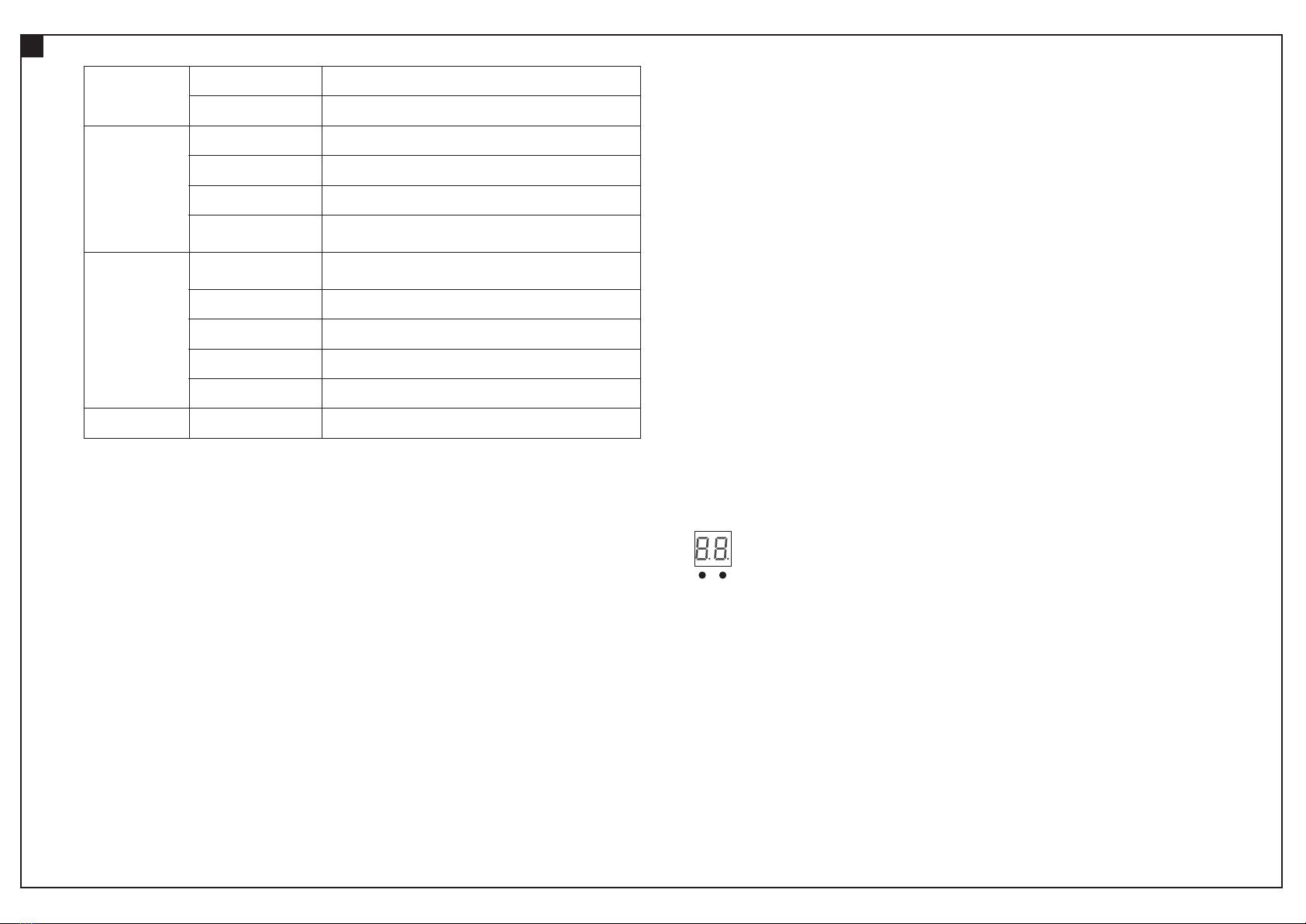
1.1 Press and hold down any of the two buttons until numeric digital display flashes, then release
the button.
1.2 Click any of the two buttons once to select a digit, click again to change the digit until the
desired DALI address appears. Click first button to set “tens” position and second button to set
“units” position. The address can be set from 00~63.
1.3 Then press and hold down any of the 2 buttons until the numeric digital display stops flashing
to confirm the setting.
0-6 0-9
1. Set DALI Address Manually Via Buttons
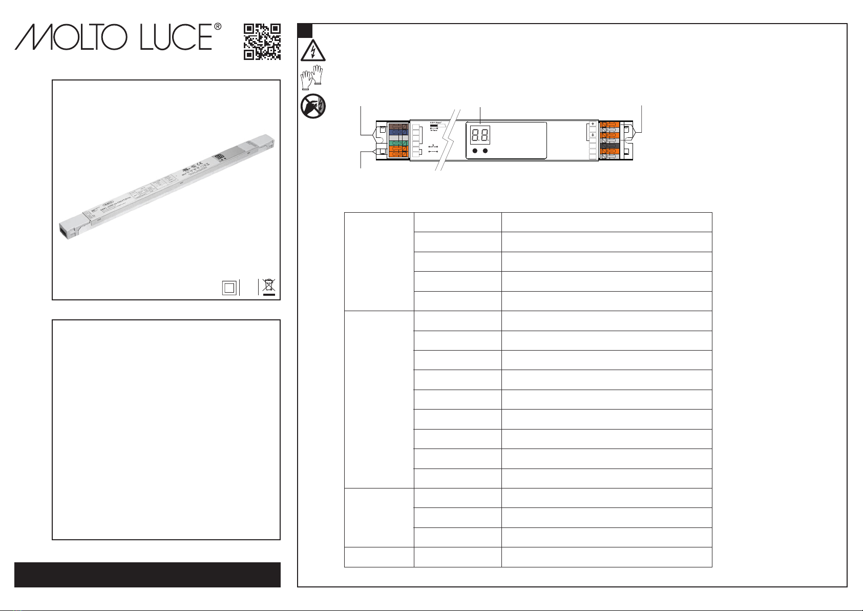
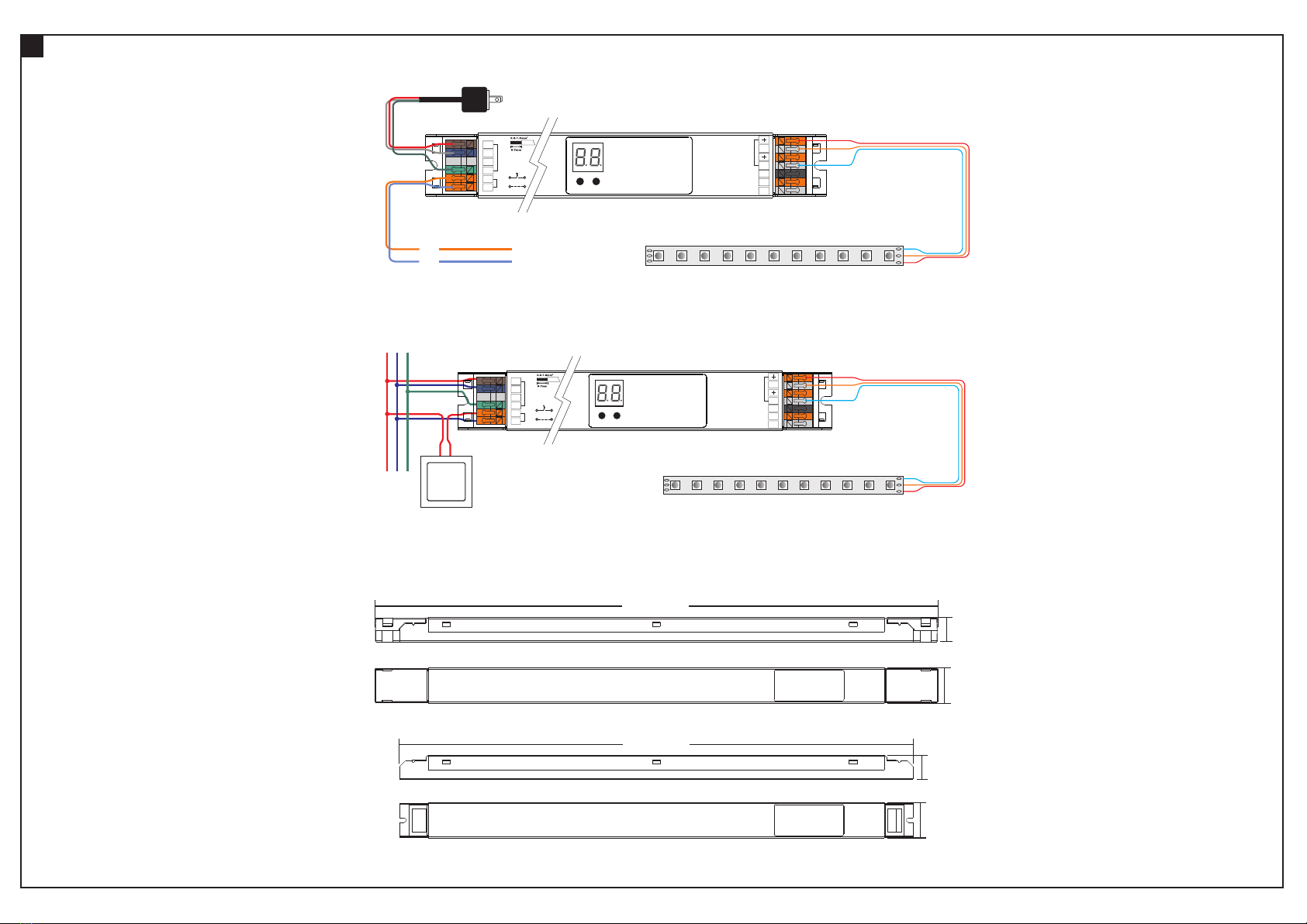
24V DC
LED
OUTPUT
• DALI DT8 Dimmable LED driver
• 2 channels constant voltage output, total output power up to 75W
• Class Ⅱ power supply, full isolated plastic case
• High power factor and efficiency
• PF > 0.96, Efficiency > 86%
• Low standby power < 0.5W
• DALI DT8 device to control Warm White and Cool White output via a single DALI address
• Color temperature adjustment according to DALI specifications of Device Type 8, Color Type Tc.
• Compatible with universal DALI masters that support DT8 commands
• IP20 rating, suitable for indoor LED lighting applications
• In compliance with IEC 62386-101:2014, IEC 62386-102:2014, IEC 62386-207 Ed2, IEC 62386-209:2011
• Built-in DALI-2 interface, DALI DT8 device
• 5 years warranty
WW-
CW-
UL8750, CAN/CSA C22.2 No. 250.13-14,
ENEC EN61347-1, EN61347-2-13 approved
AC 100-277V input
N
L
FG
AC IN PUT
DA
DA
DAL I INPUT
DALI/Push Signal Input
0-6 0-9
Digital display 2 channels LED output
NC
NC
NC
Note: DALI address can be manually assigned from 00-63-FF, by factory defaults, no DALI address is
assigned for the dimmer, and the display shows . Setting DALI address as will reset the dimmer
to factory defaults.
2
186300H, @ 230VAC at full load and 25℃
ambient temperature
MIL-HDBK-217F
PUSH D IM
L
N
DA
DA