Monaco Food Service Venezia1-110V Quick start guide

Monaco Food Service Operational Manual
Italia EspressoMachine
Venezia
1-110V,
Venezia
1-220V,
Venezia
2-220V,
Venezia
3-220V
Model VENEZIA2-220V
Thank you for purchasing this quality espresso machine. For your safety and the safety of others,
read all warnings and the operator manual before installing or using the product. Properly instruct
all operators. Keep training records. For future reference, record serial number here:
Monaco Food Service
10963 Bal Harbor Dr., Boca Raton, FL 33498 USA
Phone:
Toll Free:
Fax: 502.425.4664
Web:
Email:
Table of Contents
Safety Information.................2 Cleaning. ....................... 8
Specifications...........................3 Adjustments...................10
Overview..................................4 Draining ......................... 11
Installation...............................6 Troubleshooting............. 11
Programming ..........................6 Parts Diagram................12
Operation..............................7 Wiring Diagram. ..........25
© 2021 Monaco Food Service
Printed in Taiwan

Safety Information
Important Safety Information
This is the safety alert symbol. It is used to alert you to potential personal injury hazards. Obey all safety
messages that follow this symbol to avoid possible injury or death.
For your safety and the safety of others, read all warnings and the operator manual before installing
or using the product.
DANGER:
This term warns the user of imminent hazard that will result in serious injury or death.
WARNING:
This term refers to a potential hazard or unsafe practice, which could result in serious
injury or death.
CAUTION:
This term refers to a potential hazard or unsafe practice, which could result in minor or
moderate injury.
NOTICE:
This term refers to information that needs special attention or must be fully understood.
WARNING
To reduce risk of electrical shock, do not remove or open cover. No user-serviceable parts inside.
Repair should be done by authorized service personnel only.
The appliance is not intended for outdoor use. Do not expose to rain or direct sunlight.
Do not clean with pressurized water or use in an area where pressurized water may be used.
Cleaning and maintenance shall be made only by properly trained persons with supervision.
This appliance is not intended for use by persons with reduced physical, sensory, or mental capabilities,
or lack of experience and knowledge, unless they have been given supervision or instruction concerning
use of the appliance by a person responsible for their safety.
Children should be supervised to ensure that they do not play with the appliance.
Do not alter or deform the power cord or plug in any way! Altering or deforming the plug may cause
electrical shock, damage unit, and will void warranty.
To reduce risk of explosion or fire, do not use near combustibles.
CAUTION
For safe and proper operation, the appliance must be placed in a stable, vertical position.
To reduce risk of serious burns or scalding, do not place hand or other body parts under dispenser while
product is brewing.
Always unplug unit from power supply before servicing.
Surfaces are hot and can cause burns. Use caution especially in the areas of the steam wand, hot water
wand, and brewing group.
Packaging material, including plastic bag and Styrofoam, can be dangerous and should be kept out of
reach of children.
To reduce risk of electrical shock, do not touch machine with wet hands or feet.
NOTICE
Observe machine voltage configuration. Do not apply improper voltage to machine or damage to
machine may
occur. For use on individual dedicated branch circuit only. Do not use extension cord.
Follow national and local electrical codes.
Do not use the machine and turn off the power during water outage.
This equipment must be installed in compliance with applicable Federal, State, and/or Local
plumbing codes
having jurisdiction. This product requires an approved back flow prevention water device, such as a
double
check valve, to be installed between the machine and the water supply.
Please follow maintenance and cleaning instructions specified in this manual to ensure the best
operation
efficiency of machine.
Italia Espresso Machine Monaco Food Service ® ® 2

Specifications
Identification Label
Every machine has an identification label placed on the front of the machine as illustrated below. The
label includes information of model number, voltage, serial number, wattage, and its certificate. Do not
remove this label.
Rough-In Drawing
Italia Espresso Machine Monaco Food Service ® ® 3
Figure A
Figure B

GB Series Cecilware® 2
Specifications (continued)
Specification Table
Model
Group Heads
Boiler Capacity
Electrical
VENEZIA1-110
1 Group
6.34 quarts
/
6 L
110/120V / 1Ph / 50/60 Hz / 18 A / 2,000W
VENEZIA1-220
1 Group
6.34 quarts
/
6 L
220/240V / 1Ph / 50/60 Hz / 9 A / 2,500W
VENEZIA2-220
2 Groups
13 quarts
/
12 L
220/240V / 1Ph / 50/60 Hz / 21A / 4700W
VENEZIA3-220
3 Groups
19.02 quarts
/
18 L
220/240V / 1Ph / 50/60 Hz / 30 A / 6500W
Side Clearance required - 4" (10.2 cm)
Rear Clearance required - 4" (10.2 cm) for water and electrical connections
Water connection size - 3/4" GHT, 1/2" water line required
Water pressure between 1.4~9 bar (138 kPa - 827 kPa). Use regulator if higher pressure.
Overview
VENEZIA1
Figure C
VENEZIA2
Figure D
Italia Espresso Machine Monaco Food Service ® ® 4

Overview continued
VENEZIA3
Figure E
Figure F
Control Panel
Figure G
1 Espresso brewing unit control panel
11 Cup rack
4 Hot water wand
12 Sight glass (Boiler level check window)
5 Steam knob
14 Steam boiler pressure gauge
6 Steam wand
15 Pump pressure gauge
7 Main switch
17 Drain tray
8 Brewing group
18 Leg
9 Porta Filter
20 Hot water knob
Italia Espresso Machine Monaco Food Service ® ® 5
Small double portion
Large double portion

Installation
Unpacking Instructions
Carefully unpack the machine and inspect
immediately for shipping damage. The
packaging may contain unattached parts.
Your machine was shipped in a carton
designed to give it maximum protection in
normal handling. It was thoroughly
inspected before leaving the factory. In case
of damage, contact the shipper, not Monaco
Food Service.
NOTICE:
This equipment must be installed in
compliance with applicable Federal, State, and/or
Local plumbing codes having jurisdiction. This
productrequires an approved back flow prevention
water device, such as a double check valve, to be
installed between the appliance and the water
supply. If a check valve type backflow preventer is
used for water supply protection, a screen of at
least 100 mesh (100 strands per 1.0 in [25 mm])
shall be installed immediately upstream. The
screen shall be accessible and removable for
cleaning or replacement. (Required for NSF
approved water hook- up.)
Incoming pressure should be greater than 20 psi
and not more than 90 psi.
A filtering system is recommended to remove
odors and inhibit lime and scale build up in the
unit.
In areas with extremely hard water, a water
softener must be installed in order to prevent a
malfunctioning of the equipment and in order
not to void the warranty. Unsoftened water will
decompose dissolvable minerals and turn to
limescale after boiling. The limescale will reduce
the machine’s thermal efficiency and machine’s
lifetime.
NOTICE:
Do not use extension cords. Make sure
that the
outlet the unit plugs into is grounded.
Check rating marking on nameplate to be sure
electric lines match voltage, phase, and
amperage requirements of appliance.
Connections
1.
When operating the machine for the first time
or replacing water softener and filtration
system, remove the water inlet tube and allow
it to drain for about one minute in order to get
rid of impurities from the water.
2.
Connect a 1/2" diameter water line to the
water supply connection.
3.
Open the water shut-off valve and check
connections for leaks. DO NOT over-tighten.
Verify water supply.
4.
Connect 18mm diameter drain line to bottom,
center of machine.
5.
Attach appropriate plug to cord. Power source
corresponds to the electrical rating shown on
the serial tag on unit. Plug the CS Espresso
machine into a dedicated power supply outlet.
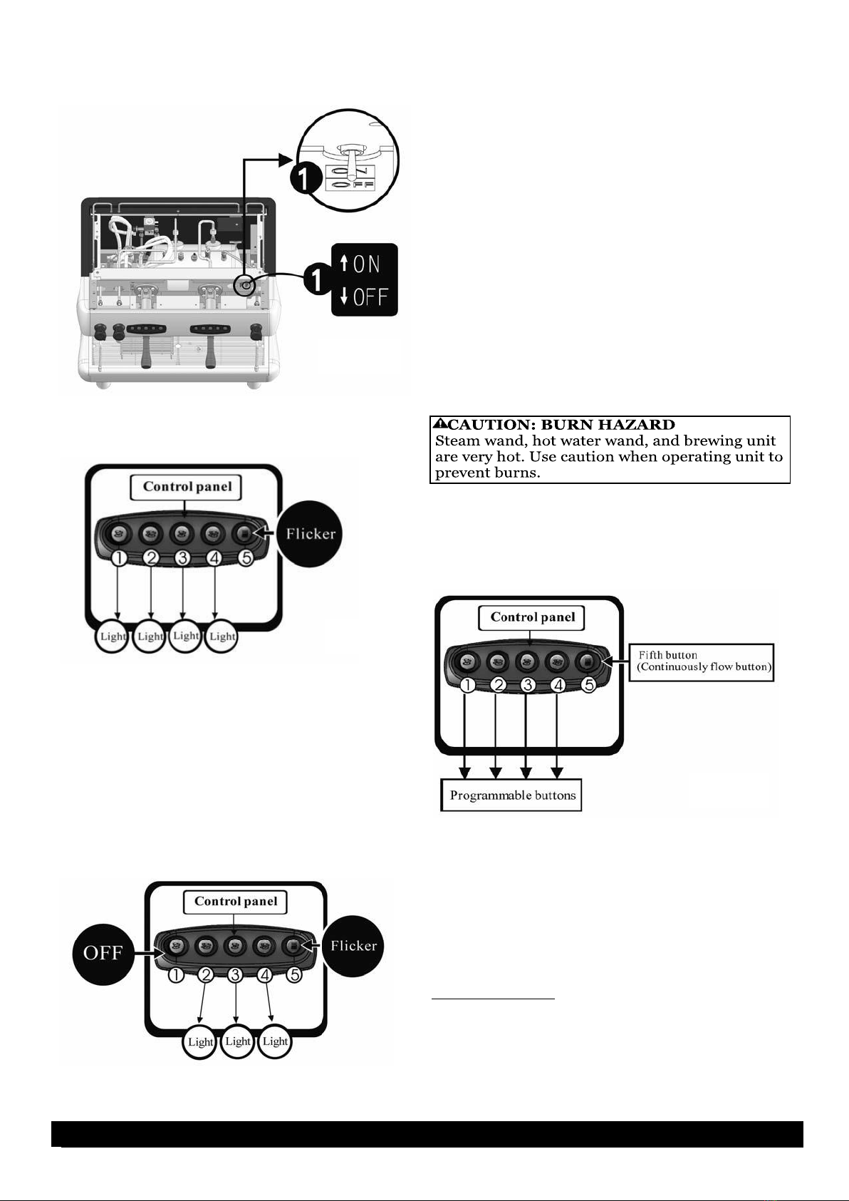
6.
Activate the Power Switch on front of unit (see
Figure H). The tank will fill in approximately
3-4 minutes.
Figure H
7.
Press continuous flow button on each control
panel (right button) to verify water flow.
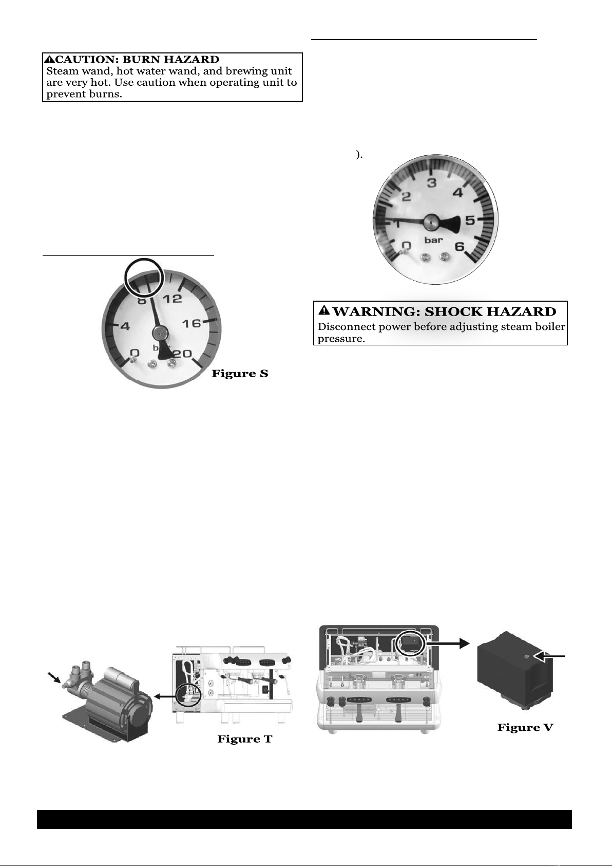
8.
After installing the machine, verify that during
water intake the steam boiler pressure gauge
indicator is within the green zone (1~1.4bar)
and the pump pressure gauge indicator, when
using the continuous flow button, is also
within the green zone (8~10bar). In case of
need to adjust the pressure, refer to
Adjustments section.
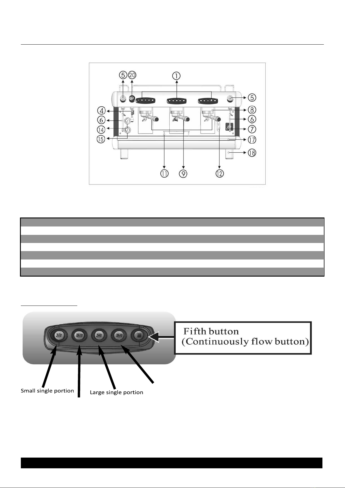
Programming
Control Panel
There are two identical control panels on two-cup
models and three identical control panels on 3-
cup models. No default coffee output setting is
provided. Settings must be made manually during
set-up. If you are using a multi-cup machine,
settings made on the farthest right hand side
control panel will serve as the default for the
others. Therefore, to set different values for
different cup compartments, begin set up from
the right and work your way to the left, to prevent
the previous setting from being overwritten.
WARNING: ELECTRIC SHOCK HAZARD!
Installation of this appliance should be
performed by qualified service personnel only.
Improper installation could result in
electrocution.
CAUTION: BURN HAZARD
Steam wand, hot water wand, and brewing unit
are very hot. Use caution when operating unit to
prevent burns.
Italia Espresso Machine Monaco Food Service ® ® 6
4 Grindmaster® CS EspressoMachine

Programming (continued)
1.
Turn on the programming switch.
(see
Figure I
)
2.
The LED of buttons 1 - 4 on the control panel
will be lit, and the fifth LED will flicker. This
indicates programming mode for setting up the
amount of continuous output. (See
Figure J
)
3.
Place measuring cup under the brewing group.
Hold down the first button until reaching the
required amount of water. Do not otherwise
touch the panel. Meanwhile the first button’s
light will be off, the other three buttons still lit,
and the fifth button flickers (see
Figure K
). It
means the first button is programmed. Continue
programming other buttons. Turn programming
switch to OFF when completed. Each time the
programming switch is turned ON, it will reset
the buttons.
Operation
NOTICE: To avoid overheating, electric wires should
be kept untangled and free of obstructions. Don’t block
air intake or outlet vents on the machine. Never cover
or otherwise prevent the free flow of air across the cup
warmer.
NOTICE: Do not use cleansers, bleach liquids,
powders
or any other substance containing chlorine. These
products promote corrosion and will pit the stainless
steel. USE OF THESE PRODUCTS WILL VOID THE
WARRANTY.
1.
Place an appropriate quantity of ground coffee in the
portafilter and tamp the ground coffee firmly. Clean all
residual coffee from the rim and sides of the filter. This
is to ensure a good seal and full pressure when brewing
coffee, and prolong the lifetime of the gasket. Attach the
portafilter to the machine by rotating until it locks in
place.
2.
Place cup(s) or glass(es) under spout(s).
3.
Either press desired portion button or press and hold
the continuous flow button until desired portion is
dispensed. To stop flow at any time, press and release
continuous flow button. (See Figure L)
4.
Mov
e cup(s) or glass(es) to side and remove
portafilter. Dump grinds. Carefully hold
portafilter near group head and rinse using the
continuous flow button water. Use extreme
caution to avoid burns. Then, fit empty Porta
Filter to the brewing group to store and keep
warm.
Steam Wand:
This can be used by turning the knob
counterclockwise, which allows for a varied
amount of steam or by pulling out the handle
which will dispense the maximum amount of
steam.
Figure I
Figure J
Italia Espresso Machine Monaco Food Service ® ® 7
4 Grindmaster® CS EspressoMachine
Figure L
KK
Figure K

Operation (continued)
Steam Wand (continued)
1.
To drain condensate, ensure steam wand is
pointed toward the drain grid and pull handle out
briefly to dispense a small amount of steam.
2.
Pour cold milk in a pitcher and place steam arm
into pitcher. Hold pitcher with one hand and turn
on steam, either by twisting to add a controlled
amount or pulling knob out to add steam at full
pressure.
3.
Remove pitcher.
4.
Wipe arm and nipple clean with soft cloth
moistened with sanitizer solution after each use.
After wiping, pull steam knob to release a steam
burst through the tube to remove any residual
milk remaining in the nozzle.
NOTICE:
Remove the pitcher from the steam
tube after foaming milk. Failure to do so may
draw liquid from the pitcher into the steam tube,
risking machine
component contamination.
Hot Water
1.
Turn the hot water knob counterclockwise to
obtain hot water through hot water wand. Hot
water output will increase the further the hot
water knob is turned. Turn the knob clockwise to
reduce/stop hot water output.
2.
You can also pull the knob straight out in order
to obtain hot water.
Cleaning
NOTICE:
All sanitizing agents in the food zone
must comply with 21 CFR 178.1010. Sanitize all
food dispensing units periodically. All parts to be
sanitized must be cleaned first. Cleaning and
sanitizing frequency must follow state and local
health department regulations.
NOTICE:
Wipe the accessories with a soft cloth
or specific detergent powder. Don’t use scrub
sponge or wire brushes.
After each brewing
1.
Carefully hold Porta Filter near group head and
rinse Porta Filter using the continuous flow
button water. Water is hot - use extreme caution.
2.
Wipe arm and nipple clean with soft cloth
moistened with sanitizer solution after each use.
3.
After wiping, pull steam knob to release a
steam burst through the tube to remove any
residual milk remaining in the nozzle.
Daily
Exterior:
Wipe the machine exterior with soft, slight
dampened cloth daily before starting operations.
If necessary, a mild, non-corrosive cleaning
agent may be applied to the cloth.
Back flushing:
1.
Remove screw (E), shower screen (D), and
plate (C) from the group head (be careful, metal
components may be hot). (
see Figure M
)
2.
Place the rubber disc in Porta Filter (
see
Figure N
), and apply about 2-3 grams of
espresso machine detergent/sanitizer on top of
rubber disc. Attach the portafilter to the group
head and check for tightness.
3.
Press first and fifth buttons simultaneously to
start automatic back flushing function. The first
and fifth button will be off, and middle three
buttons will be lit. This auto back flushing system
will complete 10 cleaning cycles. (
see Figure O
)
NOTE:
If you want to discontinue the cleaning, press
3rd button to stop.
Italia Espresso Machine Monaco Food Service ® ® 8
4 Grindmaster® CS EspressoMachine
Figure M
KK
Figure N
KK
Silica Gel Washer

Cleaning (continued)
4.
After automatic back flushing cycle is
complete, rinse Porta Filter and rubber disc with
water from the continuous flow button until
water in portafilter appears clean.
5.
Replace rubber disc on Porta Filter, then place
portafilter on the group head and press first and
fifth buttons simultaneously to start automatic
back flushing function to rinse. The first and fifth
button will be off, and middle three buttons will
be lit. This auto back flushing system will
complete 10 cleaning cycles.
NOTE: If you want to discontinue the cleaning,
press 3
rd
button to stop.
6.
Screw (E), shower screen (D), and plate (C)
should be cleaned and sanitized with the Porta
Filter, steam wand nipple and hot water wand
sprayer.
Cleaning and sanitizing portafilter:
Notice:
To avoid damage, do not immerse
espresso Porta Filter handle in water. Do not put
group gasket (item B from
Figure M
) in water or
any liquid detergent.
1. Disassemble Porta Filter. (see
Figure P
)
2.
Remove sprayer from hot water wand.
3.
Remove nipple from steam arm.
4.
Add loose group head parts [screw (E), shower
screen (D), and plate(C) from
Figure M
].
5. Use brush to clean and wash parts in detergent or
espresso urn cleaner/sanitiser. DO NOT immerse
Porta Filter handle. (see
Figure Q
)
6. Rinse parts.
7.
Prepare a sanitizing solution in accordance
with local health department regulations. You
may also refer to the US Food and Drug
Administration regulation 21 CFR 178.1010
“Sanitizing Solutions” and US Environmental
Protection Agency 40 CFR 18.940 “Tolerance
exemptions for active and inert ingredients for
use in antimicrobial formulations (Food-contact
surface sanitizing solutions)”.
8.
Follow the instructions provided with the
sanitizing agent.
9.
Let all sanitized parts drain and dry naturally.
DO NOT WIPE THEM DRY.
10. Reassemble parts.
Drain Tray and Discharge Trough:
1.
Remove and wash the drain tray after stopping use.
(see Figure R)
2.
Wipe and remove sediments in the discharge trough
with a wet cloth and wash with hot water to clear the
discharge tube.
3.
If water does not discharge properly, place a teaspoon
of detergent into the discharge trough and flush with hot
water to dissolve residual oils in the tube.
4.
Reassemble after the water tray has dried.
Figure O
KK
Figure Q
KK
(Do not immerse it in water)
Italia Espresso Machine Monaco Food Service ® ® 9
4 Grindmaster® CS EspressoMachine
Figure R
KK

Adjustments
NOTICE:
Please contact your authorized
service representative to undertake these
procedures.
The rest of this manual contains information to
aid the service technician who is maintaining this
equipment. This section has information on
performing common service tasks.
Pump Pressure Adjustment
The pump pressure has been factory adjusted to
9 bar (the recommended pressure). After
machine starts up and water refills, press
continuous flow button and read pressure on
pressure gauge if the indicator is on green zone
(8-10 bar) as shown in
Figure S
.
If the pressure is not in the green zone, adjust
pressure as shown below:
1.
Remove left side panel
2.
Attach Porta Filter into the brewing group
with filled ground coffee.
3.
Press continuous flow button. Turn screw
clockwise as shown in
Figure T
to increase
pressure; turn counterclockwise to reduce
pressure.
Steam Boiler Pressure Calibration
Steam boiler pressure is controlled by pressure
switch. The pressure inside the boiler continues to
rise as the water is heated by the heating
elements. Reducing pressure will reduce
temperature, while increasing pressure will
increase temperature. The steam boiler has been
factory adjusted to 1.2bar, (the recommended
pressure).
Please check if your pressure on the pressure
switch is 1.2bar or on the green zone (1-1.4bar)
(see Figure U). if so, you don’t need to adjust the
pressure. In case there is a need to calibrate the
pressure, please follow below procedure for
calibration:
NOTE: Please turn off the machine before
undertaking this operation.
1.
Turn off machine.
2.
Remove top cover of machine, and locate the
pressure switch on the upper right size.
3.
Remove the yellow case from the pressure
switch. Use screw to adjust the pressure as
shown in
Figure V
. Turn screw clockwise to
decrease pressure, or counterclockwise to
increase pressure. A complete screw turn
results in 0.1 bar variation.
Italia Espresso Machine Monaco Food Service ® ® 10
Figure U

Draining
If espresso machine will not be used for an
extended period, will be stored, or transported,
drain tank to prolong life and prevent damage from
freezing.
1.
Turn off the machine, and release all the
pressure from boiler by turning on the steam
knob(s).
2.
After the steam is completely released and the
pressure on steam boiler pressure gauge reads
“0”, remove drain tray and locate drain valve
under drain tray. Turn on drain valve to drain
water out of boiler. Drain valve is on when it is
parallel to pipe.
NOTE: Please DO NOT turn off the steam knob
after the steam is released for storage. Keep the
steam knob on. When you re-start the machine, do
not turn off the steam knob until you see water
drop from the steam wand. This is to balance the
boiler pressure.
3.
Turn off drain valve when water stops flowing
into waste cup. Drain valve is off when it is
perpendicular to pipe.
Troubleshooting
Before you call for help, please read the following:
INDICATION
PROBABLE CAUSE
SOLUTION
All lights on
control panel
turn on
After two minutes of water
input, indicator still does not
show a rise in machine water
level. It will take more than two
minutes to replenish water when
the machine is used for the first
time.
Water level probe not
functioning properly.
Water intake solenoid is
out of order.
Input water flow has been
interrupted.
Make sure that the water
valve is turned on and
there is water flowing into
machine.
Turn off machine.
Restart after 3 seconds.
Turn water supply on.
All lights on
ONE
control panel
flash
No water output from brewing
group.
Brewing for a long time
without reaching setup value.
Coffee grounds are too fine.
Water intake solenoid is
out of order.
Flow meter is out of order.
Adjust fineness of coffee
grinds.
Turn off machine. Restart
after 3 seconds.
Press any key to eliminate
the breakdown signal, and
notify qualified service
technician.
Note: Wait at least 3 seconds to restart the machine after turning it off to ensure previous error stored in memory
is cleared.
If you need help, call Monaco Food Services Technical Service Department, Phone call&time. Please have the model
and serial number ready so that accurate information can be given.
Prior authorization must be obtained from Monaco Food Services for all warranty claims.
Monaco Food Services provides the industry’s BEST warranty. Visit our website at ? for warranty terms and
conditions.
Italia Espresso Machine Monaco Food Service ® ® 11
WARNING:
To reduce the risk of electrical shock, unplug the dispenser power cord before
repairing or replacing any internal components of the unit. Before any attempt to replace a
component, be sure to check all electrical connections for proper contact. Only a qualified service
technician should perform electrical and mechanical adjustments or repairs.

Parts Diagram
Body Parts VENEZIA1-110, VENEZIA1-220
Item
Part #
Description
Item
Part #
Description
1
SCREW M4*16
18
SCREW M4*5 (SUS)
2
LEFT SIDE PANEL(BLACK)
19
FOOT
3
SCREW M4*5
20
NUT M10
4
CABLE COVER
21
BOTTOM METAL COVER (ETL)
5
TOP RIGHT SIDE PANEL
SUPPORT
22
CABLE PROTECTION RING (ETL)
6
SURROUND STEEL
23
SCREW ( 4mm*15 )
7
TOP LEFT SIDE PANEL
24
DOWN RIGHT SIDE PANEL
8
BASE FRONT PANEL
25
S.STEEL BOILER COVER
9
OPERATE FACEPLATE
26
RIGHT SIDE PANEL (BLACK)
10
DOWN LEFT SIDE PANEL
27
BACK PANEL(BLACK)
11
VALVE COVER
28
TOP RIGHT SIDE PANEL
12
CUP RACK
29
TOP LEFT SIDE PANEL SUPPORT
13
BASE FRONT PANEL
30
UPPER STAINLESS STEEL GRILL
14
DRAIN PAN
31
CUP FENCE-RIGHT
15
LOWER DRAIN PAN
32
CUP FENCE -REAR
16
DRAIN TUBE 5/8" HIGH TEMP
33
GROUP COVER
17
SCREW M6*8
34
CUP FENCE-LEFT
Italia Espresso Machine Monaco Food Service ® ® 12
1
2
3
4
5
6
7
8
9
10
11
12
13
14
15
16
17
18
19
20
21
22
23
24
25
26
27
3
28
29
30
31
32
33
34

Parts Diagram
Body Parts VENEZIA2-220
Item
Part #
Description
Item
Part #
Description
1
SCREW M4*16
19
DRAIN TUBE 5/8" HIGH TEMP
2
SCREW M4*5
20
SCREW M6*8
3
LEFT SIDE PANEL(BLACK)
21
SCREW M4*6
4
GROUP COVER
22
BOTTOM METAL COVER (ETL)
5
SCREW M4*8 (SUS)
23
FOOT
6
TOP RIGHT SIDE PANEL SUPPORT
24
NUT M10
7
CABLE COVER
25
CABLE PROTECTION RING (ETL)
8
TOP LEFT SIDE PANEL
26
S.STEEL BOILER COVER
9
OPERATION PANEL
27
DOWN RIGHT SIDE PANEL
10
SURROUND STEEL
28
TOP RIGHT SIDE PANEL
11
VALVE COVER
29
TOP LEFT SIDE PANEL SUPPORT
12
OPERATE FACEPLATE
30
RIGHT SIDE PANEL (BLACK)
13
DOWN LEFT SIDE PANEL
31
BACK PANEL(BLACK)
14
CUP RACK
32
CUP FENCE-RIGHT
15
LOWER DRAIN PAN
33
UPPER STAINLESS STEEL GRILL
16
DRAIN PAN
34
CUP FENCE-REAR
17
BASE SURROUND FRONT
35
CUP FENCE-LEFT
18
SCREW ( 4mm*15 )
Italia Espresso Machine Monaco Food Service ® ® 13
1
2
3
4
5
6
7
8
9
10
11
12
13
14
15
16
17
21
20
19
18
22
23
24
25
26
27
5
28
29
30
31
32
33
34
35

Parts Diagram
Body Parts VENEZIA3-220
Item
Part #
Description
Item
Part #
Description
1
CUP FENCE-LEFT
19
BOTTOM METAL COVER (ETL)
2
SCREW M4*16
20
FOOT
3
LEFT SIDE PANEL(BLACK)
21
NUT M10
4
SCREW M4*8 (SUS)
22
SCREW M4*6
5
TOP RIGHT SIDE PANEL SUPPORT
23
CABLE PROTECTION RING (ETL)
6
CABLE COVER
24
SCREW ( 4mm*15 )
7
TOP LEFT SIDE PANEL
25
DOWN RIGHT SIDE PANEL
8
OPERATION PANEL
26
SCREW M6*8
9
OPERATE FACEPLATE
27
SCREW M4*5
10
DOWN LEFT SIDE PANEL
29
TOP RIGHT SIDE PANEL
11
S.STEEL BOILER COVER
30
TOP LEFT SIDE PANEL SUPPORT
12
CUP RACK
30
RIGHT SIDE PANEL (BLACK)
13
LOWER DRAIN PAN
31
BACK PANEL(BLACK)
14
DRAIN PAN
32
CUP FENCE-RIGHT
15
BASE SURROUND FRONT
33
GROUP COVER
16
VALVE COVER
34
CUP FENCE-REAR
17
SURROUND STEEL
35
UPPER STAINLESS STEEL GRILL
18
DRAIN TUBE 5/8" HIGH TEMP
Italia Espresso Machine Monaco Food Service ® ® 14
1
2
3
4
5
6
7
8
9
10
11
12
13
14
17
16
15
18
19
27
4
26
20
22
21
23
24
25
28
29
27
30
31
4
32
33
34
35

Parts Diagram
Motor Part Assembly
Item
Part #
Description
1
S.T. STEEL WIRE PIPE (600mm)
2
MOTOR 220-240V 50/60Hz 1.6A (UL)
3
CAPACITOR 10μF
4
PUMP FOR VENEZIA1-220
4
PUMP FOR VENEZIA2 & VENEZIA3
4
PUMP FOR VENEZIA1-110
5
PIPE GASKET TEFLON
6
NPT FITTING NPT3/8"*NPT1/2"
7
S.T. STEEL WIRE PIPE (2400mm)
Italia Espresso Machine Monaco Food Service ® ® 15
1
2
7
3
6
5
4
7

Parts Diagram
Boiler Hydraulic Circuit Venezia1
Item
Part #
Description
Item
Part #
Description
1
LEVEL PROBE ASSEMBLY
27
WATER LEVEL LOWER TUBE
2
ANTI-EDDY VALVE V.A.R.
28
SI-GASKET ELEMENT
3
VALVE GASKET BRASS
29
HEATING ELEMENT 2000W CE
4
SAFETY VALVE
29
HEATING ELEMENT 1500W 110V)
5
HEAT EXCHANGER OUTLET TUBE
30
HEX SCREW (M10*16)
6
WATER LEVEL UPPER TUBE
31
ELBOW BRASS 5/16*1/4
7
HEAT EXCHANGER RETURN TUBE
32
BRASS PLUG
8
STEAM PRESSURE GAUGE TUBE
33
AUT.WATER REFILL TUBE REAR
9
BRASS CONNECTOR 1/2-20UNF*PT1/4
34
PRESSURE GAUGE COPPER TUBE
10
HOT WATER OUTLET TUBE REAR
35
STEAM OUTLET TUBE FRONT RIGHT
11
BOILER
36
VALVE GASKET BRASS
12
AUT.WATER REFILL TUBE
37
BRASS CONNECTOR 1/4"X1/8"
13
HEAT EXCHANGER INLET TUBE
38
SOL. VALVE WATER REFILL ASSY 208~240V
60Hz
14
BRASS FITTING PS/1/4*PS1/4*L33.5
39
BRASS CONNECTOR PT1/4*1/2-20UNF*1/2-
20UNF
15
BRASS FITTING PS/1/4*PS1/4*L42
40
BRASS CONNECTOR
16
FLOWMETER DOSER
41
SPHERICAL BRONZE CONICAL FILTER
17
FLOW METER GAUGE
42
NBR O RING
18
ELBOW BRASS PT3/8*3/8
43
LEVEL PROBE BASE
19
FLOWMETER INLET TUBE
44
PROBE FIXED SUPPORT
20
S.C.N.R.DOSER VALVE 1/2*1/2*1/2
45
PROBE FIXED BOLT
21
BOILER DRAIN TUBE FRONT
46
PROBE ( SUS304 /3mm L132 )
22
EXPANSION DRAIN TUBE
47
BRASS NUT
23
NUT M8
48
TEFLON WASHER
24
SPRING WASHER M8
49
SI O-RING
25
PRESSURE RELEASE TAP BULK
PS1/4xPS1/4
50
SHAFT
26
BOILER DRAINTUBE REAR
51
ANTI-EDDY VALVE BASE
Italia Espresso Machine Monaco Food Service ® ® 16
1
2
3
4
5
6
7
8
9
10
3
11
3
12
13
15
14
22
16
17
20
19
21
18
23
24
25
26
27
28
29
30
31
32
33
34
35
36
37
39
38
41
42
40
43
44
45
46
1
47
48
49
50
51
2

Parts Diagram
Boiler Hydraulic Circuit Venezia2
Item
Part #
Description
Item
Part #
Description
1
VALVE GASKET BRASS
27
SPRING WASHER M8
2
ANTI-EDDY VALVE V.A.R.
28
WATER LEVEL LOWER TUBE
3
VALVE GASKET BRASS
29
SI-GASKET ELEMENT
4
HEAT EXCHANGER OUTLET TUBE LEFT
30
HEATING ELEMENT 4000W (CE)
5
HOT WATER CONDUCT TUBE IN BOILER
31
HEX SCREW (M10*16)
6
STEAM OUTLET TUBE FRONT RIGHT
32
AUT.WATER REFILL TUBE REAR
7
HOT WATER OUTLET TUBE REAR
33
WATER LEVEL UPPER TUBE
8
STEAM OUTLET TUBE FRONT LEFT
34
PRESSURE GAUGE COPPER TUBE
9
BOILER
35
BRASS CONNCTR PT1/4*1/2-20UNF*1/2-
10
AUT.WATER REFILL TUBE
36
BRASS CONNECTOR 1/4"X1/8"
11
HEAT EXCHANGER RETURN TUBE LEFT
37
SOL. VALVE WATER REFILL ASSY
208~240V 60Hz
12
HEAT EXCHANGER RETURN TUBE
RIGHT
38
BRASS CONNECTOR
13
ELBOW BRASS PT3/8*3/8
39
SPHERICAL BRONZE CONICAL FILTER
14
BRASS FITTING PS/1/4*PS1/4*L33.5
40
NBR O RING
15
BRASS FITTING PS/1/4*PS1/4*L42
41
HEAT EXCHANGER OUTLET TUBE
RIGHT
16
FLOWMETER DOSER
42
SAFETY VALVE
17
FLOW METER GAUGE
43
LEVEL PROBE ASSEMBLY
18
EXPANSION DRAIN TUBE
44
BRASS NUT
19
S.C.N.R.DOSER VALVE 1/2*1/2*1/2
45
TEFLON WASHER
20
FLOWMETER INLET TUBE
46
SI O-RING
21
HEAT EXCHANGER INLET TUBE
47
SHAFT
22
BOILER DRAIN TUBE FRONT
48
ANTI-EDDY VALVE BASE
23
PRESSURE RELEASE TAP BULK UNIT
PS1/4xPS1/4
49
PROBE ( SUS304 /3mm L132 )
24
BOILER DRAINTUBE REAR
50
PROBE FIXED BOLT
25
ELBOW BRASS 5/16*1/4
51
PROBE FIXED SUPPORT
26
NUT M8
52
LEVEL PROBE BASE
Italia Espresso Machine Monaco Food Service ® ® 17
1
2
3
4
5
6
7
8
9
10
3
11
12
13
14
22
16
17
20
19
21
18
23
24
25
27
26
28
29
30
31
32
33
34
35
36
37
39
38
41
3
40
43
42
44
45
46
47
48
2
15
50
49
43
51
52

Parts Diagram
Boiler Hydraulic Circuit Venezia3
Item
Part #
Description
Item
Part #
Description
1
NBR O RING
29
WATER LEVEL LOWER TUBE
2
BRASS CONNCTR PT1/4*1/2-20UNF*1/2-
30
HEX SCREW (M10*16)
3
HOT WATER OUTLET TUBE REAR
31
HEATING ELEMENT 6000W (CE)
4
STEAM OUTLET TUBE FRONT LEFT
32
SI-GASKET ELEMENT
5
VALVE GASKET BRASS
33
AUT.WATER REFILL TUBE REAR
6
STEAM OUTLET TUBE FRONT RIGHT
34
WATER LEVEL UPPER TUBE
7
STEAM PRESSURE GAUGE TUBE
35
BOILER
8
HEAT EXCHANGER RETURN TUBE MIDDLE
36
HEAT EXCHANGER OUTLET TUBE RIGHT
9
HEAT EXCHANGER RETURN TUBE RIGHT
37
STEAM OUTLET TUBE FRONT RIGHT
10
AUT.WATER REFILL TUBE
38
HEAT EXCHANGER OUTLET TUBE MIDDLE
11
BRASS FITTING PS/1/4*PS1/4*L33.5
39
ANTI-EDDY VALVE V.A.R.
12
BRASS FITTING PS/1/4*PS1/4*L42
40
HEAT EXCHANGER OUTLET TUBE LEFT
13
FLOWMETER DOSER
41
VALVE GASKET BRASS
14
FLOW METER GAUGE
42
LEVEL PROBE ASSEMBLY
15
ELBOW BRASS PT3/8*3/8
43
SAFETY VAVLE
16
HEAT EXCHANGER INLET TUBE
44
BRASS CONNECTOR 1/4”X1/8”
17
EXPANSION DRAIN TUBE
45
SOL. VALVE WATER REFILL ASSY
208~240V 60Hz
18
S.C.N.R.DOSER VALVE 1/2*1/2*1/2
46
BRASS CONNECTOR
19
BOILER DRAIN TUBE FRONT
47
SPHERICAL BRONZE CONICAL FILTER
20
PRESSURE RELEASE TAP BULK UNIT PS1/4xPS1/4
48
PROBE ( SUS304 /3mm L132 )
21
HEAT EXCHANGER INLET TUBE MIDDLE
49
PROBE FIXED BOLT
22
FLOWMETER INLET TUBE
50
PROBE FIXED SUPPORT
23
HEAT EXCHANGER RETURN TUBE LEFT
51
LEVEL PROBE BASE
24
HEAT EXCHANGER INLET TUBE RIGHT
52
BRASS NUT
25
BOILER DRAIN TUBE REAR
53
TEFLON WASHER
26
NUT M8
54
SI O-RING
27
SPRING WASHER M8
55
SHAFT
28
ELBOW BRASS 5/16*1/4
56
ANTI-EDDY VALVE BASE
Italia Espresso Machine Monaco Food Service ® ® 18
1
2
3
4
5
7
6
8
9
10
12
11
13
14
15
16
17
18
19
20 21
22
23
24
25
26
28
27
29
30
31
32
33
34
35
36
28
37
38
39
41
44
43 42
45
47
46
52
53
54
55
56
39
51
50
49
48
42

Parts Diagram
Water Level Assembly
Item
Part #
Description
1
HEX SCREW (M8*10)
2
SIGHT GLASS RUBBER GASKET 10.69*ψ 3.5
3
COPPER SEAL
4
BRASS NUT
5
LEVEL-INDICATING BALL
6
SIGHT GLASS
7
PC PANNEL
8
WASHER (M8*3t)
9
LAVEL CONNECTOR (LOWER)
11
WATER LEVEL ASSEMBLY
12
SIGHT GLASS REAR COVER
13
LEVEL CONNECTOR (UPPER)
Italia Espresso Machine Monaco Food Service ® ® 19
1
2
3
4
5
6
7
2
1
8
9
3
4
10
11
12
13
8

Parts Diagram
Distribution Group Assembly
Item
Part #
Description
Item
Part #
Description
1
DISTRIBUTION GROUP CAP
13
PRESSURE RELEASE DRAIN TUBE
2
TEFLON GASKET D22*d18*2.0
14
HEX SCREW M4*12
3
GROUP FILTER ST.STEEL
D13.8*d10.5*11.5
15-1
ODE GROUP SOLENOID VALVE COIL 110V
4
HEX NOZZLE
15-2
ODE GROUP SOLENOID VALVE COIL
208~240V
5
STAINLESS STEEL SCREW M5*10
16
DISTRIBUTION GROUP ASSEMBLY
6
DISTRIBUTION GROUP BODY
17
BRASS PLUG
7
SI_O-RING d47*3.5t
18
WATER INLET CONNECTOR
8
CHROMED CLAMPING RING
19
GROUP WASHER
9
FILTER GROUP GASKET
20
PT1/4x5/8-18UNF L_FITTING
10
GROUP PLATE
21
WATER RECYCLE CONNECTOR
11
GROUP SHOWER SCREEN
22
DISTRIBUTION GROUP ASSEMBLY
12
STAINLESS STEEL FLATHEAD SCREW
M5*15
Italia Espresso Machine Monaco Food Service ® ® 20
Venezia 1-110V/220V Venezia 2, Venezia 3
15-1
15-2
This manual suits for next models
3
Table of contents