Monacor VNC-3052 User manual

1/74
User Manual
BULLET
IP CAMERA

2/74
WARNING
TO REDUCE THE RISK OF FIRE OR ELECTRIC SHOCK, DO NOT EXPOSE THIS
PRODUCT TO RAIN OR MISTURE.
DO NOT INSERT ANY METALLIC OBJECT THROUGH VENTILATION GRILLS.
CAUTION
CAUTION
RISK OF ELECTRIC SHOCK
DO NOT OPEN
CAUTION:TO REDUCE THE RISK OF ELECTRIC SHOCK.
DO NOT REMOVE COVER (OR BACK).
NO USER-SERVICEABLE PARTS INSIDE.
REFER SERVICING TO QUALIFIED SERVICE PERSONNEL.
COPYRIGHT
THE TRADEMARKS MENTIONED IN THE MANUAL ARE LEGALLY REGISTERED
TO THEIR RESPECTIVE COMPANIES.

3/74
Content
I. PREFACE ............................................................................................................4
II. PRODUCT SPECIFICATIONS.............................................................................4
III. PRODUCT INSTALLATION.................................................................................8
A. MONITOR SETTING......................................................................................................8
B. HARDWARE INSTALLATION ..........................................................................................9
C. IPASSIGNMENT.........................................................................................................14
D. INSTALLACTIVEXCONTROL:.....................................................................................18
IV. LIVE VIDEO.......................................................................................................24
V. IP CAMERA CONFIGURATION ........................................................................28
A. SYSTEM ....................................................................................................................29
B. NETWORK................................................................................................................. 34
C. A/VSETTING ............................................................................................................46
D. EVENT LIST...............................................................................................................53
VI. NETWORK CONFIGURATION..........................................................................63
VII. I/O CONFIGURATION .......................................................................................65
VIII. FACTORY DEFAULT.........................................................................................69
IX.UNIVERSAL PASSWORD.................................................................................70
X. PACKAGE CONTENTS.....................................................................................73
XI. MICRO SD CARD COMPATIBILITY..................................................................74

4/74
I. Preface
This is a 1 / 3” Megapixel CMOS Sensor Outdoor IP camera with a built-in web
server. The user can view real-time video via IE browser. It supports H.264,
M-JPEG, and MPEG4 video compression, providing smooth and high video quality.
The video can be stored in Micro SD card and playback remotely.
With a user friendly interface, it is an easy-to-use IP camera for security
applications.
II.Product Specifications
4 Megapixel IR Bullet Real Time IP Camera
External Vari-focal Lens Adjustment
Digital Noise Reduction
Power over Ethernet
Digital Wide Dynamic Range
Day & Night Manual Switch Time Control
IR LED Built-in 30M
IR Cut Filter Mechanism
H.264/ M-JPEG Compression
Micro SD Card Backup (Optional)
2-way Audio
IP66
Cable Management
Support iPhone/Android/Mac
SDK for Software Integration
Free Bundle 36 Ch Recording Software

5/74
Specifications
Hardware
CPU
Multimedia SoC
RAM
512MB
Flash
32MB
Image Sensor
1 / 3” Megapixel CMOS Sensor
Sensitivity
Color: 0.08 Lux (AGC ON)
B/W: 0.03 Lux (AGC ON)
Lens Type
Vari-focal Lens 2.8-12 mm @ F1.4
View Angle
34.47~92.42°(H), 19.42~48.24°(V)
ICR
IR cut Filter Mechanism
I/O
1 DI/ 1 DO
Power over Ethernet
Yes
Video Output
N/A
Audio
G.711(64K) and G.726(32K,24K) audio compression
Input : 3.5mm phone jack
Output: 3.5mm phone jack, Support 2-way.
Power Consumption
DC 12V Max: 6.36W(IR ON); 3.24W(IR OFF)
PoE Max: 8.16W(IR ON); 4.32W(IR OFF)
Operating Temperature
-20°C ~ 60°C
Dimensions
77.4 mm () x 172 mm (H)
Weight
920g
IR LEDs
LEDs
28 Units 5φ + 2 Units High Power, 850nM
IR Distance
30M

6/74
Network
Ethernet
10/ 100 Base-T
Network Protocol
IPv6, IPv4, HTTP, HTTPS, SNMP, QoS/DSCP,Access list, IEEE
802.1X, RTSP, TCP/ IP, UDP, SMTP, FTP, PPPoE, DHCP, DDNS, NTP,
UPnP, 3GPP, SAMBA, Bonjour
Wireless (Optional)
Wireless
802.11b/g/n
Security
WEP,WPA-PSK,WPA2-PSK
System
Video Resolution[16:9]
2688x1520@30fps, 1920x1080@30fps, 1280x720@30fps,
640x360@30fps
Video Adjust
Brightness, Contrast, Hue, Saturation, Sharpness,AGC, Night
Mode, WDR, Flip, Mirror, Noise Reduction, Day&Night
Adjustable
Triple Streaming
Yes
Image Snapshot
Yes
Full Screen Monitoring
Yes
Privacy Mask
Yes, 3 different areas
Compression Format
H.264/ M-JPEG
Video Bitrates Adjust
CBR, VBR
Motion Detection
Yes, 3 different areas
Triggered Action
Mail, FTP, Save to SD card, DO, SAMBA
Security
Password protection, IP address filtering, HTTPS encrypted data
transmission, 802.1X port-based authentication for network
protection, QoS/DSCP

7/74
Firmware Upgrade
HTTP mode, can be upgraded remotely
Simultaneous
Connection
Up to 10
Micro SD Card Management (Optional)
Recording Trigger
Motion Detection, IP check, Network break down (wire
only),Schedule, DI
Video Format
AVI, JPEG
Video Playback
Yes
Delete Files
Yes
Web Browsing Requirement
OS
Windows 7, 2000, XP, 2003, Microsoft IE 6.0 or above,
Chrome, Safari, Firefox
Mobile Support
iOS 4.3 or above, Android 1.6 or above
Hardware Suggested
Intel Dual Core 2.53G,RAM: 1024MB, Graphic card: 128MB
*SPECIFICATIONS ARE SUBJECT TO CHANGE WITHOUT NOTIFICATION.

8/74
III. Product Installation
A. Monitor Setting
i. Right-Click on the desktop. Select “ Properties”
ii. Change color quality to highest (32bit).

9/74
B. Hardware Installation
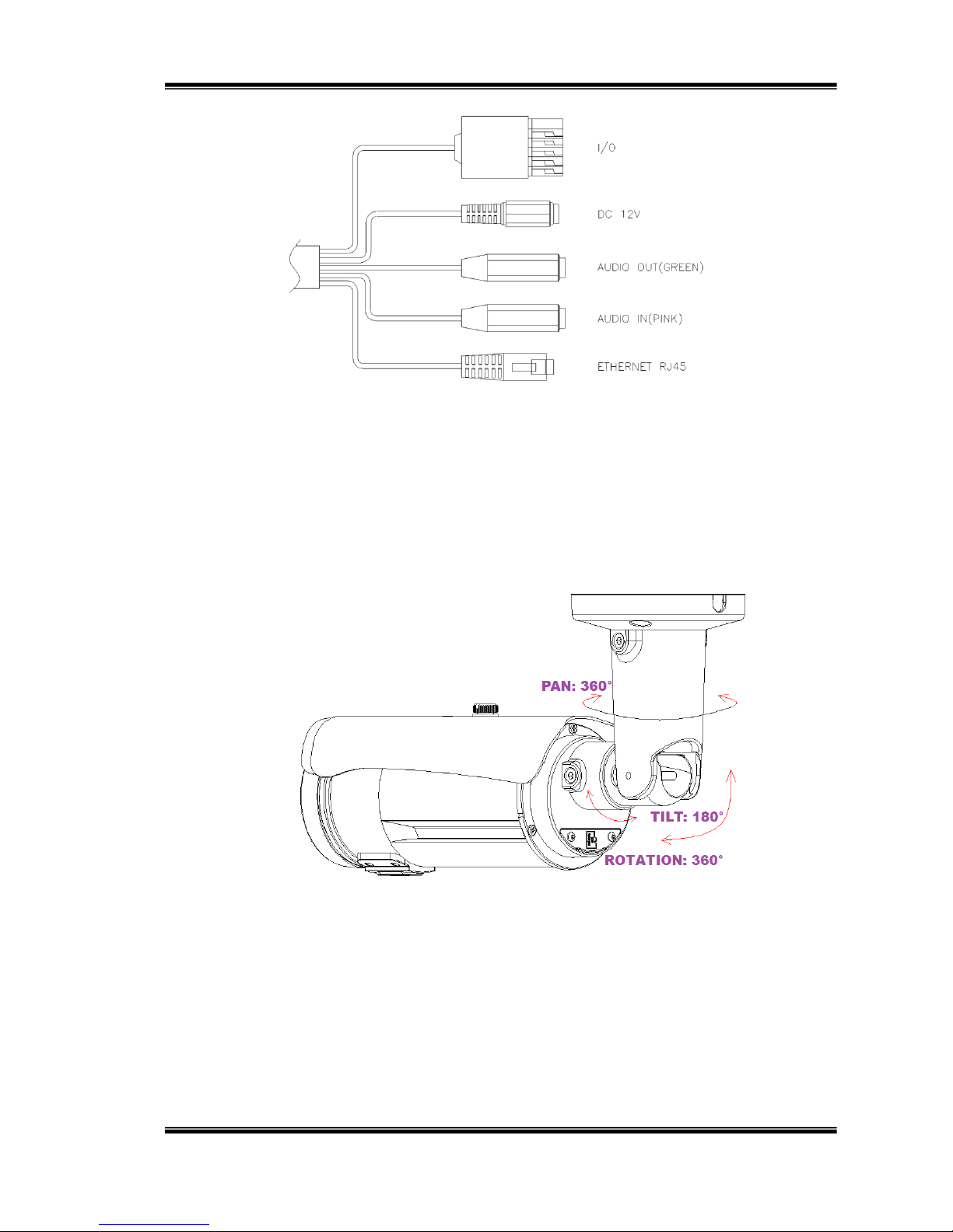
1. Connector Instruction
The Cable and connectors are as below. Connect power adaptor first, then
connect the IP Camera to PC or network, and set up the network configurations
according to the network environment. For I/O setting, please refer to User Manual:
"I/O Configuration" chapter for more descriptions.
10/74
2. 3-Axis Bracket
Use the 3-Axis bracket to adjust the camera to appropriate angle, then turn and
tighten the screw to fix it.
3. External Vari-focal lens controller
This IP camera is equipped with an external vari-focal lens controller.
Please adjust the “ZOOM” and “FOCUS” as the following picture until the image gets
Table of contents
Other Monacor IP Camera manuals


