SERVICE
REFRIGERATION - MEDIUM TEMP
“REFRIGERATION DIFFERENTIAL” MODE
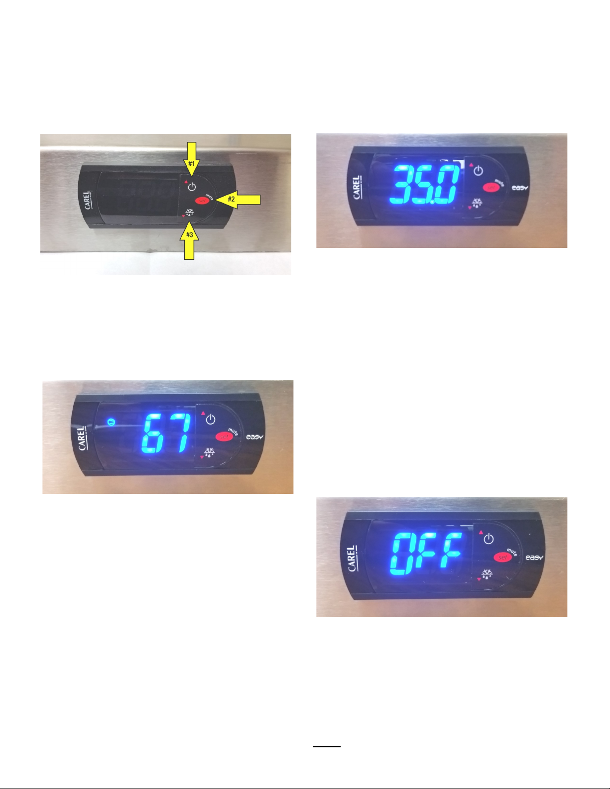
1. Hold down the “set” button (#2) for at least
five seconds until flashing “ PS” is shown.
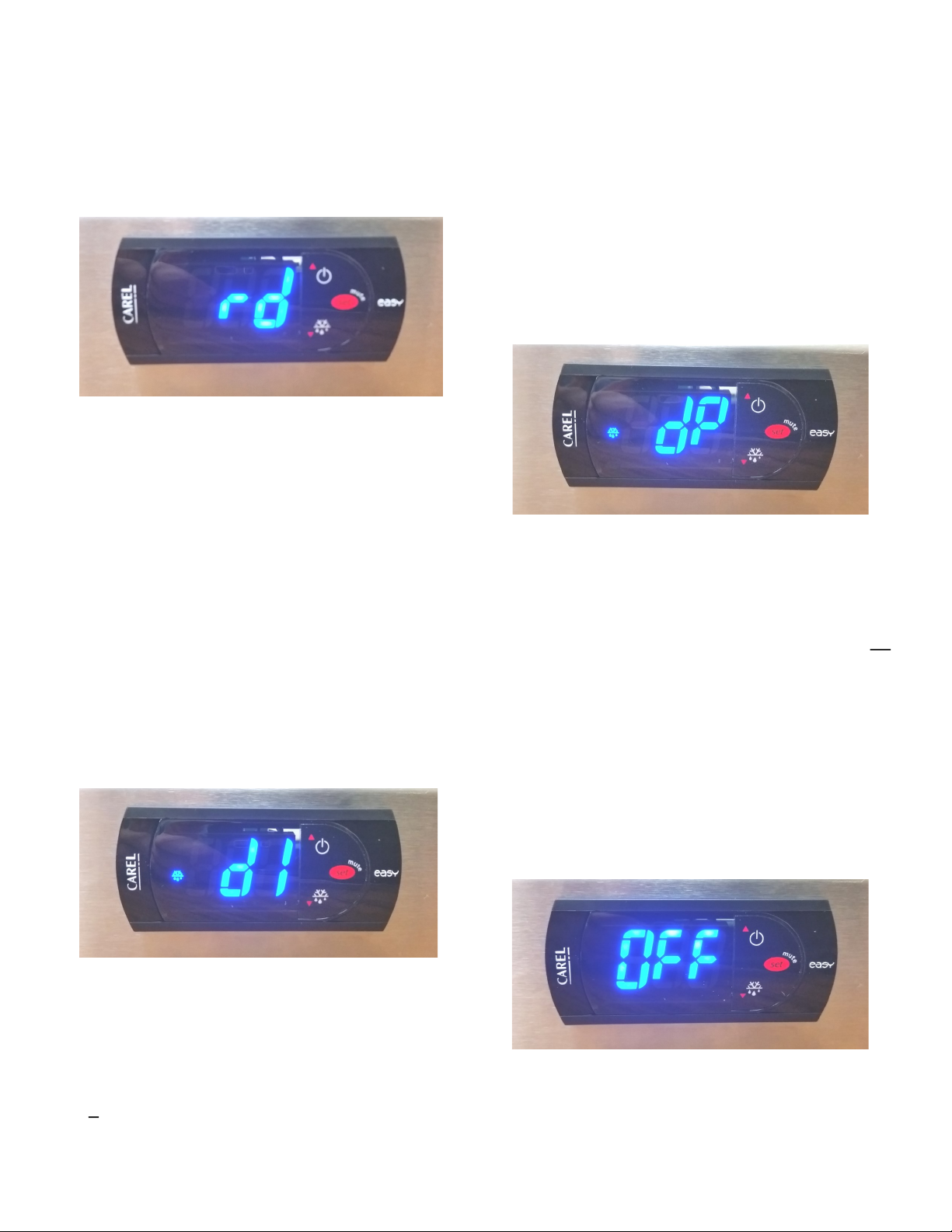
Press the “ up arrow” button (#1) to reach the
flashing “rd” and press the “set” button (#2)
once. Make sure that this is set to “5.0”, this
your refrigeration differential.
2. If an adjustment needs to be made to the set
temperature, use the “up arrow” button (#1)
or the “down arrow” button (#3) to adjust the
temperature. Press the “set” button (#2) to
save your adjustment. Doing this will send
you back to the menu showing a flashing
“rd”.
“DEFROST INTERVAL” MODE
1. Press the “up arrow” button (#1) to display
the “dI” parameter as shown and press the
“set” button (#2) once. Make sure that
this is set to “2” , this is equivalent to how
often the unit will begin defrost mode (every
2 hours).
2. If an adjustment needs to be made use the
“up arrow” button (#1) or the “down arrow”
button (#3) to adjust the hour. Press the “set”
button (#2) to save your adjustment. Doing this
will send you back to the hidden menu showing
a flashing “dI”.
“DEFROST PERIOD” MODE
1. Press the “up arrow” button (#1) to display
the “dp” parameter as shown and press the
“set” button (#2) once. Make sure that
this is set to “10”, this is equivalent to how
long the unit will be in defrost mode (10
minutes).
2. If an adjustment needs to be made use the
“up arrow” button (#1) or the “down
arrow” button (#3) to adjust the hour.
Press and hold the “set” button (#2) to save
your adjustment. Doing this will send you
back to operational mode.
“OFF” MODE
1. If for any reason your digital thermostat is
displaying a flashing “Temperature/Off” your
digital thermostat is in “Off” mode. To return
to the “On” mode, press and hold the
5