Montana Blitzer User manual

Blitzer Assembly Manual
Copyright © 2004 by Montana Design. All rights reserved.
Speed 400/480 Me-109
Specifications
Wingspan: 32½”
Wing Area: 177 sq in
Wing Loading: 12-16 oz/sq ft
Weight: 15-20 oz
Motor: Speed 400/480
or Brushless
Cells: 8-10 cells
Radio: 3 channels

Blitzer Assembly Manual
Copyright © 2004 by Montana Design. All rights reserved.
TABLE OF CONTENTS
INTRODUCTION: 2
KIT CONTENTS: 3
FUSELAGE ASSEMBLY: 4
WING ASSEMBLY: 9
HATCH ASSEMBLY: 16
EMPENNAGE ASSEMBLY: 17
FINISHING: 18
CONTROLS: 19
FLYING: 20

Blitzer Assembly Manual
Page 2of 21
INTRODUCTION:
The Blitzer is intended to be a next step up from our greatly-loved Blitzer Reno-style P-51. We increased
wing area, lowered the wing loading, and added room in the fuselage to make equipment installation easier.
The Blitzer is just as nice a flyer.
In the construction manual, we make only a few assumptions – the biggest is that you have built a model
airplane before. The Blitzer probably isn’t the best choice for a first construction, but it is certainly fine for a
second one. It is not good for inexperienced pilots, either, though the low wing loading will give an
experienced pilot the ability to fly just about any maneuver. As a pilot, you need to be able to handle a high-
speed aileron trainer as a minimum. Since we cannot control your building nor piloting skills, we can assume
no responsibility for your actions and any damage they may cause.
Please feel free to e-mail us your comments, positive or negative.
Andy
Montana Design
409 S. Sixth Street
Morris Park
Phillipsburg, NJ 08865
www.flyinghobbies.com

Blitzer Assembly Manual
Page 3of 21
KIT CONTENTS:
1/16” balsa sheets numbered Sheet 1 through Sheet 11
1/16” birch ply sheet Sheet 12
Balsa nose blocks (3 total)
(3) 1/8” square balsa, 24”
(4) 1/16” x 1/8” balsa, 24”
(2) ½” x 1” x 5” balsa wing tip blocks
Instruction Manual
Wing tip template
Rolled set of fuselage plans
CD-ROM – Includes electronic version of manual and many extra photographs.
HARDWARE BAG CONTENTS:
(2) Aileron push rod, pre-bent
(2) Hatch hold-down magnets
DuBro # 845 Micro E-Z Connectors for ailerons
Elevator control horn
Elevator Standard E-Z Connector for elevator
1/16” elevator pushrod
Fiberglass tape for wing root
ADDITIONAL REQUIRED ITEMS:
To help maintain the low cost of this kit and to give the builder maximum flexibility with preferred items, you
will need to purchase the following for use in the model:
Speed 480-class or brushless motor
Graupner 1311.16.8 39mm spinner & folding prop (1½” spinner)
Thin and medium CA and accelerator
5-minute epoxy
(3) HS-55 or equivalent servos
Plastic covering material (Ultra-Cote or equivalent) or paint finish
8-cell battery pack. KAN950 and HECELL 1100 cells were used in the prototypes
TOOLS:
Hobby knife with #11 blade
Fine point felt-tip pen or pencil
12” ruler/straight-edge
Motor tool with disk or sanding drum
Variety of sandpapers
Long sanding block (preferably one for each grade of paper)
Small building square
Packing tape
The CD-ROM included with this kit includes all the photographs in the printed manual, but in a much
larger size. In addition, a sizeable collection of all the photographs we took building the prototype may also
be found. The manual photos were cut from there.

Blitzer Assembly Manual
Page 4of 21
Photo 1
Photo 2
Photo 5
Photo 3 Photo 4
FUSELAGE ASSEMBLY:
1) Begin assembly of the fuselage by removing
the left and right fuselage sides and doublers
from their respective balsa sheets. Take care
with your knife to carefully extend the laser-cut
edges through the small retaining tabs. Test fit
the parts to see the orientation. All parts are
labeled with purpose, and most show alignment
marks to help guarantee proper assembly.
Photo 1 shows these four parts.
2) Spread a light coat of medium CA on one
fuselage doubler except for the front solid
section. This unglued area will allow the wood
to bend properly when it is wrapped around the
firewall in a later step.
Be sure to spread the glue on the side which will
face the fuselage, so as to make left and right
sides. Quickly press it down on the fuselage side, taking care to make sure they are properly aligned.
While holding the two sheets together, spray a light coat of accelerator on the doubler. The fumes will
penetrate the light wood and cause the CA to cure more quickly. See Photo 2.
3) On the fuselage sides are markings
showing where 1/8” square balsa is
used. Refer to the enclosed plans
and Photo 3. Each side will take
two pieces of wood cut to the
appropriate length along the bottom
edge, two more behind the cockpit,
and two small vertical pieces at the
leading edge of the wing. Be sure
to end each piece where it will
touch the formers.
Repeat these steps for the other side. Lightly sand the
edges where any glue make have squeezed out. When
we are attaching the bottom this will be sanded more
completely.
4) If you will be building your model for rudder control
(optional), refer to the cut-out lines drawn on the rear
fuselage side. These correspond to the elevator exit
hole on the left of the fuselage. NOTE: The included
servo elevator tray does NOT include a hole for the
rudder servo.
5) Using the same technique, laminate the formers shown
in Photo 5. Lightly sand the outer edges of the formers
to square them and remove excess glue.

Blitzer Assembly Manual
Page 5of 21
Photo 5
Photo 8
Photo 9
Photo 10
Photo 7
Photo 6
Photo 11
Photo 9
6) Cut one piece of 1/8” square to the
exact same length as the plywood
hatch hold-downs, as shown in Photo
6. Cut another piece the same length
as the width of former F4, as in Photo
7.
7) Using a straightedge, score the fuselage sides along the TOP side of the
1/8” square stringer from F4 back. We will save the portion forward of
F4 until we are ready to bend the turtledeck together.
8) Using the square, install former F3 perpendicular to the right fuselage
side. Thin CA is good for this. The front side of the former butts
against the edge of the fuselage “step” at the nose. The bottom of F3
should be aligned perfectly to the bottom of the side. Refer to Photo 8.
Note that there are left and right sides of F3! The left side has a smaller
distance between the center hole and the edge of the side. This helps to
set a small amount of right thrust.
9) Position F4 and glue square as shown in Photo 9.
10) Next, place one drop of medium CA into each
of the notches in the doubler where the 1/8”
square pieces will go. Stand up the square
stock vertically, using the square to align them.
Refer to Photo 10. The piece from Photo 6
goes at the bottom at the leading edge of the
wing, and the piece from Photo 7 goes in the
hatch area at th etop.
11) Place the left side of the fuselage on the table
with the doubler side up, and position the right
side over top of it, aligning it onto the former
and 1/8” square pieces. Taking care not to
introduce any warps, glue the contact places for
only the 1/8 squares with medium CA. Align
the former against the back edge of the
fuselage side doubler, and use medium CA to
glue it into place.
Verify that the fuselage sides are perpendicular to the table top before the CA hardens! Refer to Photo 11.

Blitzer Assembly Manual
Page 6of 21
Photo 9
Photo 12
Photo 13
Photo 14
12)Several plywood parts get laminated together during the
course of building the model. Now is as good a time as any
to laminate them all. You may use either epoxy or medium
CA to glue them together. If you use CA, you may need to
use accelerator to cure it as it doesn’t always bond well in
plywood.
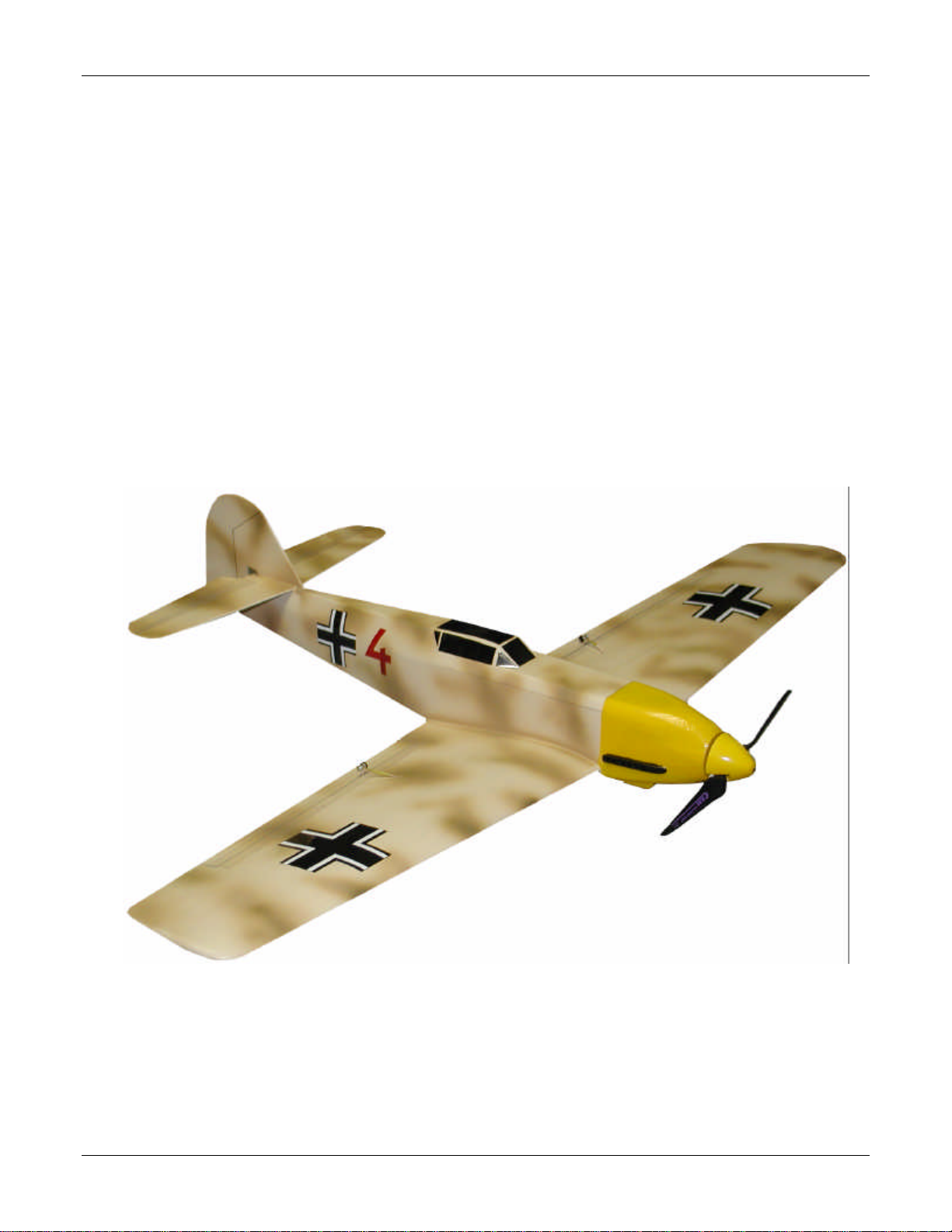
Laminate the ply hatch hold downs together, using the edges
to provide proper alignment. Glue in one of the magnets.
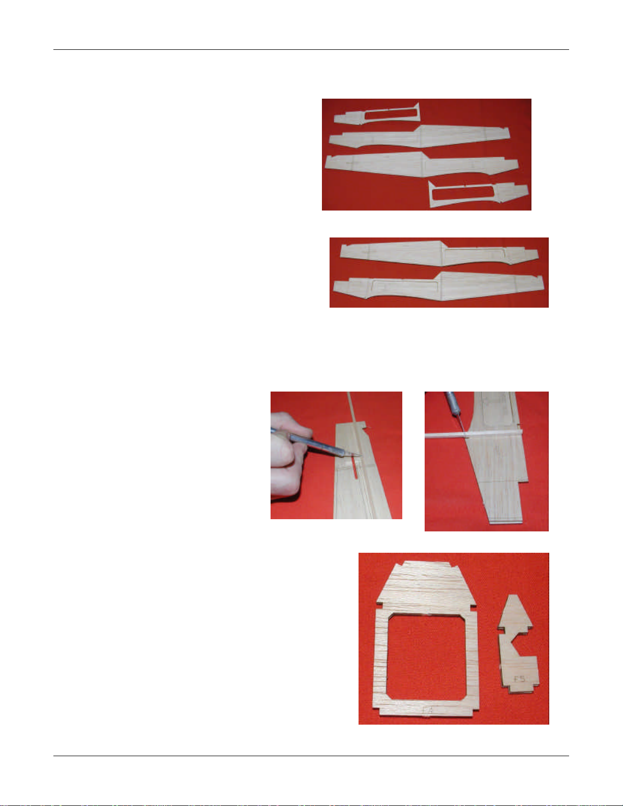
The last item to laminate is the firewall. Before you begin, trial
fit these two parts. They are made so that they fit the motor very
tightly, and the differences from cut-to-cut with the laser may
make for slight differences in size.
You can ensure proper alignment by using the motor to line up
the screw and bearing holes. Take care that you don’t glue the
motor in – it’s not easy to get it unglued.
Place the circular firewall doubler (ply, with small “ears”) on the
motor. Apply a thin coat of medium CA. Place the larger main
firewall in place, and screw it down to the motor. This will
ensure perfect alignment. Refer to Photo 13.
Remove the motor from the firewall after the glue has cured.
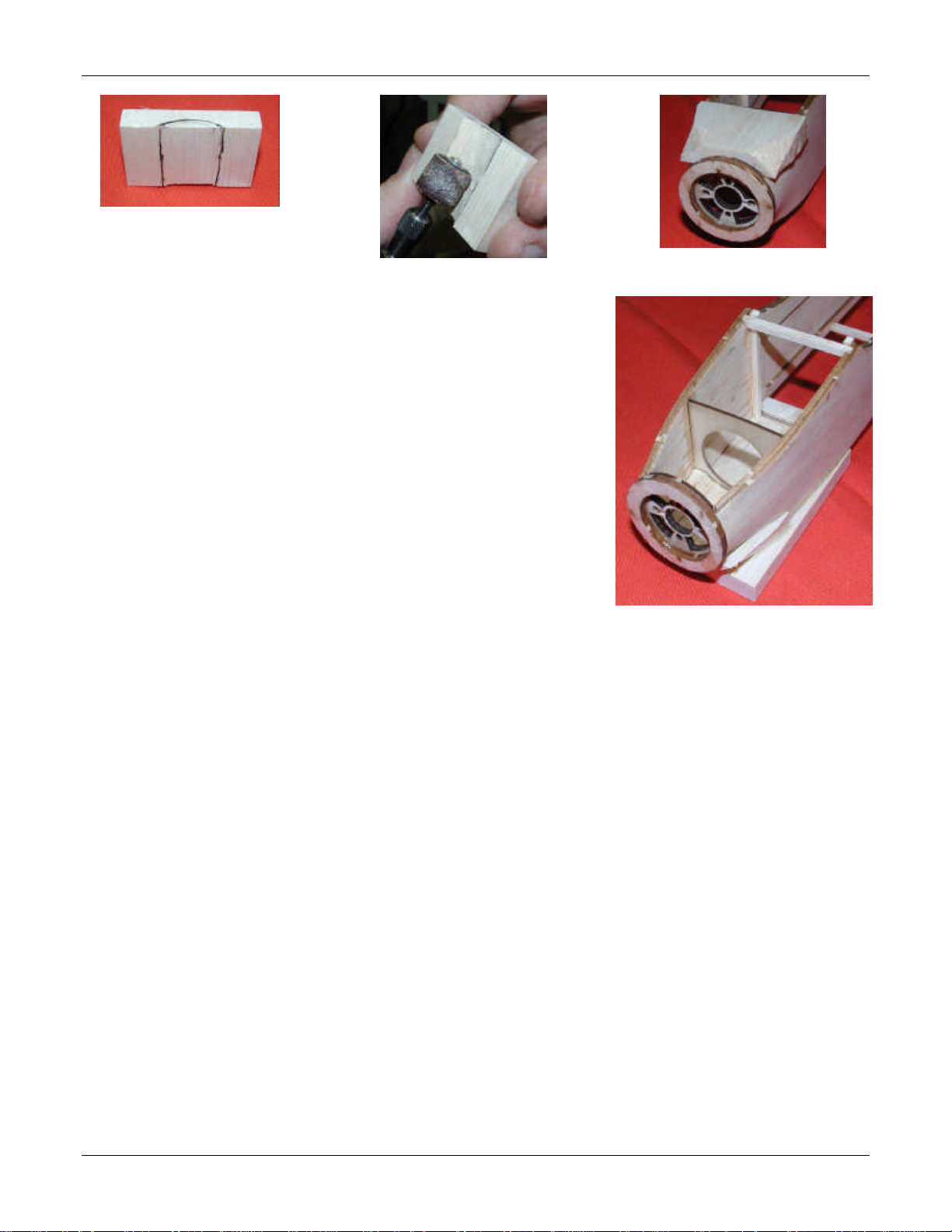
13) Glue the hatch hold down assembly into the fuselage. This will help to solidify
the fuselage somewhat.
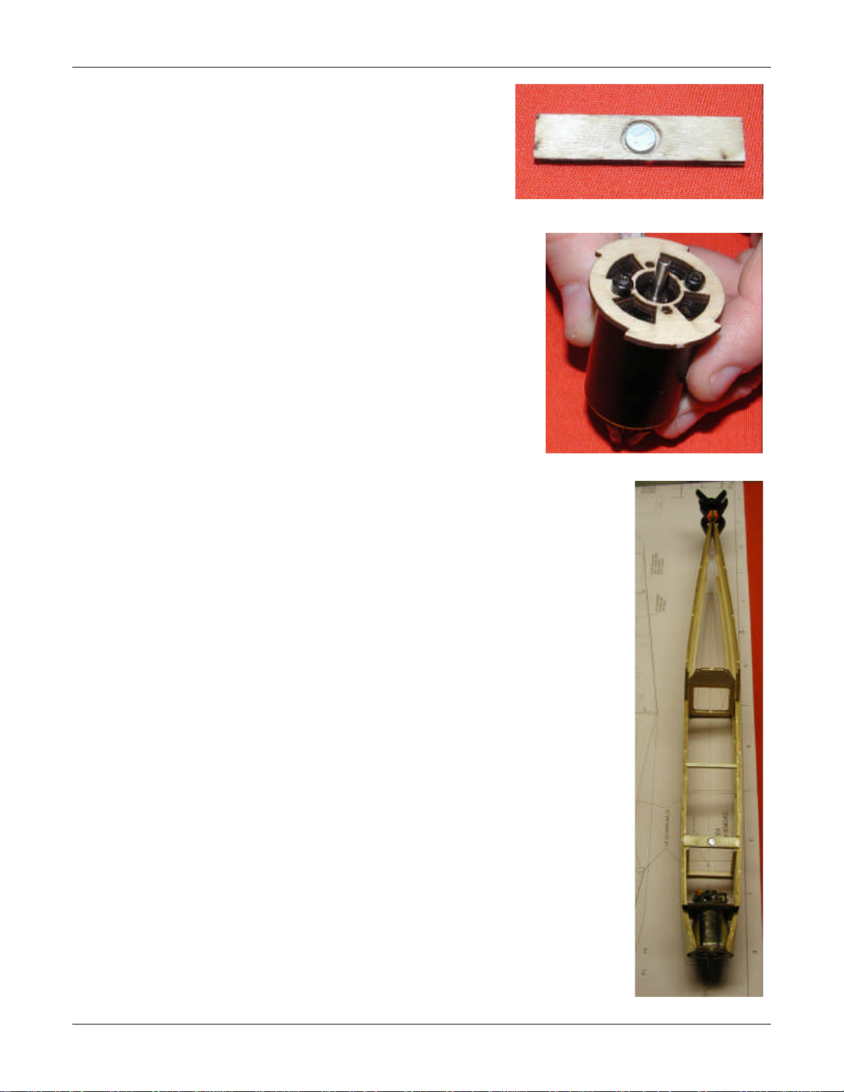
14) Pull the fuselage tail together. Verify that you do not introduce a twist to the
fuselage as you do this, and glue in place with thin CA. Use a clamp as shown
in Photo 14, using the top view on the plans to verify straightness.
15) Insert former F5 at the place noted on the fuselage sides. Make sure that you
have the notch in the side of the former on the left side so as to provide an area
for the elevator pushrod to exit later. When you are sure of alignment, use thin
CA to glue it in place.
If you are building your Blitzer for rudder and elevator, the former will be
opened in a later step to make clearance for the rudder pushrod.
16) Use some 1/16” scrap balsa across the front and rear of the servo tray to
beef it up a little. Install the servo tray immediately behind F4 on the
top of the rails extending to the back. BE CAREFUL NOT TO GLUE
THE SERVO TRAY TO THE SIDES, ONLY TO THE RAILS!
17) The firewall will now be mounted in place. If you were careful in
earlier steps, the correct right thrust angle will be automatic. It should
be about 2 degrees. F3 will set the angle properly for you.
It helps a lot to have an extra set of hands at this point. One person should
hold the balsa around the firewall while the other glues it in.

Blitzer Assembly Manual
Page 7of 21
Photo 15
Photo 18
Photo 16
Photo 17
OK, here is how to do it: Moisten front 3” of the fuselage
sides. Wait about 5 minutes, bending slightly from time to
time and adding more water until the wood is fairly flexible.
Use a heat gun to speed up the process.
Hold the firewall in place with the doubler wrapping against
F2 and the outer fuse side against F1. Tightly pull it around
completely and tightly. While it’s being held, have your
helper put drops of CA to lock it into place. Take care to
insure that the sides are centered on the recessed area as
shown in Photo 15.
18) Sand the rear bottom of the fuselage with a block so that any
excess wood is removed and the bottom is flush. Glue a 1”
long piece of 1/8” square to the bottom sheet at the indicated
position.
Attach the bottom sheeting to the rear fuselage. Align the
leading edge of the sheet so that it lines up with the front side
of F4.
19) Starting from the back, pull the rear turtledeck sides down to
F5 and glue it in place as you go. Slice a V notch into the
doubler forward of F4. Bend the turtledeck down to F4 and
glue it. Glue the sliced line at the top of the
Add a 1/8” square stringer
as far back as possible
(ending about 1” in front
of F5). After this is
installed, sand off the top
of the turtledeck until you
get it perfectly flat across
the top. This means all
the ash from the laser
cutter is removed as
shown in Photo 18.
20) Trim the smallest balsa
block to enable it to fit
between F1 and F3 (it is
provided slightly oversize
so you can get a perfect fit
for your model). In order
to accomplish this, you
will also need to notch it
slightly as shown in Photo
19 to provide room for the
motor and to allow it to fit
around F2.
Glue the block in place, then roughly trim it to the front as shown in Photo 21.

Blitzer Assembly Manual
Page 8of 21
Photo 22
Photo 19
Photo 20
Photo 21
21)Add the two nose rings to the front of F1, carefully centered.
22) Glue the larger block to the top. Note that the block for the top
side has square ends; the block with the angled ends is the chin
block.
It’s now time to set the fuselage aside until we are done with the wings.

Blitzer Assembly Manual
Page 9of 21
Photo 27
Photo 23
Photo 24
Photo 25
WING ASSEMBLY:
The Blitzer wings have no main spar as you are commonly accustomed to seeing. Instead, this wing
design derives it strength from the monocoque wing skins. The “spars” that we will be installing provide
alignment and filler but no significant strength.
23) Identify and remove all wing parts for the each wing. The skins say “LEFT” and “RIGHT” on them.
You will have three pieces for the bottom and two for the top, plus seven ribs R1 to R7.
24) Tape the large bottom wing sheets
tightly together, with the tape on the
outside surface. The bottoms are
identified by having laser-etched
printing on them. The inside surface
is the one which has the position of
the ribs drawn on it. Hold them
down flat against a table surface or
such, and run a thin bead of thin CA
into the butt joint.
25) With the wing skin still laying flat
with inside surface down, lightly
sand the surface of the wing as shown
in Photo 23.
26) Add a 1/16” x 1/8” strip on the
position of the main spar from wing
tip to root. Put another piece to at the
edge of the aileron from the “inside”
edge of R6 down to R2. This will
give you panels as shown in Photo
24.
27) Install each rib except R1 in the
appropriate place. Glue in place with
thin CA on the portion from the main
spar toward the trailing edge.
Your wing will now look like Photo
25.
Note how the bottom leading edge is above the
wood by a significant amount. While this wing is
not as easy to build as a flat-bottom would be, the
difference in performance is well worth the small
increase in building time.
28) Carefully yet firmly “roll” the wing so that the
bottom edge is flush against the ribs. Glue the ribs
down one at a time. I found it easiest to start
gluing with R4, then R3, then R5, etc. until done.

Blitzer Assembly Manual
Page 10 of 21
Photo 26
Photo 27
Photo 28
29) Sand a bevel to the wing skin at the
leading edge so that it makes the top
curve smoothly into it, as shown on the
plans “typical wing cross section” view,
and in Photo 26.
Do the same sort of thing on the trailing
edge between the ailerons and R1, and
R6 and R7. Note that the trailing edge
angle is much flatter than the leading
edge.
Cut ¼” out of R2 to allow the servo lead
to pass into the area between R1 & R2.
30) Set the wing on a flat table top with a ¾” block under the wing tip, and the square at the root. Use the
square to set R1 vertical as seen in Photo 27. Glue R1 in place at this angle.
31) The wings are built without washout, though a small amount (1/8” or less) is acceptable. The instructions
that follow are for building it with none.
With the trailing edge flat on the table, place the top wing skin aligned at the ailerons. Carefully tack the
trailing edge together, then follow by CA-ing it firmly. Next, lift the leading edge and put medium CA on
top of each rib up to about the peak of the camber, then fold the skin down on top of it and hold firmly.

Blitzer Assembly Manual
Page 11 of 21
Photo 31
Photo 32
Photo 29
Photo 30
Photo 33
32) After this cures, do the same thing to the forward half of the ribs. After this cures, clamp together the
leading edge as shown in Photo 29.
Glue the leading edge, making sure
that the seam is sealed closed.
33) With a long sanding block, sand the
wing panel to achieve a smooth,
uniform airfoil across to entire span
as shown in Photo 30. Note that this
will cause the trailing edge to thin
down to about 1/32” when done
properly.
34) Trim and sand both the root and the
tip with a sanding block so that the
skins are flush with the ribs. This
will allow us to join the panels to one
another with proper dihedral, and to
fit wing tip blocks.
35) Trim the ½” x 1” x 5” block to the
shape found on the template.
Position the block on the wing tip
such that it covers it completely. While holding it in
position, put a couple drops of CA on the joint to lock it
into place.
36) With a sanding block and medium coarse paper, sand
the top and bottom of the wing tip block to make it
conform to the airfoil as shown in Photo 32. Follow
that by rounding the edges to give a smooth contour as
shown in Photo 33.

Blitzer Assembly Manual
Page 12 of 21
Photo 35
Photo 36
Photo 37
Photo 34
Photo 38
37) Tape the wing panels together at the root with the
bottom edges aligned as shown in Photo 34. The tape
should be on the bottom edge.
38) Set the wing panels on a flat table with the tips each
blocked up ¾”. Open the joint at R1 and epoxy them to
one another, then set them back down on the blocks.
TAKE CARE TO ENSURE THE WINGS GO
TOGETHER IN PROPER ALIGNMENT!
39) Once the epoxy has cured, remove the tape from the
bottom of the wing. Sand the root joint of the two
wings so the edge is smooth. Measure a piece of the
fiberglass tape so it is a little longer than the bottom of
the wing. Center it on the bottom of the wing, and use
thin CA to glue it down. See Photo 35.
The CA will wick into both the wood and cloth. After
you have attached it, spray with accelerator –
sometimes large amounts of CA don’t cure well.
Avoid the fumes – this could get pretty warm and put
out a lot of noxious gas.
40) Trim the excess glass tape from the LE and TE. Lightly
sand the glassed area to blend the edges into the balsa
smoothly.
41) Glass the top wing joint as you did the bottom.
42) Cut a hole in the area between the root rib R1 and R2.
This hole will be used to thread the servo lead through
later.
43) Now it is time to cut out and finish the ailerons. Trim the
ailerons so they fit within the cut-outs in the wings.
44) Mark the aileron 1” from the root as shown in Photo 37.
Cut out an area ¼” x 1/16” to accept the control horn. The
horns extend out the bottom of the wing, and the control
horn is angled a bit so you will need to cut the notch at an
angle so it fits properly as shown in Photo 38.

Blitzer Assembly Manual
Page 13 of 21
Photo 39
Photo 40
Photo 41
45) Put the aileron in its proper place, and tape there with
packing tape on the bottom of the wing. Lay the wing
on the edge of a flat table and sand it so that it
matches the rest of the wing properly. Apply tape to
the top side of the wing, then remove it from the
bottom side.
46) Notch the wing edge where the control horn is in the
way. Cut the notch so that the aileron may bend all
the way down (about 30º).
47) At this point we want to thread the servo lead into the
wing so that it is available inside the fuselage later.
It’s much easier to do this now than it would be after the wing is joined to the fuse.
Remove the servo connector from the leads. Note the orientation of the contacts in the housing. You will
need to reassemble it properly later.
48) Make a hook in a short (6” or so) length of light piano
wire. Insert the piano wire through the hole you made
earlier (Photo 36) out to the aileron hole. Loop the
servo lead around that hook and tape it to hold it fast.
You should now have it as shown in Photo 40.
49) Pull the servo lead back out of the wing. Restore the
connector to its prior condition, and repeat for the other
wing.
50) Place a small scrap of 1/8” square balsa into the wing
as shown in Photo 41. This will serve to level the area
where the aileron servo will fit. Insert the servo
loosely.
51) Hook up and turn on your receiver and transmitter. Set
your radio system up with neutral aileron trim and the
stick in center, using a Y connector to attach both
servos to Channel 1. Adjust the position of the output
arms on the servos so that both arms are either
perpendicular to the wing bottom, or so that they are
slightly (1 tooth) toward the leading edge from center.
It is important that both are the same!
52) Remove the excess control arms and fit the servo down
against the 1/8” square stop you made above.
53) Drill the hole in the aileron control horn to that it
accepts the Micro EZ connectors. Use a sharp bit and drill carefully so as not to damage the wood. A
spare horn is included in the laser cut sheet just in case.
54) Insert the pre-bend end of the aileron pushrod into the innermost hole on the servo output arm. Install the
EZ connector into the aileron horn and assemble as shown in Photo 42.

Blitzer Assembly Manual
Page 14 of 21
Photo 42
Photo 43
Photo 44
Photo 45
Photo 46
55) Sand round the leading and trailing edges of the sides
and center support of the radiators. Install the two
outside ones to the bottom of the wing and glue in
place. Photo 42 shows this.
56) Trim the center support so that it clears the servo yet
still provides support. Sand round the leading and
trailing edges of the radiator bottom, then attach the
center support to it. Photo 43 shows a center support
before and after the fitting.
57) Glue the center support to the radiator bottom, then the
sides to the bottom. DO NOT glue the center support
to the wing itself. In the event of a servo failure, you
will need to neatly slice the sides, but you don’t want to
slice the center piece (it’s hard to do neatly – know how
I learned that?). If you wish, you may place a small
dab of thick CA to hold the servo in place. It is up to
you and how closely you fit the support to fit the servo.
58) Fit the wing to the fuselage now using epoxy to glue
them. Make sure that they fit snugly, and that the
fuselage sides are vertical when the wings are level.
59) Fit the chin block to the motor mount and wing leading
edge, removing small sections as shown in Photo 46 to
make it fit both parts. The wing/chin joint will
probably require a little putty to get a smooth finish.
60) Carve and sand the chin block to shape.
61) Using the side view of the plans as a guide, use your Dremel tool with a sanding drum to open a passage
for air in the chin block. The hole should have the front and rear angled so as to permit the easy flow of
air into the fuselage. Do not cut into the wing.
62) Round off the leading edges of the air scoop now.

Blitzer Assembly Manual
Page 15 of 21
Photo 47
Photo 48
63) Mount the air scoop sides at a slight angle as shown by the
front section A-A on the plans, and as seen in Photo 47.
Widen the hole in the chin block until it is smooth against
the sides.
64) Use a piece of scrap 1/16” sheet from the kit to make a
bottom cover for the air scoop. Glue it in place, then sand it
to fit. Round the edges.
65) Using a long bolt (or by mounting the motor), attach the
spinner plate to the front of the fuselage.
66) Sand everything smooth as shown in Photo 48 in preparation
for application of filling putty

Blitzer Assembly Manual
Page 16 of 21
Photo 49
Photo 50Photo 50
Photo 52
Photo 50
Photo 54
Photo 50
Photo 53
HATCH ASSEMBLY:
67) Laminate one piece of C1 to C2 with the bottom edges
flush.
68) Attach all pieces of C1 and C1/C2 to the hatch floor. Attach
two pieces of C4 behind C2 as shown in Photo 49.
69) Insert a 4-40 nut into the hole at the front of the hatch floor,
another into the hole in one C3, and a magnet into the hole
in another C3.
70) Bevel the bottom edges of the hatch sides so that they are flush against the top of the fuselag. Place the
hatch on the fuselage, then position the hatch side panels in place and glue. Refer to Photos 50 and 51.
71) Sand the top sides of the hatch so they are straight across.
Attach the top front section and canopy top. Sand the edges
of these to bring them flush into the fuselage.
72) Fit and glue the C3 containing the nut into the back end of
the hatch. This will require some beveling with the sanding
block in order to make a good fit. Sand the bottom to ensure
a flat area to mate to the fuselage. Refer to Photo 53.
73) Fit the C3 containing the magnet into the corresponding part
of the fuselage. When you are ready to glue it in, put a
small sheet of clear plastic kitchen wrap between the two
C3’s. The magnet
will hold it tightly in
place. When you
glue, it will not stick
the hatch to the
fuselage.
Photo 51

Blitzer Assembly Manual
Page 17 of 21
Photo 55
EMPENNAGE ASSEMBLY:
74) Tape the two elevator halves to the stabilizer so that they are in the tips align properly. The tape should
be on the top side (signified by the center line on the stab). Insert the 1/16” ply joiner between them.
You may need to very lightly sand it to get a good, snug fit.
75) Using thick CA or epoxy, glue the ply joiner to the balsa panels. Note that the balsa is much thicker –
this allows you to make a good fillet at the joint. Be careful not to glue the elevator to the stabilizer.
76) When the glue has cured, trim the tape back about ¼” from the edge of the wood. Sand the outside
perimeter of the elevator and stab to round the edges.
77) While you have this taped together, drill the holes which will mount the elevator control horn. Remember
that the horn is on the bottom left side. It should be angled so that it is not quite parallel to the cut-out
section between the elevator halves, as close as possible to the center. You will have one whole in ply,
the other in balsa.
78) Remove the tape. Sand a bevel on the elevator portion to about a 30 degree angle. This will allow the
elevator (which will be hinged at the top) to bend down.
79) Tape the vertical fin and rudder together, then drip some thin CA into the joint. Remove the tape and
sand the edges round. Do not sand the places where this will be glued to the fuselage or elevator.
80) Using the building square, line up the stabilizer
with the fin and glue in place. Use the center
line on the stab to position the fin properly. It
should be centered on the line.
81) Set the fuselage on a table top, using blocks to
make sure the sides are vertical. Set the
empennage assembly onto the model, and tack
glue the front to the top of the fuse. Using cans
or large squares, make the rudder vertical, as
shown in Photo 55.
82) Ensure again that the wings are level (same
dihedral) and that the tail is level (same
measurement right and left). When everything is
lined up, carefully glue this together. Take care
to ensure that the stab is against the wood saddle.
83) As is customary, hold the fully assembled airplane in your dominant hand and “fly” it around the room,
making airplane noises. It is acceptable to strafe the household pets and any other airplanes in your shop
should you find this necessary.
We are almost there!

Blitzer Assembly Manual
Page 18 of 21
Photo 56
Photo 57
Photo 58
FINISHING:
Before applying finish, fill all dings and hollows with a light spackling compound and sand them out. On
the Blitzer, the following areas are intended to be filled for best finish:
Around the nose rings, blending into the fuselage (Photos 56 & 57)
Behind the chin block, blending into the underside of the wing (Photo 57)
At the rear of the wing, blending into the fuselage (Photo 58)
Around the hatch, filling the gap (not shown)
The keys where the under-wing radiators attach together (Photo 59)
You may finish your Blitzer with any type of finish you desire. Our favorite finish (we’re a little old-
fashioned) is to spray it with several coats of clear Sig Nitrate Dope, wet sanding between coats. After
this, we spray on appropriate colors to make the finish you desire. When using flat finishes, we like to
use 3M Magic Tape (office supply cellophane with matte finish). On glossy finishes packing tape works
well.
If you desire to use a plastic covering, please use the lightest you can. We recommend Solarfilm Lite
(SoLite) or Nelson.
Cover the model from the bottom to the top, rear to front. This way the overlaps will give a better top
view and prevent the wind from peeling any loose areas back. Cover the control surfaces, then use a ½”
wide strip of covering as a hinge, then cover the main surface. For the ailerons it is best to seal the gap,
however doing so may make the controls stiff. You may want to disconnect the servo output arm to make
covering the ailerons easier.

Blitzer Assembly Manual
Page 19 of 21
Photo 59
CONTROLS:
If your transmitter has expo, set the ailerons to at least –40
starting out. As you gain experience with the Blitzer, you may
reduce this.
Set the elevator to –10 expo for starters.
84) Install the elevator pushrod into the fuselage from the hole on
the left rear fuselage toward the servo. The Z-bend end gets
inserted into the servo arm in the middle position. Put the EZ-
connector into the farthest-in position on the elevator control
arm. Install the arm on the servo and use the radio to set the
servo to the neutral position. When done, tighten the setscrew on the EZ connector. Trim off all except
about 3/8” of pushrod to leave a little adjustment.
It doesn’t take a lot of elevator control. 3/16” up and 3/16” down travel is adequate.
85) Mount the receiver with servo tape or Velcro inside the cabin. Thread the antenna out through the hole on
the bottom of the fuselage. Tape it into place where it exits, and at the very back of the plane. This will
keep it out of your way when flying.
86) Attach the ESC to the motor, then mount the motor, prop and spinner. Leave a small gap (about 1/32”)
between the spinner and the fuselage.
87) Look inside the fuselage and you will see two arrows on the fuselage sides indicating the balance point.
Balance the airplane at this point by sliding the battery pack fore/aft. When you have achieved a good
balance, Velcro the battery pack in place.
It is our experience that the batteries will need to be as far forward as possible due to the short nose of this
plane.
Table of contents