Thishomestandbygeneratingsetisinherentlyprotectedby
designagainstdamagetothegenerator,transferswitchandfeeder
conductors(ifproperlysized).Ifa shortcircuitorlargeoverload
occurs,generatoroutputdropstozeroandnodamageresults.
GROUNDING
WARNING Failuretogroundthegeneratingsetcould
resultinseriouselectricalshock.
Connecta #8wireorlarger(followingapplicable
codes)between:
1.
A separategroundpipeorrodpenetratinginto
moistearth,and
2.
thesolderlessconnectorwhichislocatedontop
ofthegeneratorfortheremotestartmodelsand
onthestart-stopcontrolboxfortheelectricstart
models.
WARNING ^TheNationalElectricalCode(NEC)requires
thatallseparatelyderivedACsystemsbe
groundedperArticle250-26.Manufacturerhasaddeda bonding
jumperperarticle250-26(a)fromthenoncurrentcarryingmetal
partstotheconductortobegrounded.Manufacturerdoesnot
supplytherequiredgroundingconductororgroundingelectrode
becauseitwouldbeimpossibletocovereveryexceptionandall
localcoderequirements.SeeyourlocalcodesandtheNECman-
ualforthepropergroundingforyourapplication.
Asa generalrule,donotuseelectricalequipmentinwetordamp
areas.
Forconstructionsites,additionalrulesapplytoportable
alternatorswhenusedonconstructionsites,fromNEC,OSHAand
statecodes.Itistheresponsibilityoftheconsumertomeetthese
requirements.
GASOLINE
TANK,
HOLDER
AND
HOOD
Instructionsforinstallationandconnectionsforgaseousfuelare
includedwiththegaseousfuelpackage.
Theremotestartgas-gasolinemodelincludesagaso-
linetankbracketandtankhoodformountingthe
gasolinetankontherearofthecompartment.Usethe
followinginstructions.
1.
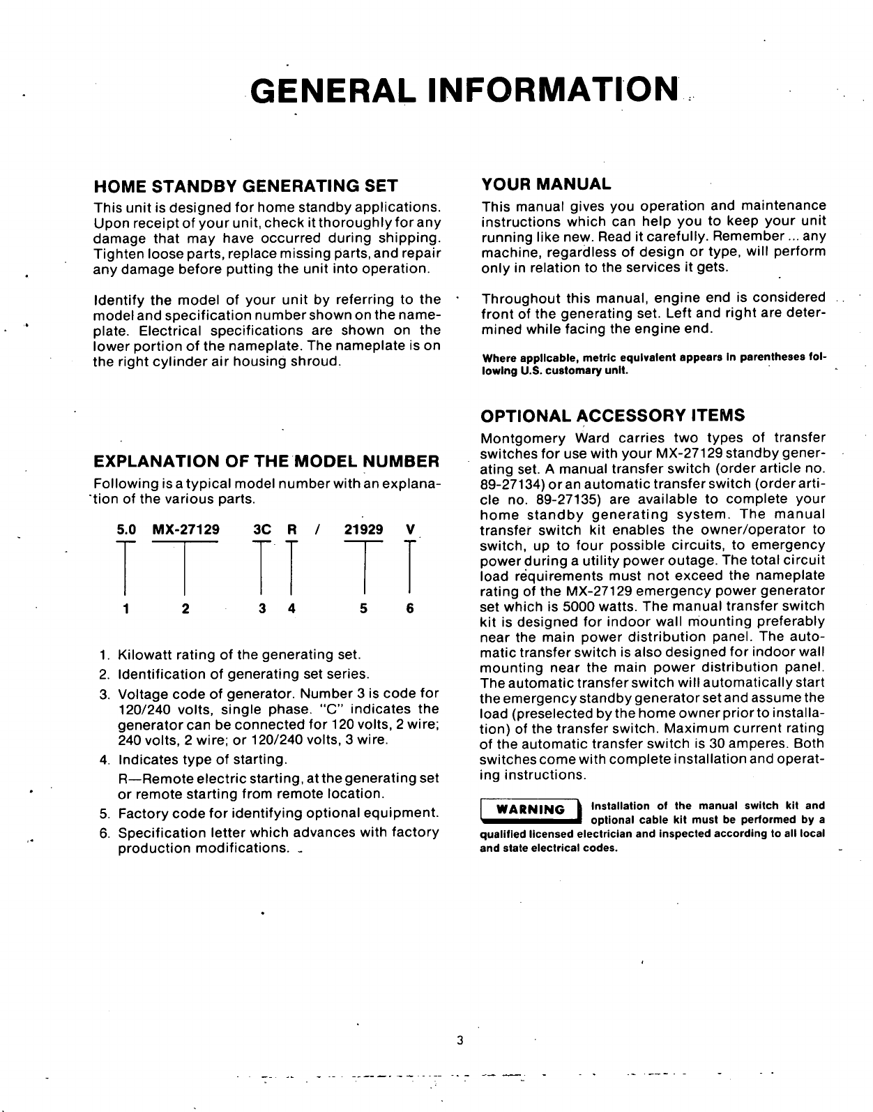
Facingtherearofthecompartment,removethe
bottom,
middlelagboltandwasher.SeeFigure4.
Donotdiscardtheboltorwasher.
2.
Mountthegasolinecanbracketwiththeonelag
boltandwasherjustremoved(fromStep1)and
twohexhead5/16-18screws,flatwashers,lock
washerandnutsasshowninFigure4.Holesin
thepanelarealreadydrilledforthetopscrews.
3.Placethegasolinetankinthetankbracketsothe
tankcapisontheleftasyoufacetherearofthe
compartment.
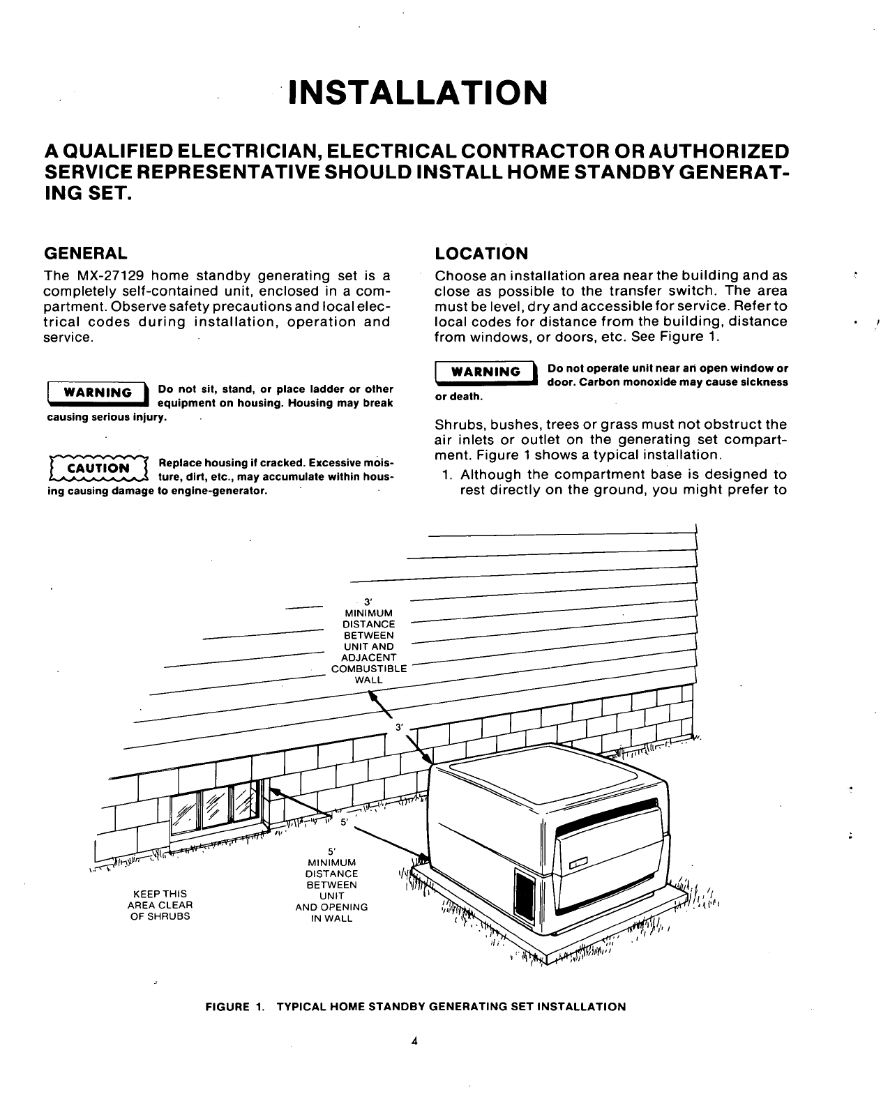
4.
Connectthefemaleconnectorontheendofthe
suppliedfuellinetothetankcapmaleconnector.
Pullthefemaleconnectorsleeveback,insertand
TANKHOLDER
5/I6-IN.
SCREWS,FLAT
WASHERS.LOCKWASHERS
ANDNUTS.
MIDDLELAGBOLT
ANDWASHEROF
COMPARTMENTREAR
FIGURE4.INSTALLATIONOFGASOLINE
TANKHOLDER
holdoverthemaleconnectorandrelease.See
Figure5.
Besuretoconnectthefemaleconnectoronthefuellinetothe
tankcapbeforeroutingfuellinetofuelpump.Otherwise,you
mightaccidentallyplacetheconnectorontheinsideofthe
compartment.
FEMALECONNECTOR
FORGASOLINELINE
(NOTESLEEVEIS
MALESt.PULLEDBACK)
CONNECTOR
TANKCAP
5.
6.
7.
8.
FIGURE5. CONNECTIONOFFEMALE
CONNECTORTOTANKCAP
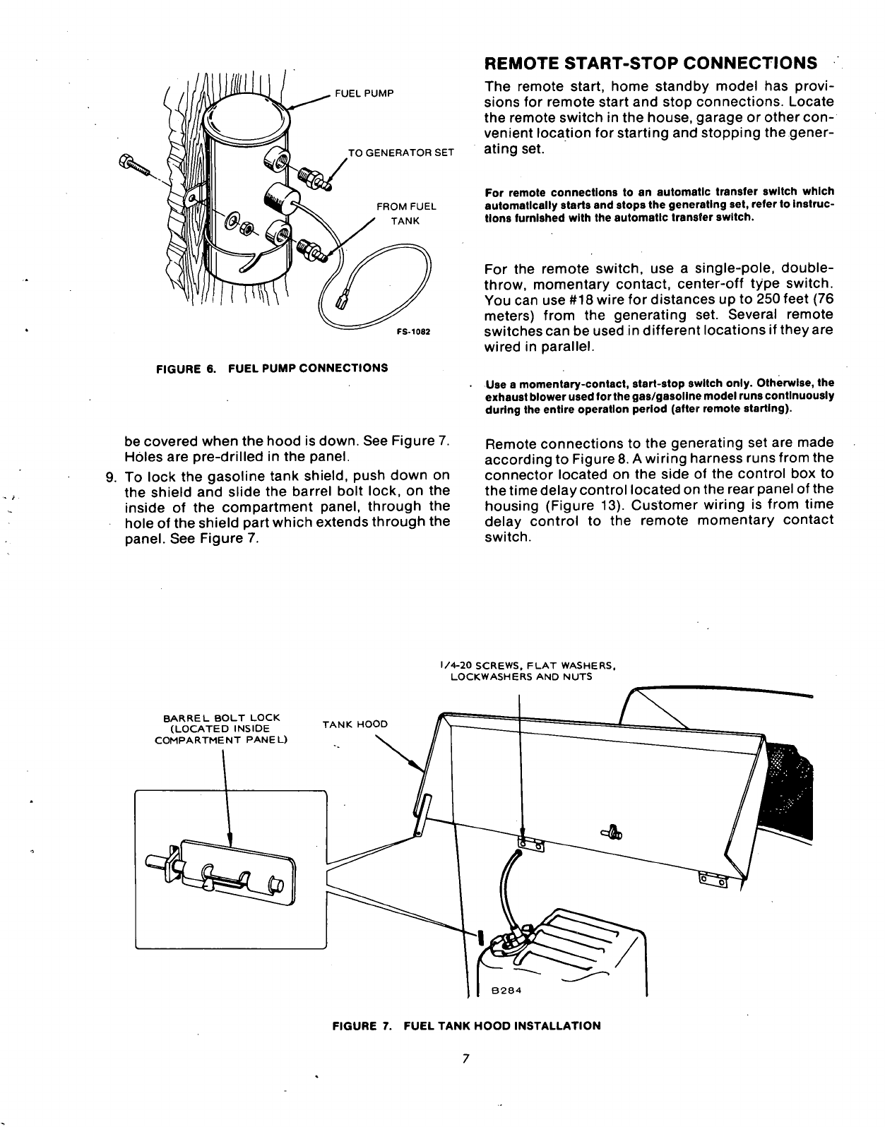
Runthelooseendofthefuelline(opposite
con-
nectorend)throughthesmallholeontherearof
thecompartment.Figure6 showswhereline
entersinsidecompartment.
Slipthehoseclampoverthelooseendofthefuel
line(nowinsidethecompartment).SeeFigure6.
Connecttheendofthelinetotheunusedconnec-
toronthefuelpump(Figure6).Movetheclamp
neartheendofthefuelline(overfuelpump
connector).
Installthegasolinetankhoodwithfour
1/4-20
screws,flatwashers,lockwashersandnuts.
Mountthehoodsothehingesfacedownandwill