Montigo Rio DX Instruction manual

www.montigo.com
Installation Operation & Maintenance Manual
Check local codes and read all instructions prior to installation.
XG0512 Canadian Heating Products Inc. Langley, BC V4W 4A Montigo Del Ray Corp. Ferndale, WA 98248 120507
Rio DX
Cast Stove
Rio DX Cast Stove
HL38DF-PFC Shown
For Your Safety:
Do not store or use gasoline or other flammable vapors and liquids in the
vicinity of this or any other appliance.
Safety Notice:
Glass doors on gas fireplaces are extremely hot while the fireplace is on and remain
hot even after the fireplace has been turned off. Safety screens are available and
can reduce the risks of severe burns.
®
C US
Warning:
Improper installation,adjustment,alteration,serviceor maintenancecan cause
injury or property damage. Refer to this manual. For assistance or additional
information consult a qualied installer, service agency or the gas supplier.
Warning:
What to do if you smell gas
• Do not try to light any appliance.
• Do not touch any electrical
switch; do not use any phone in
your building.
• Immediately call your gas
supplier from a neighbor's
phone. Follow the gas supplier's
instructions.
• If you cannot reach your gas
supplier, call the re department.
• Installer: Leave this manual
with the appliance.
• Consumer: Leave this
manual for future reference.

Page 2 Part No. XG0512
Rio DX Cast Stove
Introduction
About this Stove:
Thank you for purchasing the Rio DX Cast Stove, and choosing a
Delray Gas Product. This Rio Stove features a 28,000 BTU double
burner with embers, and a hi-lo adjustable control. .
This Stove is certified for use with Montigo Direct Vent Components.
The Rio DX Stove is certified as a heating appliance by CGA and
AGA tothe Vented Gas Fireplace Heater standard (ANSI Z21.88-
2005 · CGA 2.33-2005) and is rated for:
Natural Gas 28,000 BTU/H Maximum Input
20,500 BTU/H Minimum Input
Propane 28,000 BTU/H Maximum Input
20,500 BTU/H Minimum Input
How to use this manual:
This manual covers installation, operation and maintenance. Light-
ing, operation and care of this fireplace can be easily performed by
the homeowner. However, all installation and service work should be
performed by a qualified or licensed installer, plumber, or gasfitter
who is qualified or licensed by the state, province, region, or govern-
ing body in which the appliance is being installed.
This manual covers all versions. Sections which are specific to a
particular version are marked with a symbol, plus the appropriate
model number.
Warranty and Installation Information:
The Montigo warranty will be voided by, and Montigo disclaims any
responsibility for, the following actions:
Modification of the fireplace and/or components including Direct-
Vent assembly or glass doors.
Use of any component part not manufactured or approved by
Montigo in combination with this Montigo fireplace system.
Installation other than as instructed in this manual.
Consult your local Gas Inspection Branch on installation require-
ments for factory-built gas fireplaces. Installation & repairs should be
done by a qualified contractor.
Installations in Canada must conform to the current CAN/CGA
B-149.1 and .2 Gas Installation Code and local regulations. If the
optional air-circulating fan kit is installed, it must be electrically
grounded in accordance with CSA C22.1 Canadian Electrical Code
Part 1 and/or Local Codes.
Installations in the USA must conform to local codes, or in the
absense of local codes to the National Fuel Gas Code, ANSI
Z223.1-1988. If the optional air-circulating fan is installed, it must be
grounded in accordance with local codes or, in the absence of local
codes, with the National Electrical Code, ANSI/NFPA 70-1987. See
Appendix A for replace installations within the State of Mas-
sachusetts.
Table Of Contents
Introduction............................................................................... 2
Installation
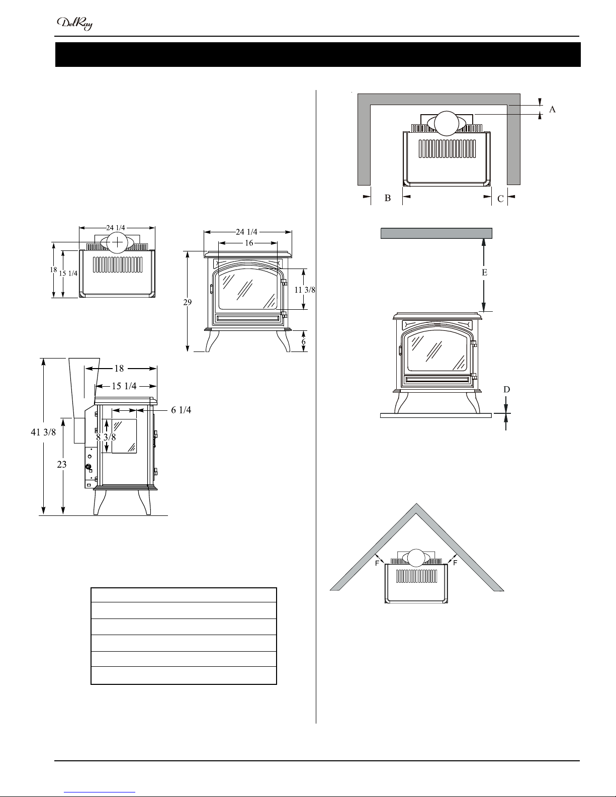
Choosing a Location ...................................................... 3
Installing the Gasline...................................................... 4
Direct Vent Installation ................................................... 4
General Requirements ...................................... 4
Terminations ...................................................... 4
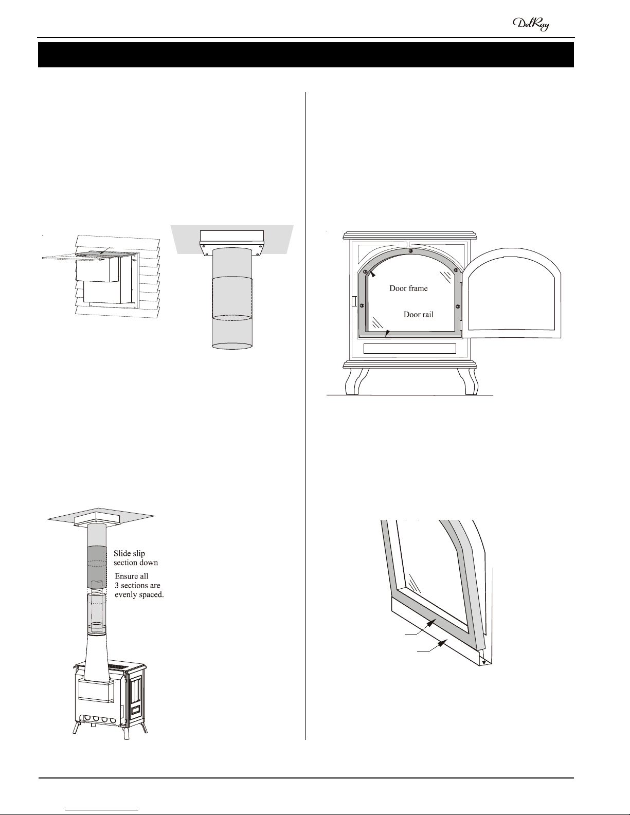
Horizontal(Top Vent Through-the-Wall) Installations6
Vertical (Top Vent Through-the-Roof) Installations. 7
Removing and Installing the Door.................................. 8
Installing the Logset ....................................................... 9
Wiring ........................................................................... 9
Operation..........................................................................10 - 12
Maintenance.....................................................................12 - 13
Warranty.................................................................................. 14
Appendix
A. Termination Locations.............................................. 15
B. Accessories and Vent Components..................16 - 17
CAUTIONS
Due to its high operating temperatures, the appliance
should be located out of traffic & away from furniture and
draperies.
Children and adults should be alerted to the hazards
of the high surface temperature, which could cause
burns or clothing ignition.
Young children should be carefully supervised when
they are in the same room as the appliance.
Clothing or other flammable materials should not be
placed on or near the appliance.

Page 3
Part No. XG0512
Rio DX Cast Stove
Choosing a Location
The fireplace may be installed in any location that mantains clear-
ances to air conditioning ducts, electrical wiring and plumbing. Safety,
as well as efficiency of operation, must be considered when selecting
the fireplace location. Try to select a location that does not interfere
with room traffic, has adequate ventilation, and offers an accessible
pathway for vent installation. Refer to page 4 - Vent Installation for
more information.
The Rio's dimensions are shown below:
Installation
Figure 1. Stove dimensions.
Front View
Side View
When installing this stove in an alcove, the minimum clearance from
the top of the stove to a combustible surface is 42". (Minimum 1"
clearance must be maintained around the vent pipes.)
Figure 2a. Minimum clearances to combustible surfaces.
Top View
Clearances
The Rio DX Cast Stove's minimum clearances to combustible
materials are:
A - Back* 3 ½"
B - Control Side† 24"
C - Right Side 10 ½"
D - Floor 0"
E - Top** 44"
F - Corner*** 2"
* See diagrams below for explanation.
** Clearance from the top of the stove to a
combustible ceiling.
† Clearance may be reduced to 10 ½ only
when installing in a corner installation.
Figure 2b. Minimum 2" clearances to combustible surfaces for a
corner installation.***
***When installing the DXFS in a corner application, the clearances
may be further reduced to 2", only when an on/off/ remote/ or
thermostatic control is installed in an accessible location. If this
on/off/ remote/ or thermostatic control is not installed, then
the clearance of 10 1/2" must be maintained.

Page 4 Part No. XG0512
Rio DX Cast Stove
Direct Vent Installation
This section covers the installation of venting and terminations.
Installation Requirements
Rio Stoves are certified for use with Montigo Standard Series (4"
/ 7") venting components and approved Vent Kits (listed below)
Minimum 1" clearance to combustibles required for vent pipes
Use only certified Montigo vent components. (Use of other parts
will void the Montigo warranty, and may impede the operation of
the stove.)
All joints must be secured with a minimum of two screws per joint
Vent terminations must not be recessed in walls or siding
Horizontal runs must be supported by a minimum of two supports
per horizontal run. A minimum of one screw on each side of sup-
port is also required
Flex vent sections may be stretched up to 50% of their total length
(eg. a 24" section may be stretched to 36")
Maximum horizontal run for a flex section with no vertical rise is 3
feet.
Flex vent sections over 3 feet must fall within the limits set by the
venting graph and must have a minimum vertical rise of 3 inches
per foot of flex.
Venting components can be used in any combination of solid/rigid
Solid vent sections may be cut less than half way from the tapered
end
Venting components can be used in any combination of solid/rigid
pipe or flex pipe and in any orientation (Male connectors can face
in any direction)
Vent Terminations
Selecting A Termination Location
Choosing your vent termination location will help to determine whether
Installing The Gas Line
The gas line must be installed before completing the installation. Nat-
ural Gas requires a minimum inlet gas supply pressure of 5.5" W.C.
& a manifold pressure of 3.5" W.C. Propane Gas requires a minimum
inlet gas supply pressure of 11" W.C. & a manifold pressure of 10"
W.C. Provision must also be made for a 1/8" N.P.T. plugged tapping
and be accessible for test gauge connection immediately upstream
of the gas supply controls to the appliance. The stove is supplied with
a flexible gas connector which is factory installed. The gas valve is
located on the back of the stove as indicated in figure 4. It should be
attached to the gas line with an approved fitting, as required by the
applicable installation codes.
• Only use gas shut-o valves approved for use by the state, province,
region, or governing body, in which the appliance is being installed, or
as required by the applicable installation codes.
• Flexible gas connectors must not exceed 3 feet in length, unless it is
allowable within applicable installation codes.
Installation
Figure 5. Fireplace locations and vent terminations.
Note: After gas line is connected, each appliance connection,
valveandvalvetrainmustbecheckedwhileundernormal
operating pressure with either a liquid solution, or leak
detection device, to locate any source of leak. Tighten
any areas where bubbling appears or leak is detected until
bubbling stops completely or leak is no longer detected.
DO NOT use a flame of any kind to test for leaks.
During any pressure testing of the gas supply piping that excedes 1/2
psig (3.5 kPa), the appliance and its individual shutoff valve must be
disconnected from gas supply system.
When pressure testing the gas supply piping system at test pressures
of less than or equal to 1/2 psig (3.5 kPa), the appliance must be
isolated from the gas supply piping system by closing its individual
manual shutoff valve.
Figure 4. Gas line access.
Cautions:
Vent terminations can be very hot. If the termination is less
than 7 feet above a public walkway, it should be fitted with a
certied Montigo Heat Guard. (Part no. MTKOG)
Do not obstruct, or attempt to conceal, the vent termination.
These actions will affect the operation of the fireplace, and may
be hazardous.
In heavy snow areas, take extra care to prevent snow buildup
from obstructing the vent termination.

Page 5
Part No. XG0512
Rio DX Cast Stove
Installation Direct Vent
Top Vent Venting Runs
For the Rio Pedestal Stove there are two types of Top Vent (DV)
installations: A) Horizontal (Through-The-Wall) Installations and B)
Vertical (Through-The-Roof) Installations.
Allowable Vent Runs
Before you install any venting, you must determine whether the
venting run will be acceptable. Unacceptable venting can affect the
fireplace's combustion. Figure 8 shows various vent rises and the
corresponding number of 90° bends which can be made.
Figure 8. Venting limitations for top vent installations.
The minimum vertical rise for a Top Vent Installation is 29 1/2", which
allows 1 - 90° elbow and a maximum horizontal run of 10'. With
greater vertical rise, the number of 90° bends may be increased ac-
cording to the chart below. The total maximum horizontal run (HT) is
also shown, and the run between each elbow (Hx) may be any length,
as long as it does not exceed (HT).
Vent Rise1Max. # Max. Horiz.
(V) of elbows Run (HT)
29 1/2" (min.) 1 10'
4' 2 10'
5' 2 10'
10' 3 10'
15' 3 10'
20' 3 10'
25' (max.) See vertical vent section
1 Vertical rise is measured from the center of the stove's flue
collar to the center of the termination.
2See 'Through-the-Roof Installations'
Example:
If V= 12', the vent run may use up to 3 - 90° elbows.
If H1= 3', H2=2', and H3=3',
then HT=8'.
This would be an acceptable installation.
1. Ensure that the two long mounting brackets are facing the bot-
tom of the termination. (See inset). This will provide more heat
protection at the top of the termination, where temperatures are
highest.
2. Attach to the faceplate of the termination using four sheet metal
screws.
Installing Heat Guards over Terminations
MTKOG
Installing Terminations with Built-In Frames
11
11
1. Frame the termination opening to 11" x 11".
2. Fasten the termination to the studs using a minimum of 4
MTO-3F
Figure 7. Installing the heat guard.
Figure 6. Installing the MTO-3F Termination.

Page 6 Part No. XG0512
Rio DX Cast Stove
3. Install the first stove pipe onto the FST12 / FST14 ellipse sec-
tion (refer to Figure 9). Secure the pipe with at least two ½" hex
screws spaced approx. 3/4" from the joint. Slide the remaining
vertical stove pipes into place, without fastening them.
4. Cut the horizontal stove pipe (FST11) to length. Slide it and the
90°elbow and onto the vertical pieces of stove pipe. Slide the
Decorative Wall Plate (Part # FST07) onto the horizontal section,
making sure the unpainted side faces the wall.
Completing the Vent Run
5. Slide the stove back into position so the pipe protrudes through
the wall. Pull the flex forward and attach it to the termination (or
other vent sections, if necessary, to extend the vent run) with high
temp sealant. Run a bead of high temp sealant around the stove
pipe and push the termination on. Attach the termination to the
wall as shown on page 5.
Adjust the position of the stove pipes so thethat joints are all
equally spaced. Ensure that there is at least 1 1/2" overlap be-
tween each section.
Secure each stove pipe joint with at least three ½" hex screws
spaced approx. 3/4" from the joint (so that the brass ring will
cover both the joint and the screws).
Finishing
6. Now slide the Decorative Wall Plate against the hole, level it, and
secure using four screws.
7. Cover each joint in the stove pipes with a brass decorator ring.
The rings should cover the joint as well as the sheet metal screws.
Attach the ring using the black 3/8" screws provided. Make sure
the screw is facing the back of the stove. See Figure 11.
Installation Direct Vent
A) Through-the-Wall (Horizontal) Venting Option
The horizontal venting option requires an FSTK05 Vent Kit. Figure 9
shows the components which are used to attain different vent heights.
Additional stove pipe or Montigo Standard Series vent components
may be used to increase the vent run, as long as the run still falls
within the limits set out in Figure 8.
1- Vertical Rise is measured
from the center of the stove's
flue collar to the center of the
termination.
2-
A - Std. Stove Pipe (FST11)
B - 90° Elbow (MEL10MB)
C - Oversize Stove Pipe
(FST05)
D - Standard Termination
(MTO-3)
E - 5" stove pipe (F/F)
Figure 11. Installing the decorative brass rings.
Installing the Stove Pipe
1. Ensure that the intended pathway for the venting is clear.Try to
position the stove midway between two studs to avoid having to
cut them. Cut and frame a 10" x 10" hole for the termination.
2. First attach the inner pipe to the stove's flue collar using a bead of
high temp silicone. Attach the outer eliptical section as shown in
Figure 10. Secure it with four sheet metal screws.
Note: The Eliptical section (FST12 / FST14) is shipped with the stove
but boxed seperately.
Figure 10. Attaching the FST12 Eliptical Section.
Figure 9. Possible venting configurations using the FSTK05 kit.
Vertical Rise 29 1/2-
Vertical Rise 43-64"
Vertical Rise 64-79"
Vertical Rise 29 1/2"

Page 7
Part No. XG0512
Rio DX Cast Stove
Installation Direct Vent
11”
Ceiling box
MEXT-2
in position
11”
Figure 13c. Installing the ceiling box.
Figure 12. Vertical installation options. Left: straight vertical installa-
tion (no offsets).
B) Vertical (Through-The-Roof) Venting Option
When venting through the roof, use an FSTK04 Vent Kit. Additional
stove pipe or Montigo Standard Series vent components may be
used to increase the vent run, as long as the run still falls within the
limits set out in Figure 12.
Vertical Vent Requirements:
Vertical terminations (Part # MVTK-1) must be installed:
• minimum 2' above the highest point where the vent passes
through the roof
• minimum 6' from a mechanical air inlet
• minimum 18" from a parapet wall
Maximum vent height is 25 above the stove's flue collar.
(Note: Flame characteristics may change if the maximum vent height
is used.)
A maximum of two offsets (each offset has two 90° bends) may be
made. The total length of the offset(s) must not be more than 25% of
the vertical vent height, when measured from center to center of the
piping.
Example: Vertical vent height - 20 feet
25% of 20' = 5' max. offset allowed
2 - 2' offsets required = 4' offset
This vent configuration is acceptable.
Installing the Stove Pipe
Ensure that the intended pathway for the venting is clear.Try to
position the stove midway between two joists to avoid having to cut
them. Determine the ceiling box location. Measure a minimum of 6
1/4" between the centre of the pathway and the back wall as shown
in figure 13a. For corner installations, measure 24 1/4" between the
back corner and the intended pathway as shown in figure 13b. This
will maintain the stove's minimum clear-
ances as shown on page 3. Cut and
frame an 11" x 11" hole in the ceiling and
roof as required.
Install the ceiling box as shown in Figure
13c. Ensure that there is at least 2"
clearance from the bottom of the box
to the ceiling. Fasten in place with 2
screws per side.
Slide the MEXT-2 down into position so
the male end protrudes into the room
below the ceiling box as shown in Fig-
ure 13c and secure it temporarily with an
MSPXT-7 support plate and ring.
Measure the flex pipe (FST08) and cut it
to the required length. Install the second
collar onto the end of the flex. Attach
one end of the flex to the inner collar
of the MEXT-2, and secure it with three
screws.
Slide the decorative ceiling plate about
two inches down from the end of the
top section of stove pipe. Install the top
stove pipe onto the outer collar of the MEXT-2. Now slide the decora-
tive ceiling plate up against the bottom of the ceiling box and secure it
with four screws. Install the first spacer spring by sliding it up over the
bottom of the stove pipe.
Now slide the slip section (Part # FST05) up over the flex, overlap-
ping the top section at least half its length to keep the pipe out of your
Figure 13b. Determine the ceiling box location for a corner instal-
lation. To ensure that a 10 1/2" clearance is maintaned
the centre of the flue should be 24 1/4" from the back
corner.

Page 8 Part No. XG0512
Rio DX Cast Stove
Installation
Removing and Installing
the Door
Removing the door:
To access the glass door, open the outer doors on the front of the
casting. Remove the 5 nuts around the edge of the glass door, and
then pull the door outwards and upwards until it is clear of the door
rail.(See Figure 20).
Figure 20. Removing or installing the glass door.
Installing the door:
Slide the bottom of the glass door into the door rail. Be sure the door
is pushed all the way into the rail. See figure 21. Attach using the 5
hex nuts. Ensure that a good seal is maintained when re-installing the
Door rail
Door frame
Figure 21. Detail of the door rail.
Attach the flex pipe to the inner collar of the FST12 ellipse and install
a spacer spring inside this section.
Slide the bottom section of stove pipe down over the collar on the
FST12 ellipse section. Adjust the position of the stove pipes so that
the joints are all equally spaced. Ensure that there is at least 1 1/2"
overlap between each section. See Figure 15.
Secure each stove pipe joint with at least three ½" hex screws spaced
approx. 3/4" from the joint (so that the brass ring will cover both the
joint and the screws).
Finishing
Install the ceiling collar over the
ceiling box to provide a finished
look.
Cover each joint in the stove pipes
with a brass decorator ring. The
rings should cover the joint as
well as the sheet metal screws.
Attach the ring using the black
3/8" screws provided. Make sure
the screw is facing the back of the
stove. See Figure 11.
Completing the Vent Run
Run additional components as
necessary to bring the venting up
through the roof, and install the
vertical termination.
Figure 15. Positioning and fastening the stove pipes.
Rain shield
Figure 14. Installing spacer springs. Installing the slip section.
way. Install a spacer spring inside the slip section. Slide the last sec-
tion of standard stove pipe up inside the slip section, again overlap-
ping the two by at least half a pipe length.
First attach the inner pipe to the stove's flue collar using a bead of
high temp silicone. Attach the outer elliptical section as shown in
Figure 10. Secure it with four sheet metal screws.
Move the stove into position below the stove pipe.

Page 9
Part No. XG0512
Rio DX Cast Stove
Installation
Wiring for the optional Blower Kit
The Rio Steel Stove may be equipped with an optional variable speed
blower kit (Part #RFK1080) for circulating additional heat into the
living space.
Installations in Canada which employ the blower kit must be electri-
cally grounded in accordance with CSA C22.1 Canadian Electrical
Code Part 1 and/or Local Codes.
Installations in the USA which employ the blower kit must be
grounded in accordance with local codes or, in the absence of local
codes, with the National Electrical Code, ANSI/NFPA 70-1987.
For more information see the Installation Guide included with the
blower kit.
Figure 26a. Wiring for optional air circulating blower kit.
NOTE: If any of the original wire supplied with the appliance is replaced, it
must be replaced with the same type, or its equivalent.
Figure 26b. Wiring schematic for optional blower kit.
1
Optional Fan Switch
Motor
Speed Control
15/1/60 Supply
G L1 L2
Wiring
2. Place the Back log onto the back log rest as shown in figure 22.
The log has a lip on the bottom which fits into the slot on the log
rest.
3. Place the Front log onto the front log rest as shown in figure 22.
Center the log from side to side, and push it against the back of
the log rest. Carefully push the log onto the metal spikes on the
log rest.
4. Place the top logs in position as shown in figure 23.
5. Start the fireplace. If the flame appears satisfactory, replace the
glass door and close the outer door.
Figure 22. Positioning for the front and back logs.
Installing the Log Set
Installing the Logs:
The Rio DX Stove is supplied with six (6) fibre logs. Unpack the logs
and handle them very carefully.
1. Remove the door cover and the glass door.
Back log
Left log Right log
Front log
Center logs
Figure 23. Proper placement (top view).
NOTES:
If logs are not placed properly, excessive sooting will result.
The surface of the logs will crack due to the heat from the
flames. This is a normal occurance.

Page 10 Part No. XG0512
Rio DX Cast Stove
WARNING: If you do not follow these instructions exactly, a re or explosion
may result causing property damage, personal injury or loss of life.
If you cannot reach your gas supplier, call the Fire De-
partment.
C. Use only your hand to push in or turn the gas control knob.
Never use tools. If the knob will not push in or turn by hand,
don't try to repair it, call a qualified service technician. Force
or attempt to repair may result in a fire or explosion.
D. Do not use this appliance if any part has been under water.
Immediately call a qualified service technician to inspect the
appliance and to replace any part of the control system, and
any gas control which has been under water.
A. This appliance has a pilot which must be lighted by hand.
When lighting the pilot, follow these instructions exactly.
B. BEFORE LIGHTING smell all around the appliance area for
gas. Be sure to smell next to the floor because some gas is
heavier than air and will settle on the floor.
What To Do If You Smell Gas:
Do not try to light any appliance.
Do not touch any electrical switch; do not use any phone
in your building.
Immediately call your gas supplier from a neighbour's
phone. Follow the gas supplier's instructions.
To Turn Off Gas To Appliance:
Operation
3. Push in gas control knob slightly and turn clockwise
to "O". Do not force.
1. Turn off remote switch.
2. Locate the gas control valve on the back left side of the unit
1. STOP! Read the safety information above on this label.
2. Locate the gas control valve on the back left side of the unit.
3. Push in gas control knob and turn clockwise to "OFF."
4. Wait five (5) minutes to clear out any gas. Smell for gas,
including near the floor. If you then smell gas, STOP! Follow
"B" in the safety information above on this label. If you don't
smell gas, go to the next step.
5. Locate pilot burner (See illustration at right.) and follow
steps below.
6. Turn knob on gas control counterclockwise to "PI-
LOT."
7. Push in gas control knob completely and hold. Light with
Piezo Igniter button. Continue to hold the control knob in for
about (1) minute after the pilot is lit. Release the knob and it
will pop back up. Pilot should remain lit. If it goes out repeat
steps 3 through 8.
If knob does not pop up when
released. Stop and im-
mediately call your service
technician or gas supplier.
If the pilot will not stay lit
after several tries, turn the
gas control knob to "OFF" and call your service techni-
cian or gas supplier.
8. Push in gas control knob and turn counterclockwise
to "ON."
9. Turn on remote switch to ignite fire.
Lighting Instructions:
For Your Safety - READ BEFORE LIGHTING:
NOTE: Gas control knob cannot be turned from
"PILOT" to "OFF" unless knob is pushed
in slightly. Do not force.
Gas control knob
(shown in “Off” position)
Hi/Lo control knob

Page 11
Part No. XG0512
Rio DX Cast Stove
Maintenance
CAUTIONS
Fireplace gas control must be in the “OFF” position and pilot
and main burners extinguished when cleaning appliance with
a vacuum.
Doors and logs can get very hot. Handle only when cool.
General
Have the fireplace installation inspected yearly, including a visual
check of the vent system, the burner and the pilot flame. For your
convenience a 1/8" manifold pressure tap is supplied on the gas
valve for a test gauge connection. See Figure 28.
For Natural Gas this appliance requires a minimum inlet pressure
of 5.5" W.C. and a manifold pressure of 3.5" W.C.
For Propane Gas this appliance requires a minimum inlet pres-
sure of 11" W.C. and a manifold pressure of 10" W.C.
Always keep the fireplace area clear and free of combustible
materials, as well as gasoline and other flammable vapours and
liquids.
Do not use this appliance if any part has been under water. Imme-
diately call a qualified service technician to inspect the appliance
and to replace any part of the control system and any gas control
which has been under water.
Operation
Lighting Instructions
See pages 12 and 13.
Cleaning
When the fireplace is first activated, there may be some smoking and
a visible film may be left on the glass. This is a normal condition, and
is the result of burning of protective coatings on new metal.
Glass must be cleaned periodically to remove any film (which
is a normal biproduct of combustion) which may be visible. Film
can easily be removed by removing the door, as shown on page
8. Handle the door carefully, and clean it with non-abrasive glass
cleaners. One of the most eective products is Kel Kem.
Silicone seals on inner door during initial firing will "off gas", leav-
ing a visual deposit of a white substance on combustion cham-
ber walls. This can easily be removed using normal household
products.
Use a vacuum cleaner or whisk broom to keep the control com-
partment, burner, and firebox free from dust and lint.
Logs may be cleaned periodically with a vacuum to remove soot
Adjusting the Burner
DX Cast Stoves are equipped with an adjustable burner, allowing you
to increase or decrease the amount of flames and heat output. To
adjust the flames, locate the black knob marked 'Hi-Lo', on the right
side of the gas control valve (See Figure 27).
To raise the flame height, turn the black knob (located behind the
lower trim) clockwise.
To lower the flame height, turn counterclockwise.
Figure 27. Hi-Lo' Adjustment on the Rio Stove's gas valve.
WARNING:
Do not attempt to clean glass when hot.
Do not clean glass with abrasive materials as any glass etch-
ing may cause premature glass failure.
HI
LO
Gas control knob
(shown in “Off” position”)
Hi/Lo control knob

Page 12 Part No. XG0512
Rio DX Cast Stove
Maintenance
Troubleshooting
If your fireplace still does not operate correctly, consult your dealer or
the manufacturer.
All service and repairs should be performed by a qualified
agency.
All spare parts, optional fans (see optional fan instruction guide), and
optional trim finishes are available from the manufacturer or your local
dealer.
Pilot Burner Adjustment
1. Locate Pilot Adjustment Screw. (See figure 28.)
2. Adjust pilot screw to provide properly sized flame as shown in
figure 29).
3. After installing or servicing, leak test with a soap solution with
main burner on. Coat pipe and tubing joints, gasket etc. with soap
solution. Bubbles indicate leaks. Tighten any areas where the
bubbles appear until the bubbling stops completely.
Figure 29. Pilot Burner
Troubleshooting
The following is a troubleshooting chart of possible problems:
PROBLEM CORRECTIVE ACTION
Noisy Pilot Flame Locate pilot adjustement screw on gas
control valve. Flame is decreased by
turning adjustment screw clockwise.
Pilot won’t ignite Disconnect remote wires and try to
light pilot. If pilot now works, remote
connections are faulty. Check wiring
diagram figure 28.
Main burner will 1. Check wiring (see figure 28).
not light 2. Check wall switch for proper con-
nection.
Gas Control Valve
Figure 17. Honeywell VS8520 valve .
TH
On/Off Switch
Power Generator
TP TH-TP
- Turn Gas Supply Off
- Set thermostat to
call for heat
SV9500 / SV9600
is powered
(24VAC nominal)
HSI
Terminals
NOTE: Before Troubleshooting, Familiarize Yourself With
The Startup And Checkout Procedure.
START
HONEYWELL SV9500 /9600
Troublshooting Sequence
INSET
NO
CHECK:
- Line voltage power
- Low voltage transformer
- Limit Controller
- Thermostat
- Wiring
- Air proving switch on
combustion air blower system
-Vent damper (if used) is open
and end switch made
NO
NO
YES
NO
YES
Unplug Pilot Burner Cable,
Measure Voltage at
SV9500/SV9600 HSI
Terminals (24VAC
Nominal, see INSET)
Replace
SV9500/
SV9600
Igniter warms up and
glows red.
YES
YES
NO
YES
NO
Pilot Valve opens.
Replace Igniter /
Flame Rod Assembly
Replace SV9500/SV9600
NO NO
YES
YES
Turn gas on.
Pilot Burner Lights?
Main Valve opens?
SYSTEM OK
Discard old Igniter /
Flame Rod Assembly
Measure Volume to
SV9500 / SV9600 Voltage
must be at least 19.5 VAC
Check
Transformer
Line Volt
Supply
Replace Igniter /
Flame Rod Assembly
Replace
SV9500 /
SV9600.
Save old
Igniter/ Flame
Rod Assembly
for service.
Replace Igniter / Flame
Rod Assembly and retain.
Restart troubleshooting
Sequence. Does main
valve open?

Page 13
Part No. XG0512
Rio DX Cast Stove
The Warranty
The Companies warrants the DelRay Gas Appliance to be free from defects in materials and workmanship at the time of manufacture. On the DelRay, there is a
ten-year warranty on the firebox and its components, a five-year warranty on the main burner, and a one-year warranty on the gas control valve, pilot burner and
fibre logs. Glass, plated/painted finishes, and refractory lining are exempt.
Remedy And Exclusions
The coverage of this Warranty is limited to all components of the Gas Appliance manufactured by The Companies.
This Warranty only covers DelRay Gas Appliances installed in the United States or Canada.
If the components of the Gas Appliance covered by this Warranty are found to be defective within the time frame stated (see The Companies right of investigation
outlined below). The Companies will, at its option, replace or repair defective components of the Gas Appliance manufactured by The Companies at no charge,
and will also pay for reasonable labour costs incurred in replacing or repairing components. If repair or replacement is not commercially practical, The Companies
will, at its option, refund the purchase price of the DelRay Gas Appliance.
This Warranty covers only parts and labour as provided above. In no case shall The Companies be responsible for materials, components, or construction which
are not manufactured or supplied by The Companies, or for the labour necessary to install, repair or remove such materials, components or construction. All
replacement or repair components will be shipped F.O.B. the nearest The Companies factory.
Qualifications To The Warranty
The Gas Appliance Warranty outlined above is further subject to the following qualifications:
(1) The Gas Appliance must be installed in accordance with The Companies installation instructions and local building codes. The Warranty on this DelRay Gas
Appliance covers only the component parts manufactured by The Companies. The use of components manufactured by others with this DelRay Gas Appli-
ance could create serious safety hazards, may result in the denial of certification by recognized national safety agencies, and could be in violation of local
building codes. This warranty does not cover any damages occurring from the use of any components not manufactured or supplied by The Companies
(2) The DelRay Gas Appliance must be subjected to normal use. The Gas Appliances are designed to burn gas only. Burning conventional fireplace fuels such
as wood, coal or any other solid fuel will cause damage to the Gas Appliance, will produce excessive temperatures and will result in a fire hazard.
Limitations On Liability
It is expressly agreed and understood that The Companies sole obligation, and purchaser's exclusive remedy under this Warranty, under any other warranty,
expressed or implied, or in contract, tort or otherwise, shall be limited to replacement, repair, or refund, as specified above.
In no event shall The Companies be responsible for any incidental or consequential damages caused by defects in its products, whether such damage occurs
or is discovered before or after replacement or repair, and whether or not such damage is caused by The Companies negligence. Some states do not allow the
exclusion or limitation of incidental or consequential damages, so the above limitation or exclusion may not apply to you. The duration of any implied warranty
with respect to this DelRay Gas Appliance is limited to the duration of the foregoing warranty. Some states do not allow limitation on how long an implied warranty
lasts, so the above may not apply to you.
Investigation Of Claims Against Warranty
The Companies reserves the right to investigate any and all claims against this Warranty and to decide upon method of settlement.
The Companies Are Not Responsible For Work Done Without Written Consent
The Companies shall in no event be responsible for any warranty work done without first obtaining The Companies written consent.
Dealers Have No Authority To Alter This Warranty
The Companies employees and dealers have no authority to make any warranties nor to authorize any remedies in addition to or inconsistent with those stated
above.
How To Register A Claim Against Warranty
In order for any claim under this Warranty to be valid, The Companies must be notified of the claimed defect in writing or by telephone, as soon as reasonably
possible after the defect is discovered. Claims against this Warranty in writing should include the date of installation, and a description of the defect.
Other Rights
Canadian Heating Products Inc. and/or Montigo DelRay Corp. reserves the right to make changes at any time, with-
out notice, in design, materials, specifications, prices and also to discontinue colors, styles and products.
Warranty

Page 14 Part No. XG0512
Rio DX Cast Stove
Appendix A - Termination Locations
A = clearance to the termination frame above grade, veranda, porch, deck,
or balcony [16 inches (41 cm) minimum]
B = clearance to door, or sides and top of window, that may be opened [16
inches (41 cm) minimum for appliances ≤100 000 BTU/H (30kW)]
C = clearance to bottom of window that may be opened horizontally [36
inches (92 cm) minimum for appliances ≤100 000 BTU/H (30kW)]
D = no clearance to permanently closed window when installed with ap-
proved glass penetration termination
E = clearance to permanently closed window [16 inches 41 cm recom-
mended to prevent condensation on window]
F = vertical clearance to ventilated soft located above the termination
within a horizontal distance of 2 feet (61 cm) from the centreline of the
termination [22 inches (56 cm) minimum]
G = clearance to unventilated soft
[16inches (41 cm) minimum to non-combustibles]
[22 inches (56 cm) minimum to combustibles]
H = clearance to outside corner [9 inches (23 cm) minimum]
I = clearance to inside corner [12 inches (31 cm) minimum]
J = * not to be installed above a meter/regulator assembly within
40" (103 cm) horizontally from the centreline of the regulator
K = clearance to service regulator vent outlet [3 feet minimum in the United
States] [*6 feet (1.8 m) minimum in Canada]
L = clearance to nonmechanical air supply inlet to building or the combus-
tion air inlet to any other appliance [16 inches (41 cm) minimum for
appliances ≤100 000 BTU/H (30kW)]
M = clearance to mechanical air supply inlet
[*6 feet (1.8 m) minimum]
N = † clearance above paved sidewalk or a paved driveway located on
public property [*7 feet (2.1 m) minimum]
P = clearance under veranda, porch, deck, or balcony
[16 inches (41 cm) minimum‡ to non-combustibles]
[22 inches (56 cm) minimum‡ to combustibles]
Q = clearance above a roof [24 inches (61 cm) minimum]
R = clearance to adjacent walls and neighbouring buildings
[18 inches (46 cm) minimum]
S = clearance from corner in recessed location
[12 inches (31 cm) minimum]
T = maximum depth in recessed location
[48 inches (122 cm) minimum]
U = minimum width for back wall of recessed location
[24 inches (61 cm) minimum]
V = no horizontal clearance between the frames of two terminations that
are level.
W = horizontal clearance between the frames of two terminations that are
not level. [36 inches (92 cm) minimum]
† a vent shall not terminate directly above a sidewalk or paved drive-
way which is located between two single family dwellings and serves
both dwellings
‡ only permitted if veranda, porch, deck, or balcony has an open side
that is equal to or greater than the depth of the enclosed area
* as specied in CGA B149 Installation Codes. Note: local Codes or
Regulations may require different clearances

Page 15
Part No. XG0512
Rio DX Cast Stove
Appendix B - Accessories and Vent Components
Accessories
Item Description Quantity Order Code
1 Wireless Remote Control 1 RX-40 ON/O
2 Millivolt Thermostat Programmable RX-60 Therm
3 Millivolt Thermostat Non-programmable 1
Vent Kits
Item Description Quantity Part #
Direct Vent - Through the Roof Kit FSTK06
5 Black Stove Pipe (std. female/female) 2
6 Black Slip Section(oversize female/female) 1
7 Brass Decorator Ring 3 8
Screw, 3/8" Phillips, Black (one per brass ring) 3
9 Ceiling Box 1
10 Flex Venting (4" dia.) - includes 1 flex vent collar1 x 4'
11 Flex Vent Collar (field installed) 1
12 Pipe joint compound 1
13 Touch-up Paint, Black 1
14 Spacer Springs 3
Direct Vent - Through the Wall Kit FSTK05
15 Wall/Ceiling Plate 1
16 Black Stove Pipe 18" length (std. female/female) 2
17 Black Stove Pipe 5" lenght (std. female/female) 1
18 Black 90oElbow (male/male) 1
19 Brass Decorator Ring 3
20 Termination 1
21 Self Tapping 1/2" Screws 24
21 Screw, Phillips, Black (1 per brass ring) 3
21 1 1/4" Drywall Screws 4
21 sheet metal screws, #8 x 3/8" 9
Vent Components - Avail. Individually
Item Quantity/ Pkg. Part #
Black Stove Pipe - 24" (std. female/female) 1 FST05
Black Stove Pipe - 18" (std. female/female) 1 FST11
Black Slip Section - 24" (oversize female/female) 1 FST06
Black 90oElbow (male/male) 1 MEL10MB
Brass Decorator Ring 1 FSTR01
Decorative Wall Plate 1 FST07
Black Decorative Ceiling Box 1 FST10
Top Vent `Conversion Box' 1 FST04
Flex Venting (4" dia.) incl. 1 flex vent collar 1x6" FST08
Flex Vent Collar (field installed) 1 FST09
Spacer Springs 3 SPS
Black Phillips Screws 6 RHW2045
Black Self-Tapping Screws 24 RHW2099
Pipe Joint Compound 1 RIN2004
Touch-up Paint, Black 1 can PAINT01
Touch-up Paint, Charcoal Grey 1 can PAINT02
For available Standard Series (4/7") Vent Components,
refer to our current price list.

Page 16 Part No. XG0512
Rio DX Cast Stove
Appendix B - Accessories and Vent Components
Direct Vent - Through-the-Wall Kit
Direct Vent - Through-the-Roof Kit
9
5
7
14
06
65
10
11
13 12
15
20 16
18
16
22
19
21
17
Notes
Spare Parts List
Part No.
NG Gas Valve RGC1021
LP Gas Valve RGC1022
NG Pilot RPA019
LP Pilot RPA019A
Front Burner NG RBT1089
Rear Burner LPG RBT1090
RBT1091
RBT1092
Door RDRFS1
Logs RLGS15
Part Description

Page 17
Part No. XG0512
Rio DX Cast Stove
Amendment
(Gas Fireplace / Equipment sold in the State of Massachusetts)
5.08:ModicationstoNFPA-54,Chapter10
(1)ReviseNFPA-54section10.5.4.2 by adding a second exception as follows:
Existing chimneys shall be permitted to have their use continued when a gas conversion burner is installed, and shall be equipped with a manually reset device
that will automatically shut off the gas to the burner in the event of a sustained back-draft.
(2)Revise10.8.3 by adding the following additional requirements:
(a) For all side wall horizontally vented gas fueled equipment installed in every dwelling, building or structure used in whole or in part for residential purposes,
including those owned or operated by the Commonwealth and where the side wall exhaust vent termination is less than seven (7) feet above nished grade in
the area of the venting, including but not limited to decks and porches, the following requirements shall be satised:
1.INSTALLATIONOFCARBONMONOXIDEDETECTORS. At the time of installation of the side wall horizontal vented gas fueled equip-
ment, the installing plumber or gas tter shall observe that a hard wired carbon monoxide detector with an alarm and battery back-up is installed on the oor
level where the gas equipment is to be installed. In addition, the installing plumber or gas tter shall observe that a battery operated or hard wired carbon
monoxide detector with an alarm is installed on each additional level of the dwelling, building or structure served by the side wall horizontal vented gas fueled
equipment. It shall be the responsibility of the property owner to secure the services of qualied licensed professionals for the installation of hard wired carbon
monoxide detectors
a. In the event that the side wall horizontally vented gas fueled equipment is installed in a crawl space or an attic, the hard wired carbon monoxide detector with
alarm and battery back-up may be installed on the next adjacent oor level.
b. In the event that the requirements of this subdivision can not be met at the time of completion of installation, the owner shall have a period of thirty (30) days
to comply with the above requirements; provided, however, that during said thirty (30) day period, a battery operated carbon monoxide detector with an alarm
shall be installed.
2.APPROVEDCARBONMONOXIDEDETECTORS. Each carbon monoxide detector as required in accordance with the above provisions
shall comply with NFPA 720 and be ANSI/UL 2034 listed and IAS certied.
3.SIGNAGE. A metal or plastic identication plate shall be permanently mounted to the exterior of the building at a minimum height of eight (8) feet
above grade directly in line with the exhaust vent terminal for the horizontally vented gas fueled heating appliance or equipment. The sign shall read, in print
size no less than one-half (1/2) inch in size, “GAS VENT DIRECTLY BELOW. KEEP CLEAR OF ALL OBSTRUCTIONS”.
4.INSPECTION. The state or local gas inspector of the side wall horizontally vented gas fueled equipment shall not approve the installation unless,
upon inspection, the inspector observes carbon monoxide detectors and signage installed in accordance with the provisions of 248 CMR 5.08(2)(a)1 through 4.
(b) EXEMPTIONS: The following equipment is exempt from 248 CMR 5.08(2)(a)1 through 4:
1. The equipment listed in Chapter 10 entitled “Equipment Not Required To Be Vented” in the most current edition of NFPA 54 as adopted by the
Board; and
2. Product Approved side wall horizontally vented gas fueled equipment installed in a room or structure separate from the dwelling, building or struc-
ture used in whole or in part for residential purposes.
(c)MANUFACTURERREQUIREMENTS-GASEQUIPMENTVENTINGSYSTEMPROVIDED. When the manufacturer of Product
Approved side wall horizontally vented gas equipment provides a venting system design or venting system components with the equipment, the instructions
provided by the manufacturer for installation of the equipment and the venting system shall include:
1. Detailed instructions for the installation of the venting system design or the venting system components; and
2. A complete parts list for the venting system design or venting system.
(d)MANUFACTURERREQUIREMENTS-GASEQUIPMENTVENTINGSYSTEMNOTPROVIDED. When the manufacturer of a Prod-
uct Approved side wall horizontally vented gas fueled equipment does not provide the parts for venting the ue gases, but identies “special venting systems”,
the following requirements shall be satised by the manufacturer:
1. The referenced “special venting system” instructions shall be included with the appliance or equipment installation instructions; and
2.The“specialventingsystems” shall be Product Approved by the Board, and the instructions for that system shall include a parts list and
detailed installation instructions.
(e) A copy of all installation instructions for all Product Approved side wall horizontally vented gas fueled equipment, all venting instructions, all parts lists for
venting instructions, and/or all venting design instructions shall remain with the appliance or equipment at the completion of the installation.
(3)AfterNFPA-54section10.10.4.2 add a new section 10.10.4.3 as follows:
When more than four gas appliances are to be vented through a common gas vent or common horizontal vent manifold, a plan of the proposed vent installation
shall be submitted to the Inspector and the serving gas supplier for review and approval.
Extraction from: Massachusets Rules and Regulations
5.00:AmendmentsTo2002EditionOfANSIZ223.1-NFPA-54
Appendix A - State of Massachusetts

Page 18 Part No. XG0512
Rio DX Cast Stove
Notes

Page 19
Part No. XG0512
Rio DX Cast Stove
Notes

Canadian Heating Products Inc.
Langley, BC V4W 4A1
Montigo Del Ray Corp.
Ferndale, WA 98248
XG0512 - 120507
Table of contents
Other Montigo Stove manuals
Popular Stove manuals by other brands

WoodEze
WoodEze NLE6WZ CAMP STV manual

Dimplex
Dimplex 7400050000R04 Parts and service manual

England's Stove Works
England's Stove Works THE MADISON 50-SHSSW01 Installation & operation manual

Masport
Masport F2101 Owners & installation manual

SBI
SBI HEATFLOW S5 installation instructions

Olsberg
Olsberg Alegre Compact Instruction

Stuv
Stuv 16-cube Series installation manual

Flame King
Flame King VT-505 Care, use and safety instructions

GE
GE 30M06AAG Use and care guide

Piazzetta
Piazzetta E911 Installation, use and maintenance instructions

J. A. Roby
J. A. Roby CUISINIERE quick start guide

Karibu
Karibu 66601 Assembly and operating instructions