MOODY MOODY FUZZ v3.2 User manual

PACKING
LIST MOODY FUZZ KIT v3.2
R1, R5 = 6,8 k (blue grey black brown brown)
R2 = 33 k (orange orange black red brown)
R3 = 100 k (brown black black orange brown)
C1 = 22 nF (denoted "22n 100")
R4, R6 = 1 k (brown black black brown brown)
R7 = 21,5 Ω R7 = 21,5 Ω (red brown green gold brown)
R8 = 3,9 k (orange white black brown brown)
C2 = 100 nF (denoted ".1 J 63")
C3 = 22 uF (”cylinder shaped”)
T1, T2 = BC549C
Metal box with drilled holes (“125B natural”)
LED D1 with socket
Input jack Input jack (stereo)
Output jack (mono)
Current jack with breaking contact
Battery contact
P1 = 1 k (Fuzz, dentoted "C1k")
P2 = 100 k (Volume, dentoted "A100k")
Potentiometer knobs (“MXR mini, black”)
Foot switch Foot switch (”3pdt blue”)
Moody Fuzz PCB (“sep12”)
Rubber feet
Sticker decal
Wires
Solder
Modifieringskomponenter
Capacitors: 1 nCapacitors: 1 nF, 10 nF, 100 nF
Toggle switch
Transistors: BC108C
Transistor sockets

Manufacturer
Moody Sounds
Gröngatan 4A
38630 Färjestaden
Sweden
info@moodysounds.com
+46 485-552303+46 485-552303
Power supply
9V battery or eliminator with
Polarity: + -(o- -
Voltage: 9VDC - 12VDC
Capacity: >3mA
Audio
Other propertiesOther properties
Current consumption: 2mA@9V
Input impedance: ~10kΩ
Output impedance: ~500Ω
Dimensions (L x B x H):
122 x 66 x 60 mm
Weight: 240g
Fuzz KIT
Moody Fuzz
Moody Sounds
Guitar effects, DIY kits
moodysounds.com
support:
info@moodysounds.com
v3.2

The Footswitch S1 has 9 pins. We assign them numbers, 1 through 9.
To get the switching right, mount S1 with its pins in parallel with
the short sides of the box (see images 2 and 3). It is ok to turn it
180 degrees with respect to this direction (but not 90 degrees).
Mounting the Components on the PCB
1. Mount and solder the eight Resistors R1 through R8 according to image 1. Make sure
the solder covers the pins of the components completely. Solder must not cover two holes
on separate tracks on the PCB. It does not matter in which direction resistors are
turned!
2.
2. Mount and solder the Capacitors C1 through C3. C3 is an electrolytic cap. One of its
pins is longer. The longest pin goes in the hole which is marked with a plus sign on the PCB
(also indicated with a green arrow in image 1).
3. It is now time to get the Transistors T1 and T2 in place. It is important that they are turned the
right way, see image 1 or the screen print on the PCB. They are sensitive to high temperatures.
Avoid overheating them!
4. The PCB is finished! Put on the sticker decal and cut out holes where the drilled holes are.
5.
5. Mount the pedal parts in the box. There is a small metal tag next to the shafts of the
potentiometers. Break them off! They come off easily if you grab it with a flat nose pliers and
twist it slightly. Before we start connecting wires, we will look at the pedal parts briefly.
Image 1. Location of the components on the PCB.
R1, R5 = 6,8 k (blue grey black brown brown)
R2 = 33 k (orange orange black red brown)
R3 = 100 k (brown black black orange brown)
R4, R6 = 1 k
(brown black black brown brown)
R7 = 21,5 Ω (red brown green gold brown)
R8 = 3,9 kR8 = 3,9 k (orange white black brown brown)
C1 = 22 nF
(denoted "22n 100")
C2 = 100 nF
(
denoted ".1 J 63")
C3 = 22 uF (”cylinder shaped”)
T1, T2 = BC549C
D1 = LED
P1 = 1 k (Fuzz, denoted "C1k")
P2 = 100 k P2 = 100 k (Volume, denoted "A100k")
Moody Fuzz
Fuzz
KIT

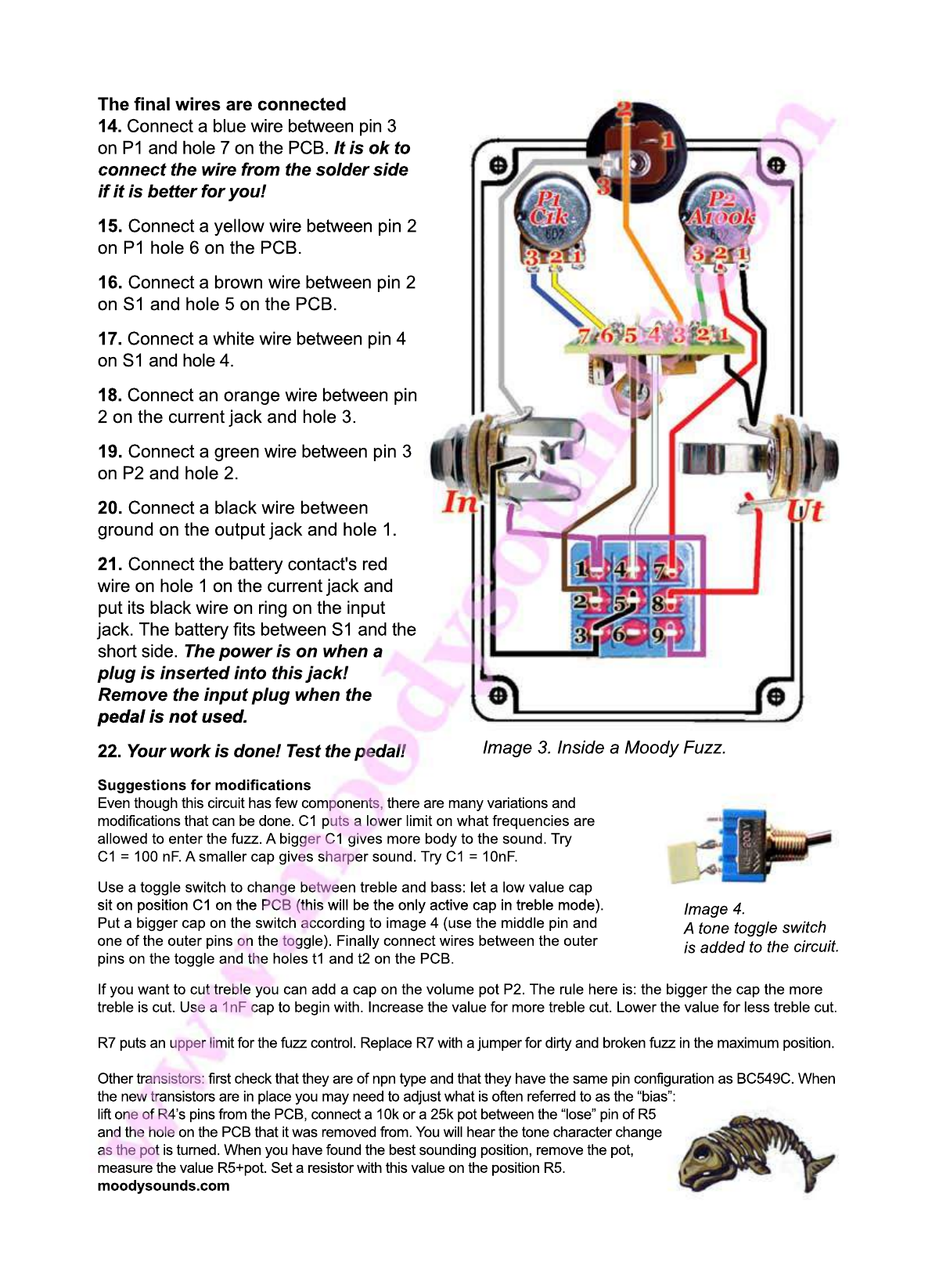
Image 2. S1's pins shall be in parallel
with the short sides of the box.
9. Connect a red wire between pin 2 on P2
and pin 7 on S1.
10. Connect a black wire between pin 1 on P2
and ground on the output jack. Solder the
output jack in step 20!
111. Connect a black wire between ground on
the input jack and pin 3 and pin 5 on S1. Take
off more plastic than normal and put the end
of the wire through both pins.
The PCB is mounted on the LED in the box
12. 12. The LED D1 will hold the PCB in place in
the box. Mount its metal socket and push D1,
together with the insulating plastic piece, into
the socket. Turn D1 so that its longest pin
is to the right, compare with image 2!
13.13. We want the PCB to stand vertical in the
box. Place the tops of D1’s pins in the holes
denoted D1 on the PCB and solder on the
other side. In step 12 we made sure that D1
was turned correctly. Check again that D1’s
longest pin is closest to “the side of the circle
which is not cut off”. The hole, which the
longest pin goes in, is shown with a red arrow
in image 1 and the long pin is red in image 2.
The first wires are connected (those that do not involve the PCB) see image 2
6. Connect a purple wire between tip on the input jack and pin 1 on S1 and, before you solder
pin 1, connect another purple wire between pin 1 and pin 9 on S1.
7. Connect a grey wire between pin 3 on the current jack and ring on the input jack. If you
want to be able to use battery as power supply, solder ring in step 21!
8. Connect a red wire between pin 8 on S1 and tip on the output jack.
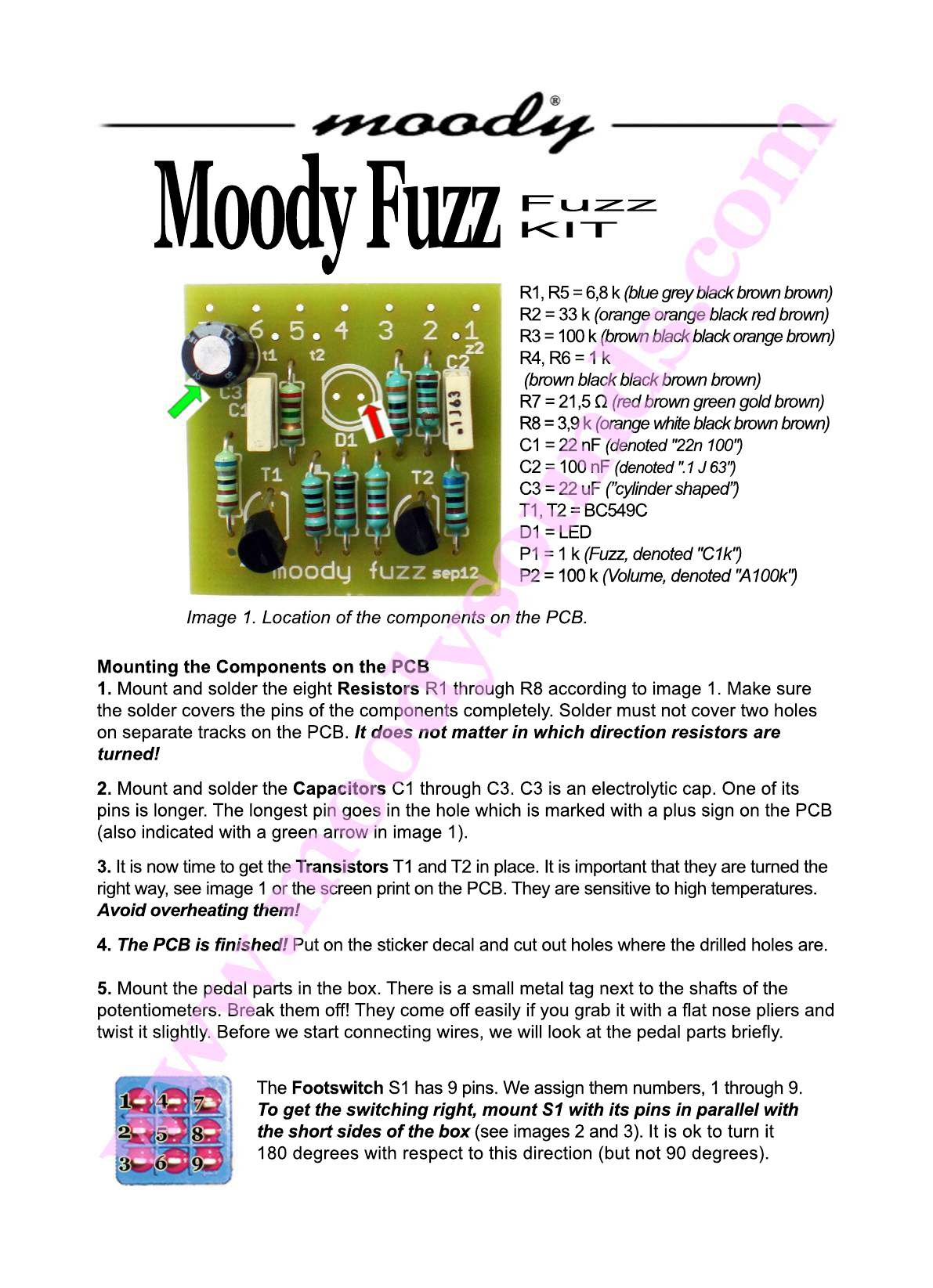
The Current jack has three
solder lugs also. We assign
them numbers 1, 2 and 3,
according to the image.
A Potentiometer has three
solder lugs: 1, 2 and 3. Its
value is written next to its
shaft. P1 and P2 have
different values - do not
confuse them!
The Input jack is stereo. It has
three pins: "tip", "ring" and
“ground". The image shows tip
marked with a red dot and ring
marked with a green dot. Do
not mix them up!
The Output jack is mono. and
it has two solder lugs, which
we call "tip" and "ground". Tip
conducts with the "arm" of the
jack and it is marked with a red
dot in the image to the left.

Suggestions for modifications
Even though this circuit has few components, there are many variations and
modifications that can be done. C1 puts a lower limit on what frequencies are
allowed to enter the fuzz. A bigger C1 gives more body to the sound. Try
C1 = 100 nF. A smaller cap gives sharper sound. Try C1 = 10nF.
Use a toggle switch to change between treble and bass: let a low value cap
sit on position C1 on the PCB (this will be the only active cap in treble mode).
Put a bigger cap on the switch according to image 4 (use the middle pin and
one of the outer pins on the toggle). Finally connect wires between the outer
pins on the toggle and the holes t1 and t2 on the PCB.
If you want to cut treble you can add a cap on the volume pot P2. The rule here is: the bigger the cap the more
treble is cut. Use a 1nF cap to begin with. Increase the value for more treble cut. Lower the value for less treble cut.
R7 puts an upper limit for the fuzz control. Replace R7 with a jumper for dirty and broken fuzz in the maximum position.
Other transistors: first check that they are of npn type and that they have the same pin configuration as BC549C. When
the new transistors are in place you may need to adjust what is often referred to as the “bias”:
lift one of R4’s pins from the PCB, connect a 10k or a 25k pot between the “lose” pin of R5
and the hole on the PCB that it was removed from. You will hear the tone character change
as the pot is turned. When you have found the best sounding position, remove the pot,
measure the value R5+pot. Set a resistor with this value on the position R5.
moodysounds.com
I
m
a
g
e
4
.
A
t
o
n
e
t
o
g
g
l
e
s
w
i
t
c
h
i
s
a
d
d
e
d
t
o
t
h
e
c
i
r
c
u
i
t
.
Image 3. Inside a Moody Fuzz.
The final wires are connected
14. Connect a blue wire between pin 3
on P1 and hole 7 on the PCB. It is ok to
connect the wire from the solder side
if it is better for you!
15.
15. Connect a yellow wire between pin 2
on P1 hole 6 on the PCB.
16. Connect a brown wire between pin 2
on S1 and hole 5 on the PCB.
17. Connect a white wire between pin 4
on S1 and hole 4.
18.
18. Connect an orange wire between pin
2 on the current jack and hole 3.
19. Connect a green wire between pin 3
on P2 and hole 2.
20. Connect a black wire between
ground on the output jack and hole 1.
21.
21. Connect the battery contact's red
wire on hole 1 on the current jack and
put its black wire on ring on the input
jack. The battery fits between S1 and the
short side. The power is on when a
plug is inserted into this jack!
Remove the input plug when the
pedal is not used.pedal is not used.
22. Your work is done! Test the pedal!