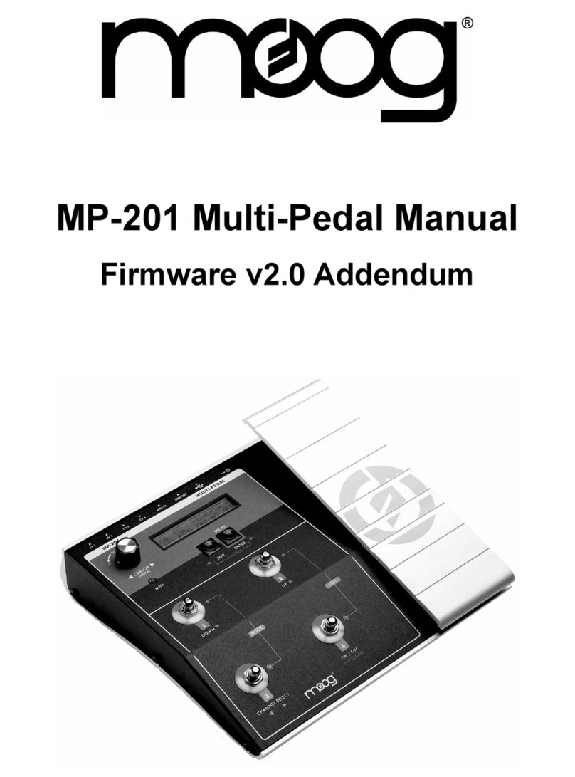
Moog MP-201 Multi-Pedal User manual

Page 3
Table of Contents
Introduction .................................................
Overview and Features ........................
Instant Gratication ................................
Presets Dened ........................................
Controllers and Control Signals ....
Operating Modes ....................................
Chart of Panel Functions ...................
Single Channel Mode ............................
Quad Channel Mode ............................
Edit Mode ....................................................
Edit Mode Menus ....................................
Storing Presets ..........................................
Low Frequency Oscillator Parameters...............
MIDI Implementation ..................................................
Utility Mode ......................................................................
Utility Mode Menus ......................................................
Appendix A - Service & Support Info ...............
Appendix B - Caring for the Multi-Pedal .........
Appendix C - Footpedal Adjustment ................
Appendix D - MIDI Implementation Chart ...
Appendix E - Specications .....................................
Appendix F - Factory Presets .................................
4
5
8
11
12
15
16
17
19
20
21
32
33
37
39
40
48
49
49
50
51
52
MP-201 Multi-Pedal
Userʼs Manual

MP-201 User’s Manual
Page 4
MP-201 User’s Manual
Page 5
Thank you and congratulations on your purchase of the MP-201 Multi-Pedal. The
MP-201 Multi-Pedal is an advanced four-channel CV/MIDI footpedal controller.
The analog CV control outputs consist of four ” jacks located on the back of
the unit. The MIDI I/O consists of both USB and DIN MIDI connectors. The signals
at the outputs are determined by the settings of the four Control Channels, each
programmed in a Preset. Each Control Channel features an analog control output
and can simultaneously transmit MIDI Continuous Controller and Program Change
messages on an assignable MIDI Channel.
The MP-201 Multi-Pedal allows you to perform real-time performance gestures
and musical nuances that would otherwise require the coordinated efforts of
many hands and feet to achieve. It is designed to work with the complete line of
Moogerfooger Analog effects, as well as our Voyager and Little Phatty synthesizers,
and other Control Voltage (CV) and MIDI-compatible devices, or software.
The following pages provide descriptions of the operation, features, and the pro-
grammable options of the MP-201. At the end of this booklet you’ll nd technical
specications, service and warranty information, and contact information if should
you need to reach us.
To get started right away, refer to the Instant Gratication section on page 8.
Introduction
Package Contents
The MP-201 Multi-Pedal is shipped with the following items:
1. The MP-201 Multi-Pedal
2. Power Adapter (12VAC, 500mA output)
3. User’s Manual
4. 2.5mm Allen Wrench (for adjusting the footpedal)
In addition to the MP-201 Multi-Pedal and provided accessories, you will need to
supply:
1. An analog CV or MIDI-capable instrument or device
2. Patch cords and/or MIDI cords
NOTE: Be sure to review and understand the input specications of
any equipment to be controlled by the MP-201 before connecting to
ensure compatibility.

MP-201 User’s Manual
Page 4
MP-201 User’s Manual
Page 5
Overview and Features
The MP-201 Multi-Pedal has 4 analog Control Voltage (CV) outputs and USB/
standard MIDI connectors that can transmit or receive controller information on up
to 4 MIDI channels simultaneously.
Each CV output can be individually programmed as an analog CV with +/- 5V limits,
or a Gate trigger (0V - 5V). The analog CV outputs can be:
- A footpedal-controlled voltage that changes smoothly from a
user-programmed heel value to a user-programmable toe value
- An LFO with user-selected Waveform, Rate, Offset and Amount.
LFO signals can be free running or can be synced to MIDI Clock,
Tap Tempo, or each other. The LFO Footpedal Mode selects the
adjustment of LFO Rate , Amount or Offset with the footpedal
- Random Noise. The LFO Footpedal Mode selects the adjustment
of Noise Amount or Offset with the footpedal.
MIDI controller information can be any combination of up to four MIDI Continuous
Controller (CC) messages (0 – 127) on up to four MIDI channels (one CC per
channel). The MP-201 can also receive MIDI CCs on its assigned MIDI Channels
and output analog CVs based on the CC Values.
A collection of four programmed Channels (CV and MIDI) is a Preset. There are
50 Presets available.
The MP-201 Multi-Pedal offers four modes of operation:
- Single Channel Mode is a performance mode. The footswitches are
used to select programs and channels, turn channels ON/OFF, select
the tap tempo function, and enter tap tempo. The footpedal affects all
Channels that are ON.
- Quad Channel Mode is a performance mode. The footswitches are
used to turn Channels 1–4 ON/OFF, or select the tap tempo function.
The footpedal affects all Channels that are ON.
- Edit Mode provides access to editing menus where you can program
the various parameters that make up a Preset.
- Utilities Mode provides access to non-Preset related functions, such as
SysEx Transfers, Firmware Upgrades, Footpedal Calibrations, etc.

MP-201 User’s Manual
Page 6
MP-201 User’s Manual
Page 7
Here’s a brief look at the MP-201 front and back panel controls and functions:
Front Panel:
1. VALUE encoder/Encoder Pushswitch - The VALUE encoder selects presets
and is used to navigate through editing screens. Rotating the VALUE
encoder changes presets, parameters and values. Pressing the Encoder
Pushswitch moves the cursor.
2. Two-line LCD Display (16 characters/line)
3. EDIT and ENTER/STORE Buttons - for editing and storing Presets. Pressing
both buttons simultaneously displays the Utilities menu, where you can
change global settings and perform functions such as saving presets and
updating the rmware.
4. ‘Gas pedal’ style footpedal controller
5. Four momentary footswitches (FS1-FS4). These switches are used to select
Presets, turn channels ON/OFF, select modes and set the desired tempo
(tap tempo).

MP-201 User’s Manual
Page 6
MP-201 User’s Manual
Page 7
1. Power Switch and Adapter Socket – provides power to the MP-201.
Power is ON when the switch is depressed.
2. USB connector - B-type USB connector that provides USB MIDI functionality
when connected to a Windows XP/Vista or Mac OSX computer with
MIDI-compatible Software
3. MIDI In and Out connectors – for MIDI In and Out connections to
other MIDI devices.
4. Four CV outputs (CV1 - CV4) on standard ” TS jack sockets.
NOTE: The MP-201 requires 12VAC power, 0.5A, which is provided by
the included power supply unit (PSU). Do not attempt to use other PSUs
with this unit - doing so may damage the MP-201.
Back Panel:
6. Four Footswitch LED indicators. The Bi-color LED indicators are used to display
the current ON/OFF state of the four outputs (Red LEDs) and the current
level of the outputs (Amber LEDs).
7. MIDI LED - Indicates MIDI Input activity when lit.
NOTE: The chart on page 16 details the function of the panel controls
in all modes of operation, and is a handy reference for learning how to
navigate through the MP-201’s functions.

MP-201 User’s Manual
Page 8
MP-201 User’s Manual
Page 9
Instant Gratication
Follow these steps to experience some of what the MP-201 Multi-Pedal can do.
Unpack and set up the Multi-Pedal. Connect the supplied AC adapter to the POW-
ER IN jack on the back of the Multi-Pedal, and then make additional connections as
shown. For CV connections, use a standard “ patch cord. For MIDI connections,
use a standard MIDI DIN cable
For Analog CV Control -
1. If you plan to use the Multi-Pedal with a Minimoog Voyager or Little
Phatty setup, plug the other end of the patch cord in the FILTER input
jack. Select a highly resonant patch, and turn the instrument’s FILTER
CUTOFF knob to a low setting.
If you plan to use the Multi-Pedal with a Moogerfooger Pedal, set things
up as you normally would with your instrument, and then plug the
other end of the patch cord into one of the following Moogerfooger
pedal jacks:
MF-101: Plug into the CUTOFF jack, and set the FILTER CUTOFF
knob to a low setting. Set the resonance fairly high.
MF-102: Plug into the FREQ jack. Set the FREQ knob CCW.
MF-103: Plug into the RATE jack. Set the RATE knob CCW.
MF-104: Plug into the TIME jack. Set the TIME knob CCW.
MF-105: Plug into the RATE jack. Set the RATE knob to 12:00.
MF-107: Plug into the FREQ jack. Set the FREQ knob CCW.
2. Adjust your monitoring (amp or headphones) for a comfortable
listening level.

MP-201 User’s Manual
Page 8
MP-201 User’s Manual
Page 9
The Multi-Pedal is now congured as a
standard expression pedal with a Control
Voltage (CV) range of 0 to +5V. If you are
connected to a Voyager or Little Phatty,
playing the keyboard while adjusting the
footpedal will open and close the lter. If
you are connected to a Moogerfooger
pedal, playing your instrument while adjust-
ing the footpedal will change the related
Moogfooger parameter (Cutoff, Rate, Freq,
etc.).
4. On the Multi-Pedal, use the VALUE encoder to select Preset 01
‘REVERSE4’. This time the Multi-Pedal is congured as expression
pedal that works in reverse, where the maximum value is in the heel
position and the minimum value is the toe position.
5. On the Multi-Pedal, use the VALUE encoder to select Preset 02
‘TRIANGLE’. The Multi-Pedal is now congured to output a Low
Frequency Oscillator (LFO) Triangle wave CV where the footpedal
is congured to control the speed (RATE) of the LFO.
6. Presets 03 thru 08 offer variations of LFOs (square, sawtooth,
sample & hold, etc.). Feel free to experiment with all of them, and
then try some different patch routings with the Moogerfoogers or
Voyager/Little Phatty.
3. On the Multi-Pedal, use the VALUE encoder to select Preset 00
‘EXPRESSR’. The Multi-Pedal LCD should appear as shown below.
For MIDI Control -
If you are a MIDI musician, try the following example:
1. Plug the other end of the MIDI cord from the MP-201 to the MIDI IN
jack of your MIDI Instrument or MIDI Device.

MP-201 User’s Manual
Page 10
MP-201 User’s Manual
Page 11
These simple examples only serve to familiarize you with the MP-201 Multi-Pedal in
a very basic way. When you realize that the MP-201’s four Channels, each consist-
ing of an Analog CV and MIDI CC, can be individually congured and controlled
simultaneously, you can begin to appreciate the many creative control possibilities
the MP-201 Multi-Pedal can provide.
2. On the Multi-Pedal, use the VALUE encoder to select Preset 33,
‘MIDI CCs’. The Multi-Pedal LCD should appear as shown below.
The Multi-Pedal is now congured as an
expression pedal that is setup to transmit
MIDI CC messages for Mod Wheel (CC#1),
Breath (CC#2), Volume (CC#7) and Foot-
Ctl (CC#4) on MIDI Channel 1. If your
MIDI device is setup to receive MIDI CC’s
on MIDI channel 1, moving the footpedal will
have the same effect as moving the Modula-
tion Wheel on a MIDI keyboard controller.
Consult the documentation that came with
your MIDI Instrument or MIDI Device for
additional conguration information.
NOTE: Adventurous users are encouraged to grab a few more patch
cords and check out the Factory Presets that appear in Appendix F. The
Factory Presets include specic setups for the Voyager and Little Phatty
synthesizers, as well as setups for Moogerfooger pedals (MF101 thru
MF107), MIDI setups, and more.
Connecting your MP-201 to computer via USB
The MP-201 can perform MIDI In/Out functions over a USB cable on either a
Windows XP/Vista computer or a Macintosh OSX computer. The MP-201 uses
standard drivers, so it does not require you to install any special software prior to use.
Before you start the MIDI application you wish to control with your MP-201, simply
connect the MP-201 to the computer with a USB cable. If you are using a Windows-
based PC, the computer will acknowledge that it has recognized the MP-201 as a
USB Composite Device and as a USB Audio Device, and will inform you when the
hardware is installed and ready to use (for Mac users, the Multi-Pedal is ready to be
used as soon as it is plugged in). Once the Multi-Pedal is connected via USB, you may
start your MIDI application and select the MP-201 Multi-Pedal as a MIDI Input or
Output device for that program. Be sure not to echo the application’s MIDI In to its
MIDI Out, as a MIDI loop is then formed, and unpredictable results can follow.

MP-201 User’s Manual
Page 10
MP-201 User’s Manual
Page 11
Presets Dened
A Preset is a collection of four programmed Control Channels (see gure below).
Each channel can be programmed to specify a Control Voltage (CV), a MIDI
Continuous Controller message, or both. There are a total of 50 presets available
(Preset #00-49).
Presets can be named (8 characters max.), and each Channel in a Preset can have
it’s own name (8 characters max). The Channels in a Preset can be individually
switched ON or OFF, and be programmed for any one of three Channel Modes:
Expression (expression pedal operation), Gate (ON/OFF trigger operation) or LFO
(modulation control).
Presets are selected by using the VALUE encoder, by Footswitches, or remotely by
MIDI Program Change messages (when connected to a MIDI device). If Presets are
selected manually, when the highest Preset value is reached (Preset #49), advancing
the value once more wraps back to Preset #00.
When a Preset is selected, the initial values, initial ON/OFF state and MIDI program
change messages that are assigned in the Preset are output.

MP-201 User’s Manual
Page 12
MP-201 User’s Manual
Page 13
A controller is a device that does not make any sound on its own, but is used to
control another sound producing device (like a synthesizer), or a sound altering
device (such as an effects module). Some devices respond to analog control signals,
called Control Voltages (CVs) and Gates, and some devices respond to digital control
messages through MIDI (Musical Instrument Digital Interface) commands. Some
devices, such as the Moog Little Phatty®, respond to both.
When we talk about controlling a sound-producing device, it can be as simple as
adjusting the volume of the device with a knob. In this case think of the control as the
signal produced by the knob that tells the device’s electronic ‘innards’ what the volume
should be – as the control signal goes lower (by turning the knob down) the volume
goes lower. As the control signal goes higher (by turning the knob up) the volume
goes higher. This is an imaginary example, but it illustrates how, with a control signal,
you can alter the sound (in this case the volume) of a sound-producing device.
Analog Control Signals: CVs and Gates.
CV stands for Control Voltage. Voltage is the measurement of electrical potential; the
unit is Volts (V). When a circuit is Voltage-Controlled, it has inputs that receive a CV
and turn it into a setting for a parameter such as pitch or volume. The Voltages and
Currents used for most CV gear are relatively small and not dangerous, but there is
not a standard for what voltage levels are used. The MP-201 outputs 0V to +5V in
Unipolar Mode (the default), and -5V to +5V in Bipolar Mode (see the CV SCALE
menu, page 40). It is up to the MP-201 user to know and understand the input
requirements of their analog gear before connecting the MP-201. Some analog gear
may not be able to accept negative voltages! All current Moog gear is compatible with
the CV outputs of the MP-201, including all Moogerfooger® Analog Effects, Minimoog
Voyager® Synthesizer and the Little Phatty® Synthesizer.
A CV can be produced by rotating a rotary control, or in the case of the MP-201
when used as in Expression Mode, by changing the position of the footpedal. This type
of CV can be used for smooth, precise and expressive changes.
A CV can also be produced automatically by a function known as a Low Frequency
Oscillator (LFO). An oscillator is a circuit that goes up and down at a regular time
interval with a repeating shape, known as a Waveform. The RATE at which the LFO
goes up and down is the frequency. The LFO is low frequency because it produces
vibrations lower than the human ear can hear. We can hear vibrations as low in
frequency as 20 times per second or 20 Hertz (Hz). The MP-201 can produce LFO
signals from .1 Hz to 1000 Hz. At lower rates, effects can include tremolo, vibrato,
Controllers and Control Signals

MP-201 User’s Manual
Page 12
MP-201 User’s Manual
Page 13
trills, or slow rhythmic sweeps, while oscillations in the audio range can be used
to create truly wild sonic effects, including frequency modulation (FM), amplitude
modulation (AM), and timbre modulation.
A CV can also be a randomly generated signal. If it is continuously random, it is called
Noise, similar to the static white noise that can be picked up on an analog radio
tuned between stations. If it is a random voltage that changes only at regular periodic
intervals, then we refer to this type of voltage as Sample and Hold, or S+H.
The MP-201 offers a number of LFO waveforms as shown in the gure below. Each
graph shows the way the voltage varies with time.
The height of the LFO waveform shows its amplitude. In the MP-201, this parameter
is called the ‘LFO AMOUNT’
The center of the LFO waveform (along the horizontal axis) can be shifted up or
down by means of an offset voltage. This means that you can have a LFO centered
around 0V, or shifted up and centered around +2.5V, for example. In the MP-201, this
parameter is called the ‘LFO OFFSET.’
Finally, a Gate is a type of analog control signal that is either low or high, and changes
abruptly, not smoothly. A Gate is used to trigger events, or to turn circuits ON or OFF.
The MP-201 outputs a Gate that is 0V = OFF and +5V = ON.
Triangle waveform Square waveform Ramp waveform
Sawtooth waveform Sample & Hold
waveform
Noise
Gate: OFF ON OFF

MP-201 User’s Manual
Page 14
MP-201 User’s Manual
Page 15
MIDI
MIDI was developed as a standard way of communicating control signals digitally for
musical devices or software across a MIDI or USB cable. Standard MIDI cables use 5-pin
DIN connectors, and each cable can send MIDI data (MIDI OUT) or receive MIDI Data
(MIDI IN). USB Cables combine both MIDI In and MIDI Out functions. MIDI data is
sent as Messages. There are two categories of messages: Channel messages and System
Messages.
MIDI allows for up to 16 MIDI Channels on each MIDI Cable – thus Channel messages
are assigned to one of sixteen MIDI Channels. The different channels can be used to
address different devices, or different sounds or sound parameters within a single device.
Types of Channel Messages include Note On/Note Off (not used in the MP-201),
Program Change Messages (used to select presets in a device) or Continuous Controller
(CC) Messages. CC Messages are like the CVs of MIDI – they are a control signal with
128 levels. In many MIDI devices, CCs can be used in a manner akin to a CV, changing
pitch or volume for example.
A System Message is a general message and does not address a particular channel. A
System Exclusive (SysEx) message is a type of System message that is dened only for
a particular device, so that other devices will ignore it. That could be the settings of a
particular preset, or the collected settings of a bank of presets, or it could be a larger le
such as a rmware le that updates the operating system of the device. A MIDI CLOCK
message is a type of System Message that is a REAL TIME message and provides tempo
information to other MIDI devices. There are 24 MIDI Clock messages transmitted for
every quarter note. The MP-201 can be set to sync LFOs to various time divisions of a
current tempo by MIDI clock messages.
Please note that though MIDI is a standard communications protocol, it is old (published
in 1983), serial (sends one message after the other), and slow (31.25 Kbaud). The MP-
201 can send out a lot of MIDI data at once, especially when a Preset Channel is set as
an LFO. Some devices and software may not handle this data in a predictable way. It
is up to the user to know and understand the MIDI implementation of a device before
connecting it to the MP-201. Also be aware that MIDI loops (connecting MIDI In to
MIDI Out on two devices) may occur when using the MP-201 with sequencer software.
This should be avoided, especially when using the MIDI USB connection, as MIDI loops
can cause unpredictable behavior.

MP-201 User’s Manual
Page 14
MP-201 User’s Manual
Page 15
Operating Modes
The controls on the Multi-Pedal perform multiple functions as indicated on the front
panel of the unit. In order to organize these functions into logical groups, the Multi-
Pedal uses the concept of ‘Operating Modes’. There are four Operating Modes:
- Single Channel (SGL) Mode
- Quad Channel (QD) Mode
- Edit Mode
- Utilities Mode
The Single Channel and Quad Channel modes are the Performance Modes, where
the Multi-Pedal footpedal and footswitches is employed as a performance controller.
The Edit and Utility Modes are the Programming Modes, where you specify Preset
parameters and perform global and System Exclusive operations.
The gure below shows the relationship of the four Operating Modes. Navigation
between modes is performed via the panel buttons and footswitches. Pressing FS1
and FS3 together toggles between Performance Modes (SGL, QD). Pressing the
EDIT button, or FS2 and FS4 together, places you in Edit Mode. Pressing the EDIT
and ENTER buttons simultaneously places you in Utilities Mode. The Edit and Utilities
Modes are accessible from any other mode as shown. Note that once you are in Edit
or Utilities Mode, you will be returned to the previous operating mode when you exit.
For example, if you entered Edit Mode from SGL Mode, you will return to SGL Mode
when you exit.
Detailed descriptions of the four Operating Modes follows. A table showing the
Multi-Pedal panel control functions for the various Operating Modes appears on the
next page.
Multi-Pedal Operating Modes

MP-201 User’s Manual
Page 16
MP-201 User’s Manual
Page 17
Multi-Pedal Panel Controls

MP-201 User’s Manual
Page 16
MP-201 User’s Manual
Page 17
Single Channel Mode
Single Channel Mode is the default operation mode when the Multi-Pedal is rst
powered up. Single Channel Mode (SGL) allows you to:
- view and edit the current Preset name,
- view information about the current Channel
- select the current Preset with footswitches.
In SGL Mode, the movement of the footpedal will affect any of the channels that are
ON in the manner dened by the Channel Mode and settings of the Channels in
the preset. The bottom two footswitches (FS3 & FS4) select and turn ON/OFF the
individual Channels, while the top two footswitches (FS1 & FS2) select the Presets.
LCD Display
In SGL Mode , the top line of the LCD displays the Preset Name and Number, while
the bottom line displays the current Channel information. The bottom right corner
of the display defaults to displaying the Channel name, but can also be set to display a
precision value, an MIDI CC value, or the output voltage (see the Display Units menu
on page 42 for more information).
Footswitch Indicators
The Footswitch Bi-color LED indicators 1-4 correspond to the current Preset’s
channel outputs. They show which channels are ON or OFF using a Red LED and the
current output level using variable brightness Amber LEDs.

MP-201 User’s Manual
Page 18
MP-201 User’s Manual
Page 19
Preset Names
Preset Naming is only available in Single Channel Mode.
To name a Preset, press the Encoder pushswitch.
The cursor will move to the rst letter in the Preset
name eld. Use the VALUE encoder to selected the
desired character.
Press the ENTER button to move the cursor to the
next character. Use the VALUE encoder again to
select the desired second character, and so forth, until
all characters are chosen. When Preset naming is
completed, press the Encoder pushswitch to return
the cursor to the Preset Number eld.
NOTE: While the cursor is in the Preset Name eld, the ENTER/STORE
button moves the cursor to the right, while the EDIT button moves the
cursor to the left. The cursor will wrap when the left-most or right-most
character is reached.

MP-201 User’s Manual
Page 18
MP-201 User’s Manual
Page 19
Quad Channel Mode
Quad Channel Mode (QD) provides access to controlling all four channels at the
same time. Each footswitch controls the ON/OFF state of the channel indicated by
the Channel number. The movement of the footpedal will affect any of the Channels
that are ON in the manner dened by the Channel Mode and settings of the Channels
in the preset.
Quad Channel Mode provides:
- instant access to turning any of the four channels ON/OFF.
- viewing the status of all four Channels at once
- fast access to the Tap Tempo functions on all four channels (if applicable).
LCD Display
In Quad Channel Mode, the top line of the LCD displays “QD”: the current
Operating Mode, and the status of Channels 1& 2, while the bottom line displays
the current preset number and the status of Channels 3 & 4 as shown below. In the
factory default conguration (DISPLAY UNITS = OFF), the LCD displays the Channel
Modes (Expression, Gate or LFO), but this can be programmed to show the actual
CV values instead .
Footswitch Indicators
The Footswitch Bi-color LED indicators 1-4 correspond to the current preset’s
channel outputs. They show which channels are ON or OFF using a Red LED and the
current output level using variable brightness Amber LEDs

MP-201 User’s Manual
Page 20
MP-201 User’s Manual
Page 21
Edit Mode
Edit Mode allows you to edit the parameters of a Preset. Edit Mode can be entered
from Single Channel Mode or Quad Channel Mode simply by pressing EDIT or by
pressing FS2 & FS4 simultaneously.
In Edit Mode, the VALUE Encoder or footswitches 1 & 2 (FS1 and FS2) are used to
scroll through the edit menus. In any menu, pressing the Encoder pushswitch or FS4
moves the cursor to the bottom line of the LCD, where you can change the edit value
using the VALUE Encoder. Pressing the Encoder pushswitch or FS4 again moves the
cursor back to the top line of the LCD.
NOTE: When the cursor appears in the value eld, the footpedal
is used to set Footpedal Parameter values, such as the Heel,
Toe and Initial values. The VALUE encoder can be used for ‘ne’
adjustments to these values.
Footswitch 3 (FS3) is used to select the Channel or Preset MIDI routing for editing
(CH1, CH2, CH3, CH4, or ALL). You can change the current Channel (or MIDI ALL)
at any time while in Edit Mode.
To exit from Edit Mode at any time, press the EDIT button again. Note that any
changes made to Preset parameters are maintained until the Preset number is
changed, but will be lost if you do not save them (see ‘Storing Presets’, page 32).
NOTE: When you edit the ‘Heel’, ‘Toe’, an ‘Initial’ values in Expres-
sion Mode and LFO Mode, and the ‘Rate’, ‘Amount’ and ‘Offset’
values in LFO Mode, the footpedal has no effect on any other
Channel, or any other parameter. The CV and MIDI outputs reect
the voltage/MIDI CC values of the footpedal position, allowing you to
‘hear’ what the actual values are.

MP-201 User’s Manual
Page 20
MP-201 User’s Manual
Page 21
Edit Mode Menus
The menu trees shown on the following pages will assist you in navigating through the
available Preset editing parameters. Note that the menus are dynamic, which means
that the available parameters change based on the selected Channel Mode.
The menu trees show the parameters, values and descriptions for each menu item.
Control Voltage values are displayed as a range from 0 – 4095 (‘PRECISION’ units
- the factory default view), which represents the total programmable voltage range.
If you’d rather work in volts, you can change the view from ‘PRECISION’ to ‘VOLTS’
using the ‘DISPLAY UNITS’ Utilities menu (page 42).
All control voltages have a total programmable range of +/-5V (bipolar). As shipped
from the factory, however, the Multi-Pedal is congured for a unipolar range of 0-5V.
If you wish to work with bipolar voltages, go to the ‘CV SCALE’ Utilities menu (page
40) and select ‘BIPOLAR’.
NOTE: The choice of CV Scale (Unipolar or Bipolar) affects all
CV parameters globally.
PRECISION values have a total range of 0 - 4095 regardless of whether the CV
voltage range is Unipolar or Bipolar. This means that a precision value of ‘0’ can
indicate either 0 Volts (in Unipolar mode), or -5V (in Bipolar mode). The tables below
show the how to interpret the values:
UNIPOLAR
Value = Volts Value = Precision
0 0
+1.25 1024
+2.50 2048
+3.75 3072
+5.00 4095
BIPOLAR
Value = Volts Value = Precision
-5.00 0
-2.50 1024
0 2048
+2.50 3072
+5.00 4095

MP-201 User’s Manual
Page 22
MP-201 User’s Manual
Page 23
>
>
VALUES:
Available character set (numbers, upper
case, lower case), 8 characters max.
ON, OFF
EXPRESSION, GATE, LFO
OFF, 1 – 16
Default: 1
0 – 127
Default: 1
LSB 0 – 128, MSB 0 – 128
Default:
OFF, 0 – 128
Default:
PARAMETERS:
EDIT Mode menus - Common Parameters
:
:
:
Other manuals for MP-201 Multi-Pedal
2
Table of contents
Other Moog Music Pedal manuals
Moog
Moog MP-201 Multi-Pedal User manual
Moog
Moog MF Drive User manual
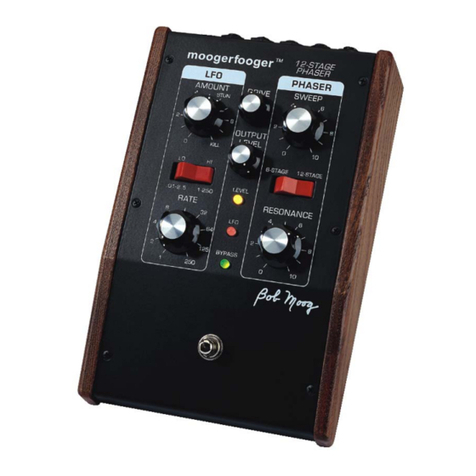
Moog
Moog moogerfooger MF-103 User manual
Moog
Moog MF-108M Cluster Flux User manual
Moog
Moog EP-2M User manual

Moog
Moog MP-201 Multi-Pedal User manual

Moog
Moog moogerfooger MF-103 Manual
Moog
Moog Taurus 3 User manual
Moog
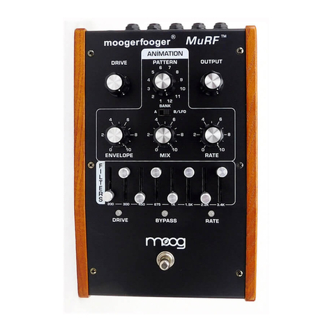
Moog Moogerfooger MF-105B Bass MuRF User manual
Moog
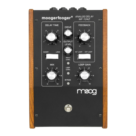
Moog moogerfooger MF-104Z Quick start guide
