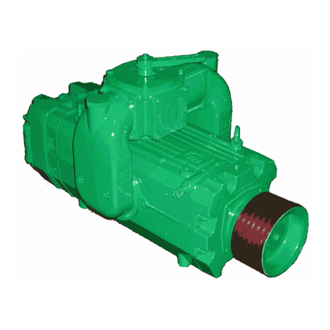
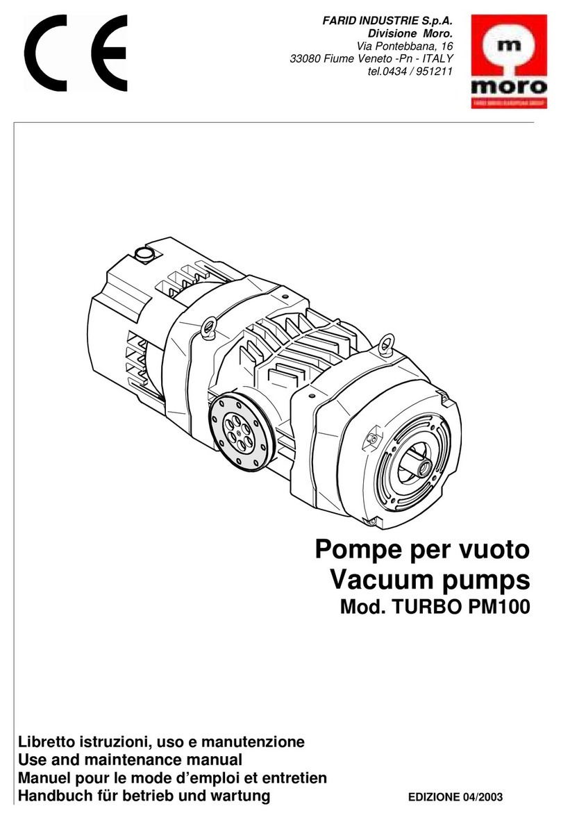
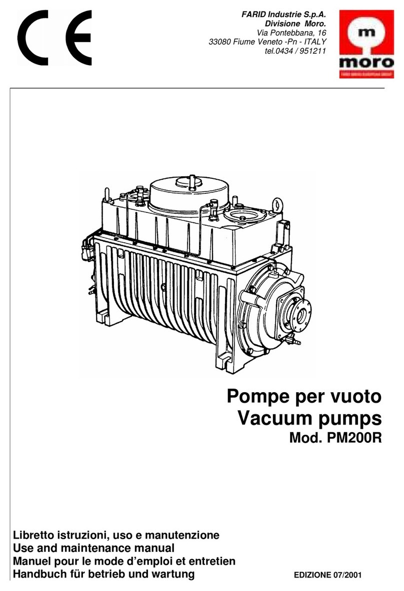
Moro Air Series User manual

Rev. 00 of 1 September 2008 1 / 29
Series
PM 60-70-80A
USE AND MAINTENANCE MANUAL
Email: sales@morousa.com
www.morousa.com
PITTSBURGH, PA OFFICE
Sales Office
(800) 383-6304
(412) 415-0421
Fax: (412) 415-3154
ST. LOUIS, MO OFFICE
Po Box 632
Union, MO 63084
(866) 383-6304
Fax: (636) 583-2044
MORO USA, INC.

Rev. 00 of 01.01.2009 2 / 29
PREMISE
The vacuum pumps Farid - MORO S.p.A. division - are designed and manufactured in
compliance with EC safety standards and subject to risk evaluation according to standard EN
1050; in particular they comply with directive 98/37/CE and later amendments and integrations.
This manual includes the Declaration of the Manufacturer as per the above directive and all the
indications necessary to the users and manufacturers of equipment to use our products in
safety; thus the manual must always be kept near the vacuum pumps. It is necessary to read
carefully the instructions included in this manual before proceeding with any operation with or
on the vacuum pumps.
This symbol of danger in the manual means that important safety instructions are
given. These are directed to the operator, who is responsible for their respect by
him and as well by other people exposed to the risks related to the use of the
equipment.
The descriptions and illustrations in this manual are solely indicative. The Manufacturer
reserves the right to perform any type of change, at any time.
WARRANTY
When receiving the equipment, verify that all the parts of the vacuum pump are included.
Any anomaly or missing part must be notified within 8 days from receipt. The Supplier
guarantees that the goods sold are exempt from faults and defects and undertakes, only
when such faults are clearly due to the manufacturing process or to the materials used,
to repair or, based on its final assessment, to replace the defective parts. The Buyer
shall be fully charged for labour, travel, transport, and duty expenses (if any). The Seller
is not liable for damage compensation except in case of malice or negligence. The parts
normally subject to wear are not covered by the warranty.
Warranty is void in the following cases:
The defects are due to accidents or evident negligence of the Buyer.
The parts have been modified, repaired or fitted by people not authorized by the
Seller.
Failures and breakages have been caused by unsuitable uses or stresses exceeding
those indicated in the maintenance booklet provided by the seller.
The buyer has not complied with contractual payment obligations. The right to the
warranty of the Buyer is void if the defects are not noticed to the Seller within 8 days
form their discovery, in derogation to the clause 1512 of the Civil Code. The Seller
reserves the right to change or improve its products without being obliged to
change or improve the previously manufactured and/or delivered units. The Seller is
not responsible for incidents or effects of the accidents on persons or goods due to
defects of materials and/or manufacturing.

Rev. 00 of 01.01.2009 3 / 29
MANDATORY SAFETY SIGNS THAT MUST BE POSITIONED ON
THE WORKPLACE AND AROUND THE VACUUM PUMP
Moving parts
High temperature alert
Crushing
Mandatory personal safety
devices
Do not touch the drive shaft or any other moving parts when in use.
Periodically lubricate the power takeoff.
Read this manual before starting to use the vacuum pump
Before start up verify the direction of the rotation of the switch lever to select vacuum (air flows
away from the tank) or pressure (air flows towards the tank).

Rev. 00 of 01.01.2009 4 / 29
USE CONDITIONS AND LIMITS - LIST OF DANGERS
Installation must comply, for EC countries, with directive 98/37/CE and later
amendments, while for the other countries it must comply with local safety standards.
This vacuum pump is designed to create a vacuum or a pressure inside the connected
tank. No liquid, dust and solid material must enter the vacuum pump because this may
damage it. It is necessary therefore to provide the equipment with safety overfill valves.
Any use of the vacuum pump different from that described in this manual, is to be
considered as strictly forbidden, not foreseen by the Manufacturer and thus highly
dangerous.
Do not use the vacuum pump for flammable materials, explosives or materials that
release flammable gas.
Do not use the vacuum pump in potentially explosive atmospheres.
Never remove the guards provided on the vacuum pump and check for their
efficiency each time the machine is used.
Any maintenance work must be performed with machine stopped.
Non-compliance with the indications of this manual can result in the following dangers:
Danger of crushing due to the weight of the vacuum pump during handling and
transport.
Danger of entanglement in the moving parts in case of removal of the guards.
Thermal dangers due to high temperature reached by the vacuum pump.
Acoustic danger due to the noise generated and to lack of use of personal hearing
protection devices.
Shearing danger for the operator during test with suction and/or discharge hoses
detached from the pump.
Danger of projection of solid and liquid materials due to severe breakage of the
vacuum pump.

Rev. 00 of 01.01.2009 5 / 29
TABLE OF CONTENTS
PREMISE 2
WARRANTY 2
MANDATORY SAFETY SIGNS 3
USE CONDITIONS AND LIMITS - LIST OF DANGERS 4
TABLE OF CONTENTS 5
GENERAL INFORMATION 7
1 -VERSIONS OF THE VACUUM PUMP 7
USE AND MAINTENANCE INSTRUCTIONS 8
2 -PACKAGING, STORAGE, HANDLING AND TRANSPORT 8
2.1 PACKAGING 8
2.2 STORAGE 8
2.3 HANDLING AND TRANSPORT 8
3 -ASSEMBLY, INSTALLATION, DISASSEMBLY, REASSEMBLY 8
3.1 INSTALLATION LAYOUT 9
3.2 ASSEMBLY AND FITTING - INSTALLATION 9
3.3 REMOVAL 10
3.4 DISASSEMBLY 10
3.4.1 REAR SECTION DISASSEMBLY 10
3.4.2 FRONT SECTION DISASSEMBLY 11
3.5 REASSEMBLY - REINSTALLATION 11
3.5.1 REASSEMBLY OF THE REAR SECTION 11
3.5.2 REASSEMBLY OF THE FRONT SECTION 11
3.6 CORRECT POSITIONING OF THE DIVERTER VALVE 12
4 -HYDRAULIC LAYOUT (VERSION AH) 13
4.1 HYDRAULIC MOTOR USE AND MAINTENANCE INSTRUCTIONS 13
5 -COMMISSIONING - ADJUSTMENTS 14
5.1 OPERATION WITHOUT OVERPRESSURE/VACUUM VALVE FOR SERIES AIR 14
5.2 DIRECTION OF ROTATION 14
6 -OIL LUBRICATION AND CONTROL SYSTEM 14
6.1 FORCED LUBRICATION WITH GEARS 14
6.2 AUTOMATIC LUBRICATION 14
6.3 OILTO BE USED 15
6.4 OIL LEVEL 15
6.5 AMOUNT OF LUBRICATION OIL 15
6.6 LUBRICATION OIL REGULATION 16

Rev. 00 of 01.01.2009 6 / 29
7 –PRESSURE AND VACUUM RELIEF VALVES 16
8 -TEST AND RUN-IN 18
8.1 TEST 18
8.2 RUN-IN 18
9 -START-UP, OPERATION, STOP 19
9.1 START-UP 19
9.2 OPERATION 19
9.3 STOP 19
9.4 CONTROL DEVICES 19
9.5 PROTECTION DEVICES USED 20
9.6 PERSONAL PROTECTION DEVICES TO BE USED 20
10 -TROUBLESHOOTING 21
11 -MAINTENANCE, TESTS, REPAIRS, TECHNICAL SERVICE 22
11.1 CLEANING 22
11.1.1 WASHING OF BODY 22
11.1.2 WASHING OF OIL TANK 22
11.1.3 WASHING AND CLEANING OF VALVES 22
11.2 VALVES CHECK 22
11.3 INSPECTION AND REPLACEMENT OF THE VANES 22
11.3.1 FEATURES OF THE VANES 22
11.3.2 INSPECTION OF THE VANES 23
11.3.3 REPLACEMENT OF THE VANES 24
11.3.4 DIMENSIONS OF VANES (NEW) 24
11.4 REPLACEMENT OF THE RUBBER CHECK BALL 24
11.5 REPLACEMENT OF THE GEARS 24
11.6 TECHNICAL SERVICE 24
11.7 PERIODIC MAINTENANCE 24
12 -DECOMMISSIONING AND DEMOLITION 25
COMPANY CERTIFICATION IN COMPLIANCE WITH THE REQUIREMENTS OF THE STANDARD UNI EN
ISO 9001:2000 26
DECLARATION OF THE MANUFACTURER 27

Rev. 00 of 01.01.2009 7 / 29
GENERAL INFORMATION
1. VERSIONS OF THE VACUUM PUMP
The vacuum pumps of the AIR series can be delivered in the following versions:
AIR SERIES
AM
AP
AD
AH
P M 6 0 A
O
O
O
O
P M 7 0 A
O
O
O
O
P M 8 0 A
O
O
O
O
Table 1 O = Available
TECHNICAL SPECIFICATIONS
Description
Ref.
PM 60A
PM 70A
PM 80A
Free flow rate
c.f.m.
252
322
417
Max. power required
hp
15.6
17.8
20.2
Max. vacuum
bar
95%
95%
95%
Max. absolute pressure
p.s.i.
29
29
29
Weight
lbs
265
309
357
AM VERSION with overgear
The pump shaft is a 1 3/8” spline and run at 540 rpm. This version can be recognized by
the overgear box and by the identification plate located on the vacuum pump.
AP VERSION with pulley application
The pump is driven by a drive pulley (not provided) and an idle pulley (provided on request)
and run at 1000 rpm. This version can be recognized by the identification plate located on
the vacuum pump.
AD VERSION with direct drive
The pump shaft is 1 3/8” keyed and run at 1000 rpm. The version can be recognized by the
identification plate located on the vacuum pump.
AH VERSION with hydraulic drive
The pump is driven by a hydraulic motor (provided on request) and it is recognizable by the
support for hydraulic motor and by the identification plate located on the vacuum pump.

Rev. 00 of 01.01.2009 8 / 29
USE AND MAINTENANCE INSTRUCTIONS
2. PACKAGING, STORAGE, HANDLING AND TRANSPORT
2.1 PACKAGING
The AIR series vacuum pumps are provided without packaging. Packaging, such as wooden
crates, can be requested for air or sea transport.
2.2 STORAGE
For correct storage, the vacuum pump must be stored:
indoor, protected from weather conditions;
in horizontal position, resting on 4 feet.
The vacuum pumps are lubricated, during test, at our plant, with a specific oil which
ensures lubrication of inner components for approx. 6 months. In case of storage, we
recommend to clean the inside of the pump with diesel fuel (or kerosene) and oil (as
indicated in this manual).
2.3 HANDLING AND TRANSPORT
Weight of the vacuum pump: (see annexed Technical Specifications).
The vacuum pump must be:
1. Slung by metal hooks to be inserted into the eyebolt, or sling.
2. Lifted by forklift (if on pallet), bridge crane, crane.
The vacuum pump is provided, as standard, with protection compliant with EC directives, which
must be fitted by the installer using the screws provided.
3. ASSEMBLY, INSTALLATION, DISASSEMBLY, REASSEMBLY
During maintenance, inspection, use and repair, we recommend the use of
personal protection devices listed at the beginning of the manual.

Rev. 00 of 01.01.2009 9 / 29
3.1 INSTALLATION LAYOUT
Vacuum pump assembly layout (figure 1)
Maintenance, inspection, use and repair must be performed with maximum care,
with the drive switched off and the power take off disengaged.
It is absolutely mandatory to avoid the ingestion of foreign bodies in the vacuum
pump as this is likely to cause damage to the pump.
It is thus necessary to provide the system with a primary trap “1” and a secondary
trap “2” between the vacuum pump and the tank
(see Figure 1).
3.2 ASSEMBLY AND FITTING - INSTALLATION
The vacuum pump must be assembled and installed following this procedure:
1. Assemble the vacuum pump in horizontal position with its feet facing downward. The
position of assembly on the vehicle must be easily accessible and protected. It is
necessary not to exceed a longitudinal angle of 5° on the horizontal plane.
2. Position the vacuum pump and fasten it by means of bolts, nuts and washers in the
specific slots or holes provided in the feet.
3. To install the vacuum pump:
- version with overgear (…AM) it is necessary to connect the coupling of the 540

Rev. 00 of 01.01.2009 10 / 29
rpm PTO to the spline shaft of the vacuum pump.
Do not exceed the maximum allowed angle of the PTO coupling
- version with pulley (…AP) it is necessary to insert an idle pulley sheave on the
drive shaft of the vacuum pump and fasten it by means of specific screw located in
the front area of the shaft. The idle pulley can be directly mounted on the keyed
shaft. Mount this sheave as near as possible to the bearing. Never transmit axial
loads. Connect the two pulleys - the idle pulley to the drive pulley - by means of
drive belts of suitable length. The number and type of belts used should be
specified by the sheave manufacturer. At the end of this operation, it is necessary
to install a belt guard (covering all belts and pulley sheaves) required to protect all
operators.
- - version with direct drive (…AD) it is necessary to connect the shaft of the PTO,
gas/diesel drive or 1000 rpm electric motor to the drive shaft of the vacuum
pump.
Do not exceed the maximum allowed angle of the drive shaft.
-hydraulic version (…AH) it is necessary to fit a hydraulic motor (SAE B 4 bolt for
AIR series) and Moro hydraulic drive bracket and coupling to the pump.
4. Connect the rubber suction and discharge hoses from the tank to the vacuum pump
fastening it to the hose barb fittings provided by means of a properly sized metal clamp.
3.3 REMOVAL
The vacuum pump must be removed following this procedure:
1) stop the power takeoff.
2) remove the connections to the power takeoff and remove hydraulic connection (if any).
3) remove the hosing that connects the vacuum pump to the tank.
4) remove the mounting screws and remove the vacuum pump.
3.4 DISASSEMBLY
3.4.1 Disassembly of the driven side section
Remove the driven side cover with the lubrication pump (together with the coupling)
from the endplate.
Remove the screws from the driven side endplate.

Rev. 00 of 01.01.2009 11 / 29
Use two screws to be turned clockwise into the extraction threaded holes until the
endplate can be removed.
3.4.2 Disassembly of the drive side section
Overgear (…AM)
Pulley (…AP)
Direct (…AD)
Hydraulic (…AH)
1) Remove the gearbox
cover screws.
2) Use two screws to be
turned clockwise in the
extraction threaded holes
until the cover can be
removed.
3) Remove the gear with
taper shaft using a puller if
required.
4) Pinion: first unscrew
the self-locking nut, then
use a puller or press.
5) Remove the gearbox
unscrewing the screws.
6) Remove the rotor from
the body.
1) Remove the idle pulley
and the key.
2) Remove the front cover
from the endplate.
3) Remove the screws
from the drive side
endplate.
4) Remove the rotor from
the body.
1) Remove the coupling
with transmission flange
and the key.
2) Remove the drive side
cover from the endplate.
3) Remove the screws
from the drive side
endplate.
7) Remove the rotor from
the body.
1) Remove the hydraulic
motor from the support.
2) Remove the hydraulic
motor support.
3) Remove the fastening
screw inside the coupling
and then remove it.
4) Remove the screws from
the drive side endplate.
5) Remove the rotor from
the body.
3.5 REASSEMBLY - REINSTALLATION
IMPORTANT: Before any reassembly, replace all gaskets and oil seals. Replace vanes,
bearings, check ball and any other wear parts as needed.
3.5.1 Reassembly of the driven side section
Replace the gasket and the oil seals from the endplate cover.
Bring the endplate near the pump body, positioning it in correspondence with
the fastening holes.
Insert the 6 fastening screws in the holes and tighten them.
Make sure bearing is fully seated in endplate.

Rev. 00 of 01.01.2009 12 / 29
Refit the rear cover with the lubrication pump (together with the coupling inside
the rotor shaft) on the endplate.
3.5.2 Reassembly of the drive side section
AM Version
Replace all gaskets and oil seals.
Fasten the gearbox endplate to the pump body by means of the specific screws.
Make sure bearing is fully seated in endplate.
Insert the key on the shaft and fit the pinion gear on the rotor shaft.
Fasten the self-locking nut positioning the pinion gear.
Install the gear with taper shaft.
Position the gearbox cover gasket.
Refit the gearbox cover using the previously removed screws.
AP Version
Replace all gaskets and oil seals.
Fasten the drive side endplate to the pump body by means of the specific screws.
Make sure bearing is fully seated in endplate.
Refit the drive side cover with the specific screws.
Insert the key on the rotor shaft.
Refit idle pulley to rotor shaft.
AD Version
Replace all gaskets and oil seals.
Fasten the drive side endplate to the pump body by means of the specific screws.
Make sure bearing is fully seated in endplate.
Refit the drive side cover with the specific screws.
Insert the key on the rotor shaft.
Refit coupling to rotor shaft.
AH Version
Replace all gaskets and oil seals.
Fasten the drive side endplate to the pump body by means of the specific screws.
Make sure bearing is fully seated in endplate.
Insert the key on the rotor shaft.
Fit the hydraulic motor support and coupling set.
Refit the hydraulic motor with the specific screws.

Rev. 00 of 01.01.2009 13 / 29
3.6 CORRECT POSITIONING OF THE DIVERTER VALVE
For the correct positioning of the diverter valve follow this procedure:
remove the valve handle.
remove the valve cover.
verify that the flat section of the diverter valve is at an angle of 45° in relation to the drive
side shaft.
refit (and replace gasket and seal) the valve cover and handle.
4. HYDRAULIC LAYOUT (VERSION AH)
The layout of the hydraulic system required for the operation of the vacuum pump version …AH
is indicated in Figure 2 and the technical features of the hydraulic motor in Table 2.
The keying of the hydraulic motor is of type DIN 5482 - Z=23.
Vacuum pump
Hydraulic
motor P/N
Flow rate
Pressure
Transmitted
power
PM 60 /AH
KM 40.73
28.27 gpm
2244 p.s.i.
28.16 hp
PM 70 /AH
KM 40.73
28.27 gpm
2457 p.s.i.
30.80 hp
PM 80 /AH
KM 40.109
36.19 gpm
2485 p.s.i.
40.22 hp
Table 2

Rev. 00 of 01.01.2009 14 / 29
Figure 2
4.1) HYDRAULIC MOTOR USE AND MAINTENANCE INSTRUCTIONS
In case of unidirectional motors, make sure that the motor is spinning in proper rotation. Make
sure that the assembly flange is in good alignment between the pump shaft and the motor
shaft.
OIL TANK: The capacity of the tank must be suitable for the operating conditions of the system
(about 3 times the circulating oil). To avoid overheating of the fluid, if necessary, install a heat
exchanger. In the tank, the intake and discharge ports must be spaced by a vertical panel to
prevent return oil from being immediately discharged again.
HOSES: The nominal diameter of the hoses must not be smaller than the diameter of the motor
inlets and the hoses must be perfectly sealed. We recommend use of a section of flexible hose
to reduce the transmission of vibration. All return hoses must be below the minimum level of oil,
to avoid allowing air into the circuit.
FILTERS: We recommend filtering the entire system.
HYDRAULIC FLUID: Use hydraulic fluids compliant with standards ISO/DIN. Avoid mixing
different oils as this may cause oil decomposition, reducing its lubricating power.
COMMISSIONING: Make sure that all the connections of the circuit are sealed and that the
system is clean. Pour the oil in the tank using a filter. Purge the circuit to ease the filling of the
system. Set the pressure regulating valves at the lowest possible value. Start the system for a
few seconds at minimum speed, then purge the circuit again and check for the oil level in the
tanks. If the difference of temperature between the motor and the fluid exceeds 50°F
progressively heat the system. Gradually increase the pressure and the rotation speed until the
required operating values are reached.
PERIODIC CHECKS –MAINTENANCE: The external surface must be kept clean. Periodically
replace the filter per manufacturer’s recommendations. According to the working conditions of
the system, the oil level must be checked and it must be periodically replaced.
5. COMMISSIONING - ADJUSTMENTS
5.1 DO NOT OPERATE WITHOUT PRESSURE/VACUUM RELIEF VALVE
Before starting the vacuum pump, make sure that the pressure and vacuum relief
valves are properly mounted and set. Pressure relief valve should be set at 5 psi
of less. Vacuum relief valve should be set at 18” Hg or less.
5.2 DIRECTION OF ROTATION
Before starting the vacuum pump, make sure that the pump shaft rotates freely
and that the direction of rotation is the same as that indicated by the arrow on the

Rev. 00 of 01.01.2009 15 / 29
pump. Never operate the pump in the wrong rotation as the pump will not function properly and
will likely result in damage. If rotation is incorrect for your system, contact an authorized
service center.
6. OIL LUBRICATION AND CONTROL SYSTEM
The vacuum pumps Farid Moro are designed with two different types of lubrication systems.
(see Figure 3).
6.1 FORCED LUBRICATION WITH GEARS.
The system is lubricated both in the vacuum and pressure functions by means of a gear pump
in the rear area, driven by the rotor shaft. The gear pump pulls the oil from the tank and delivers
it to the manually adjustable oil valve. Excess oil returns to the tank by means of a tube
connected to the oil valve. Forced lubrication is available, as standard in Europe, on all models
series AIR.
6.2 AUTOMATIC LUBRICATION.
With this system, lubrication is performed in both vacuum and pressure functions by means of
an adjustable flow rate dosing pump in the rear, driven by the rotor. The oil is directly injected in
the pump housing, avoiding manual regulation and achieving a significant saving of oil.
Automatic lubrication is standard on all U.S. AIR series pumps.
6.3 OIL TO BE USED.
The vacuum pump is delivered without lubrication oil inside the oil tank and gearbox (if any).
Pour mineral lubrication oil type ISO VG 100 (International symbol) in the oil tank and ISO VG
460 (International symbol) in the drive side gearbox (if used).
Never use hydraulic or detergent oil.
(Figure
3)
Forced feed lubrication with gears Automatic lubrication
6.4 OIL LEVEL:
For internal lubrication, the min. and max. level of oil are indicated by marks located on the
stem of the dipstick (see Figure 4) located on the manifold.

Rev. 00 of 01.01.2009 16 / 29
In the VERSION …AM the drive side gearbox is provided with an oil fill cap (1) in the top area
of the gearbox and an oil level sight glass (2), in the side area of the gearbox, which allows you
to check the level (see figure 5). For correct lubrication, the oil must always be visible in the
sight glass.
(Figure 4)
(Figure 5)
6.5 AMOUNT OF LUBRICATION OIL:
During vacuum pump operation, verify that the amount of oil indicated in Table 3 falls from the
oil valve.
When necessary, add new, clean, mineral oil to the tank.
Version AM: Change the gearbox oil after approx. 100 hours of operation and then every 300
hours of operation thereafter.
(Table 3)
6.6
LUBRICATION OIL REGULATION
To regulate the amount of oil in the vacuum pump with gear lubrication (see Figure 6) is
performed as follows:
Loosen the lock ring “2”
Operate the regulation ring “1”
Rotating clockwise a reduced oil delivery is achieved (-), rotating counter-clockwise an
increased oil delivery is achieved (+). When regulation is over, tighten again the ring “2” to lock
pin “1”.
Pump
model
Forced flow rate
Automatic flow rate
Oil tank capacity
drops/min.
fluid oz per hour
quarts
PM60
A…
20 - 25
5.41
1.80
PM70
A…
25 - 30
5.92
2.85
PM80
A…
30 - 35
6.43
3.91

Rev. 00 of 01.01.2009 17 / 29
The oil from the tank reaches tube “A”, enters the vacuum pump through the passage “B”;
excess oil returns to the tank through tube “C”.
Standard regulation of oil delivery, in automatic lubrication, is carried out at our plant during the
final test of the vacuum pump. If, for any reason, a different flow rate is necessary (see Figure
7) proceed as follows:
remove cover “3”
loosen counternut “4”
operate the register pin “5”.
Rotating clockwise a reduced oil delivery is achieved (-); rotating anticlockwise an increased oil
delivery is achieved (+). When the regulation is over, tighten the counternut “4” and tighten the
cover “3”.
(figure 6) (figure 7)
7. OVERPRESSURE AND VACUUM REGULATION VALVES
The vacuum pumps AIR series do not come with pressure and vacuum relief valves. These
accessories can be ordered separately, together with the aluminium hose connections or with
the cast iron manifold.
The threads on these accessories are Ø 2” NPT (pressure) and Ø 1 ½” NPT (vacuum).
Vacuum: excessive vacuum can cause damage to
the pump or vacuum tank. For this reason, we
recommend to use a vacuum regulation valve “1” set
to a max. value of 18” Hg.
Pressure: max. possible pressure is 43 absolute
p.s.i. (28 relative p.s.i.). We recommend using as
little positive pressure as possible. A 2” pressure
relief valve “2” should be used with a recommended
setting of 5 PSI.
To fit pressure/vacuum gauges, use the threaded
hole “3”, on the two aluminium hose kits which can
be provided on request.
No. 2 valve support hose kits in aluminium

Rev. 00 of 01.01.2009 18 / 29
Cast iron manifold valve support kit
Vacuum and pressure relief valves should be set and locked as per manufacturer’s instructions.
Make sure suction and discharge hoses are connected prior to testing any
component of the vacuum system
.
In these conditions there is as well the risk to aspire foreign material from inside the
machine.
Current standards require that pressure relief valves be sized properly to insure all
necessary air can be discharged to achieve necessary regulated pressure. Use
table 4 below to determine the number of valves required to achieve proper
regulation.
Overpressure valves nominal flow rates according to I.S.P.E.S.L. E.1.D.2.
Valve
DN
Inlet surface
Square inch
Reference pressure
Prelative (Pr) /
Pabsolute (Pa)
PSI
Flow rate Q
CFM
1”1/4
1.24 sq. in
7.1 / 21.48
22.51
14.2 / 28.58
29.95
21.3 / 35.68
37.40
1”1/2
1.85 sq. in
7.1 / 21.48
27.34
14.2 / 28.58.
44.56

Rev. 00 of 01.01.2009 19 / 29
21.3 / 35.68.
55.62
2”
3.04 sq. in
7.1 / 21.48.
55.16
14.2 / 28.58
73.39
21.3 / 35.68
91.62
2”1/2
(free discharge)
4.37 sq. in
7.1 / 21.48
79.36
14.2 / 28.58
105.59
21.3 / 35.68
131.82
(Table 4)
8. TEST AND RUN-IN
8.1 TEST
To test the vacuum pump, verify the items above, using if necessary a
workbench. Make sure that the PTO shaft rotates freely and that the direction of
rotation is the same as that indicated by the arrow.
Verify that the position of the switch lever is correct and that the vacuum pump
intakes and exhausts air freely.
8.2 RUN-IN
The run-in period of the vacuum pump is about 50 hours of operation.
9. START-UP, OPERATION, STOP
9.1 START-UP
The vacuum pump is not provided with a start switch. To start it, just transmit the drive to the
shaft differently, according to the version of the vacuum pump.
Make sure, prior to starting, that the pump has been filled with oil both in the oil tank for
internal lubrication (all pumps) and in the drive side gearbox (version AM).
Before starting the vacuum pump, make sure that the guards of all the moving
parts are in place and in proper working order. Any damaged or missing part
must be replaced and correctly installed before using the pump.
9.2 OPERATION
Do not use the vacuum pump with pressure, temperature, speed and time values

Rev. 00 of 01.01.2009 20 / 29
higher than those indicated in Table 5.
Verify the following operating parameters.
PARAMETER
MAX OPERATING
SPEED
Speed …AM
[rpm]
450 - 500
Speed, …AP, …AD, …AH
[rpm]
1000 - 1100
Absolute pressure
[p.s.i./rel]
0 –28.4
Vacuum
[%]
80
Max. external temperature of
the vacuum pump
[°F]
140 –158
Max. continuous operating
time
[min]
18 - 20
(Table 5)
Failure to comply with these parameters may result in damage to equipment and is
a health hazard to the operator. If the density of the material to be pumped is high,
dilute or mix the material before performing the operation. The operating time must
be such to avoid the pump reaching maximum temperature. A long operation time
without stops may cause, besides excessive heating, damage to vanes, housing and seals.
9.3 STOP
To stop the vacuum pump, stop the motor and disengage the PTO so as to avoid involuntary
operation.
9.4 CONTROL DEVICES
A switch lever is provided as standard to control switching between vacuum and pressure
modes. It is located in the top area of the manifold and can be used manually. To establish in
which direction to turn the lever to select vacuum or pressure, comply with the labels provided
by the truck manufacturer.
NOTE TO MANUFACTURER: Either port can be as suction or discharge. Choose the ports
that are most convenient and label them clearly.
The selection of vacuum or pressure mode by the lever must be carried out with
the vacuum pump stopped.
Two accessories are available for remote control of the switch lever rotation; the first device is a
Pneumatic (air) Actuator (figure 8), when connected to an air compressor, enables switch lever
rotation.
This manual suits for next models
3
Table of contents
Other Moro Water Pump manuals
Popular Water Pump manuals by other brands

pumpa
pumpa BLUE LINE PSDR400P Translation of the original instruction manual

KIRLOSKAR
KIRLOSKAR RKB Instruction on installation, operation and maintenance

Smiths Medical
Smiths Medical CADD-Solis Quick reference guide

Wilo
Wilo TS Series Installation and operating instructions

Metrohm
Metrohm 872 IC Pump manual

Kremlin
Kremlin AIRMIX instruction manual