Morris Industries Ltd. 1
Maxim II
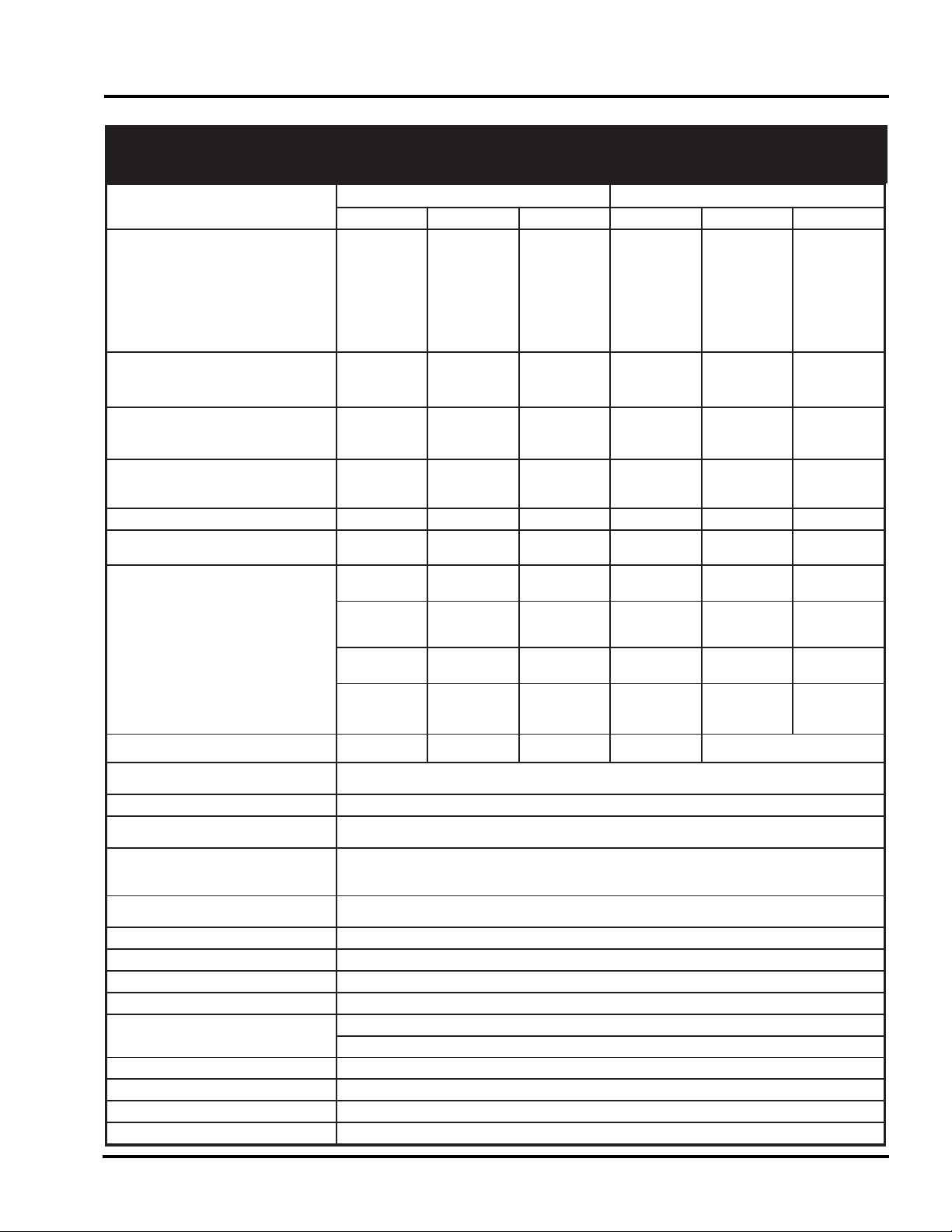
Specifications
2-2 October 2004 Maxim II Air Drill
eziSesaB sledoMemarF
ledoMemarF5
('92
)m48.8
('43
)m63.01
('93
)m98.11
('94
m49.41
)('55
)m77.61
('06
)m92.81
thgieW
)knahSnO-egdEhtiwsrekcaPleetS"2/13(
gnicapS"2/17- .sbl269,41.sbl930,71.sbl259,81.sbl752,52A/
/N
-gnicapSmc0.91 gk108,6gk547,7gk516,8gk084,11A/
/N
gnicapS"01- .sbl665,31.sbl520,51.sbl649,61.sbl055,2
sbl189,6
sbl108,82
-gnicapSmc4.52 gk661,6gk038,6gk307,7gk052,0
k462,2
k190,31
gnicapS"21- .sbl033,21.sbl151,41.sbl300,61.sbl909,0
sbl753,5
sbl492,72
-gnicapSmc5.03 gk506,5gk234,6gk472,7gk405,
k625,1
k604,21
htdiWgnikroW gnicapS)mc0.91("2/17-)m79.8("5'92)m94.01("5'43)m10.21("5'93)m60.51("5'94A/
/N
gnicapS)mc4.52("01-)m41.9('03)m76.01('53
)m91.21('04
)m42.51('0
m67.61('5
m92.81('06
gnicapS)mc5.03("21-)m48.8('92)m76.01('53
)m05.21('14
)m39.41('9
m67.61('5
m95.81('16
sknahSforebmuN )mc0.91("2/17-74553697A/
/N
)mc4.52("01-632484066
7
)mc5.03("21-925314945
6
htdiWemarF niaM-)m24.4("6'41)m24.4("6'41)m24.4("6'41)m24.4("6'4
m24.4("6'4
m24.4("6'41
gniWrennI-
gniWretuO-
)m92.2("6'7
A/N
)m50.3('01
A/N
)m18.3("6'21
A/N
)m50.3('01
)m92.2("6'7
)m18.3("6'21
)m92.2("6'7
)m18.3("6'21
)m50.3('01
htgneLllarevO)m28.7("8'52)m28.7("8'52)m28.7("8'52)m20.9("7'9
m20.9("7'9
m20.9("7'92
noitisoPtropsnarT htdiW-)m30.6("01'91)m30.6("01'91)m30.6("01'91)m68.6("6'2
m74.7("6'4
m74.7("6'42
thgieH-)m86.3("1'21)m92.4("1'41)m60.5("7'61)m33.5("6'7
m81.5('7
m81.5('71
seriT leehWrotsaCemarFniaM- IF51xL11)2(
DegnaRdaoL
IF51xL11)2(
DegnaRdaoL
IF51xL11)2(
DegnaRdaoL
IF51xL11)2(
DegnaRdaoL
IF51xL5.21)2(
FegnaRdaoL
IF51xL5.21)2(
FegnaRdaoL
leehWrotsaCemarFgniWrennI-
)gniwrep1(
51xL11)2(
gnitarylp6
)gniwrep1(
51xL11)2(
gnitarylp6
)gniwrep1(
51xL11)2(
gnitarylp6
)gniwrep1(
51xL11)2(
gnitarylp6
)gniwrep2(
51xL11)4(
gnitarylp6
)gniwrep2(
51xL11)4(
gnitarylp6
leehWrotsaCemarFgniWretuO-
)gniwrep1
(A/NA/NA/N 51xL11)2(
gnitarylp6
51xL11)2(
gnitarylp6
51xL11)2(
gnitarylp6
sleehWtropsnarTemarFniaM-
IF51xL11)4(
DegnaRdaoL
buHtloB6
IF51xL11)4(
DegnaRdaoL
buHtloB6
IF51xL11)4(
FegnaRdaoL
buHtloB8
IF51xL11)4(
FegnaRdaoL
buHtloB8
IF51xL5.21)4(
FegnaRdaoL
buHtloB8
IF51xL5.21)4(
FegnaRdaoL
buHtloB8
sgniWnosleehWrotsaClauDlanoitpOlanoitpOlanoitpOlanoitpO
gniWrennInodradnatS
gniWretuOroflanoitpO
sknaRforebmuN nrettaP"Z"wor4-gnicapS)mc0.91
("2/17
wor4-gnicapS)mc5.03("21&)mc4.52("01
msinahceMpirT knahs)mc1.5("2x)mc45.2(1htiwpirTnoihsuCgnirpS)gk081(bl004
snoitpOknahS nO-egdEdegroF
)slootegalliteergeD74()gnicapseloh)mc4.4("4/31(knahS'C'lanoitnevnoC
snoitpOleehWrekcaP
)gnicapS)mc4.52("01&)mc0.91("2/17(-rebbuRroleetS)mc1.5("2
)gnicapS)mc5.03("21&)mc4.52("01,)mc0.91("2/17(-rebbuRroleetS)mc9.8("2/13
gnicapS)mc5.03("21&)mc4.52("01(-rebbuRroleetS)mc4.
11("2/14 YLNO )
renepOotemarF ecnaraelClacitreV tnioPeoHralugeRhtiw"2/172-
srenepOefinK/toohSelbuoDhtiw"2/103-
gnicapSknaRotknaR )mc0.16("42
gnicapSknahSotknahS gnicaps)mc5.03("21no)mc4.19("63,gnicaps)mc4.52("01&)mc0.91("2/17no)mc2.67("03
htpeDemarF )sknar4()m39.1("67
sworraHraB-2 )YLNOgnicapS)mc4.52("01woR3(lanoitpO
sretluoC)nialProdelppiR(gnittuChsarT- )retemaid)mc8.05("02(-sertneC)mc2.67("03notnuoMwoRtnorF-lano
itpO
)nialP(rezilitreF- )tf06dna55noA/N()retemaid)mc8.05("02(-sertneC)mc8.05("02nognitnuoMmodnaR-lanoitpO
sreparcSduMrekcaP )srekcaPrebbuRdnaleetShtobroF(lanoitpO
srotcelfeDkcoR )gnicapS)mc5.03("21&)mc4.52("01,)mc0.91("2/17(lanoitpO
sthgiLytefaS dradnatS
niahCytefaS dradnatS
MAXIM II
Specifications and Options