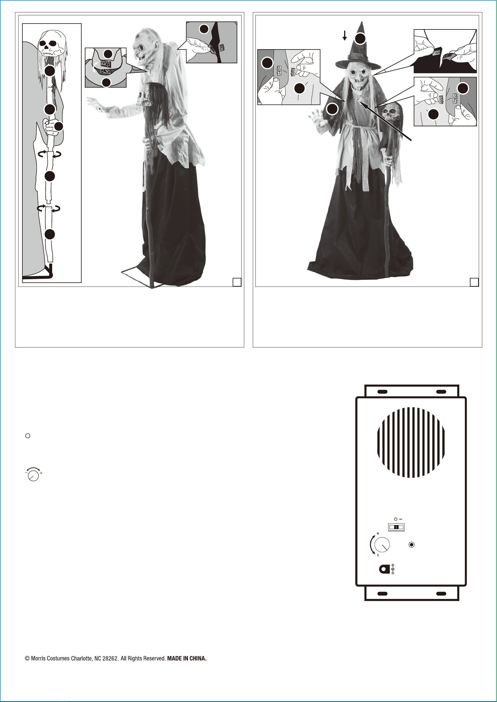
Assemble two pieces of the (M) Staff Poles together and twist counter-clockwise to secure. Set
the (M) Bottom Staff Pole onto the pole at the front of the (A) Base. Then slide the assembled
poles through the hole of the hand on the end of the (K) Left Arm, located on the top
of the assembled (M) Middle Staff Poles. Now assemble the (N) Skull Topper onto the
assembled (M) Staff Poles as shown and ensure the skull is facing forward.
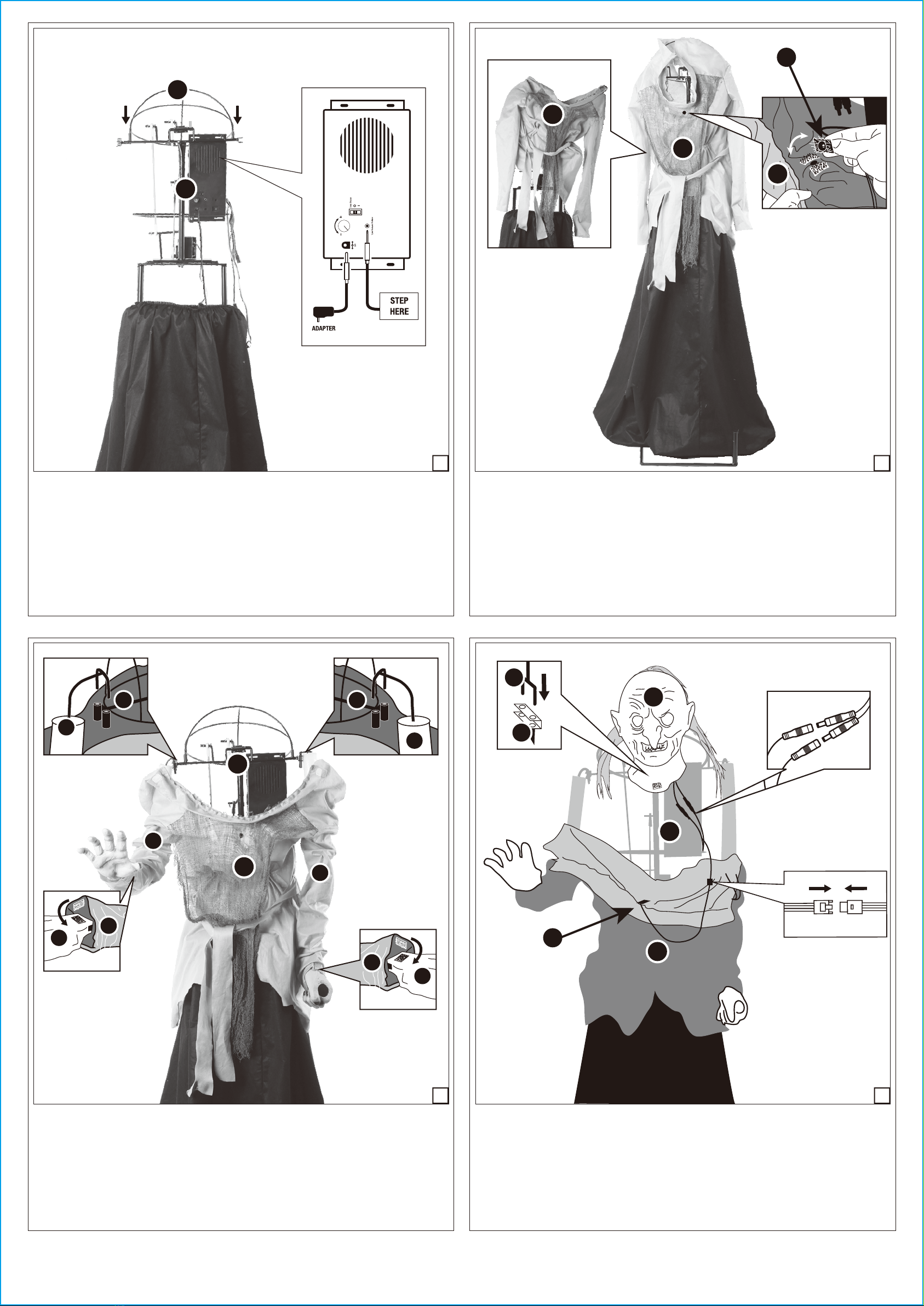
Secure the (H) Blouse under the chin and at the back with the hook and loop closures as shown
in Figure 7.1.
3/3
N
M
M
M
O
O
P
OH
H
Set the (O) Cape onto the shoulders of the witch. Secure the (O) Cape to the (H) Blouse with
the hook and loop closures at the front of the witch.
Place the (P) Hat onto the (L) Head as shown in Figure 8.1.
Your Lunging Witch With Digit Eyes is now fully assembled. Plug in and turn on to let the fun
begin!
STEP 8STEP 7
K
L
H
H
Sensor / Détecteur
5.9 V
Try me / Essaie-moi / Pruébame
7.1 8.1
This device complies with Part 15 of the FCC Rules. Operation is subject to the following two conditions: (1) This device may
not cause harmful interference, and (2) this device must accept any interference received, including interference that may
cause undesired operation.
CAUTION: Changes or modifications not expressly approved by the party responsible for compliance could void the user’s
authority to operate the equipment.
NOTE: This equipment has been tested and found to comply with the limits for a Class B digital device, pursuant to Part 15 of
the FCC Rules. These limits are designed to provide reasonable protection against harmful interference in a residential installa-
tion. This equipment generates, uses, and can radiate radio frequency energy and, if not installed and used in accordance with
the instructions, may cause harmful interference to radio communications. However, there is no guarantee that interference
will not occur in a particular installation. If this equipment does cause harmful interference to radio or television reception,
which can be determined by turning the equipment off and on, the user is encouraged to try to correct the interference by one
or more of the following measures: Reorient or relocate the receiving antenna, Increase the separation between the equipment
and receiver, Connect the equipment into an outlet on a circuit different from that to which the receiver is connected. Consult
the dealer or experienced radio/TV technician for help.
OPERATION INSTRUCTIONS:
1. Plug the Adapter into a standard power outlet and adjust the settings on the Function Control Box as desired.
2. Settings:
Sensor: This switch mode will activate lights, sound, and animation when the Infra-red (IR) sensor is activated and will operate
for 1 audio-cycle with each activation. The Infra-red (IR) sensor has a range of up to 2 m/6.5 ft. and will activate when
someone comes within an 80-degree angle from left-to-right, as well as from above and below.
/OFF/Try Me: This switch mode allows the item to be activated only if triggered by using a Step Here Try Me Activation Pad.
The item will operate for one audio cycle with each Try Me activation. Refer to Assembly Instructions Step 3 for further details.
I / ON : This switch mode will continuously operate the lights, sound, and animation of the item.
: Raise or lower the volume using the volume control turn dial, turn all the way down to turn the volume off.
Sensor Here