Contents
Chapter
I.
Introduction
...........................................................
1
1-1.
Introduction
............................................................................
2
I-
2.
Specifications
.........................................................................
3
Chapter
II.
Hardware
Installation
...........................................
5
II-
l.
Installation
Guide
..................................................................
6
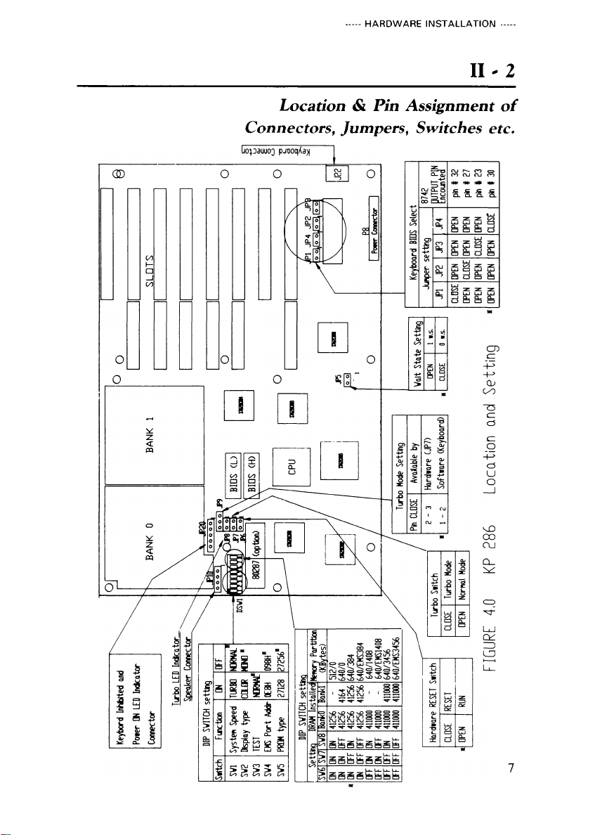
II-
2.
Location
and
Pin
Assignment
of
Connectors,
Jumpers,
S itches,
etc
...................................
7
II-
3.
Jumpers
and
S itch
Settings
...............................................
11
Chapter
III.
Software
Setup
.....................................................
17
III-
l.
Real
Time
Clock
and
CMOS
RAM
Setup
.............................
18
III-
2.
Example:
Ho
to
Preformat
a
Hard
Disk
ith
AMI
BIOS
’
s
Diagnostics
Program
........................................
23
III-
3.
EMS
Driver
Setup
.................................................................
31
Chapter
I .
Technical
Reference
............................................
35
IV-
l.
Microprocessor
.......................................................................
36
IV-
2.
System
Board....
....................................................................
37
Chapter
.
Appendix
.................................................................
41
V-
l.
Po er
On
Self
Test
<POST>
Error
Message
....................
42
V-
2.
Partitioning
and
Formatting
a
Hard
Disk
ith
MS-DOS
................................................................................
44
V-3.
Circuit
Diagrams
....................................................................
47
V-4.
Quick
Reference
Guide
for
DIP
S itch
&
Jumper
Setting
.....................................................................................
66
Western
Digital,
IBM,
PC,
AT,
XT,
PS/2,
OS/2,
Intel,
MS-DOS,
XENIX
and
Novell
are
trademarks
of
their
respective
companies.