Mosa DS-512100-R01 User manual

LITHIUM-ION BATTERY PRODUCT
USER MANUAL
DS-512100-R01

- 1 -
REVISION RECORDS
NO.
Revision
Author
Revision Of Content
Revision Time
1
V1.0
First Release 07-24-2022
2
3
4
5

- 2 -
MANUAL EXPLANATION
▶COTENT EXPLANATION
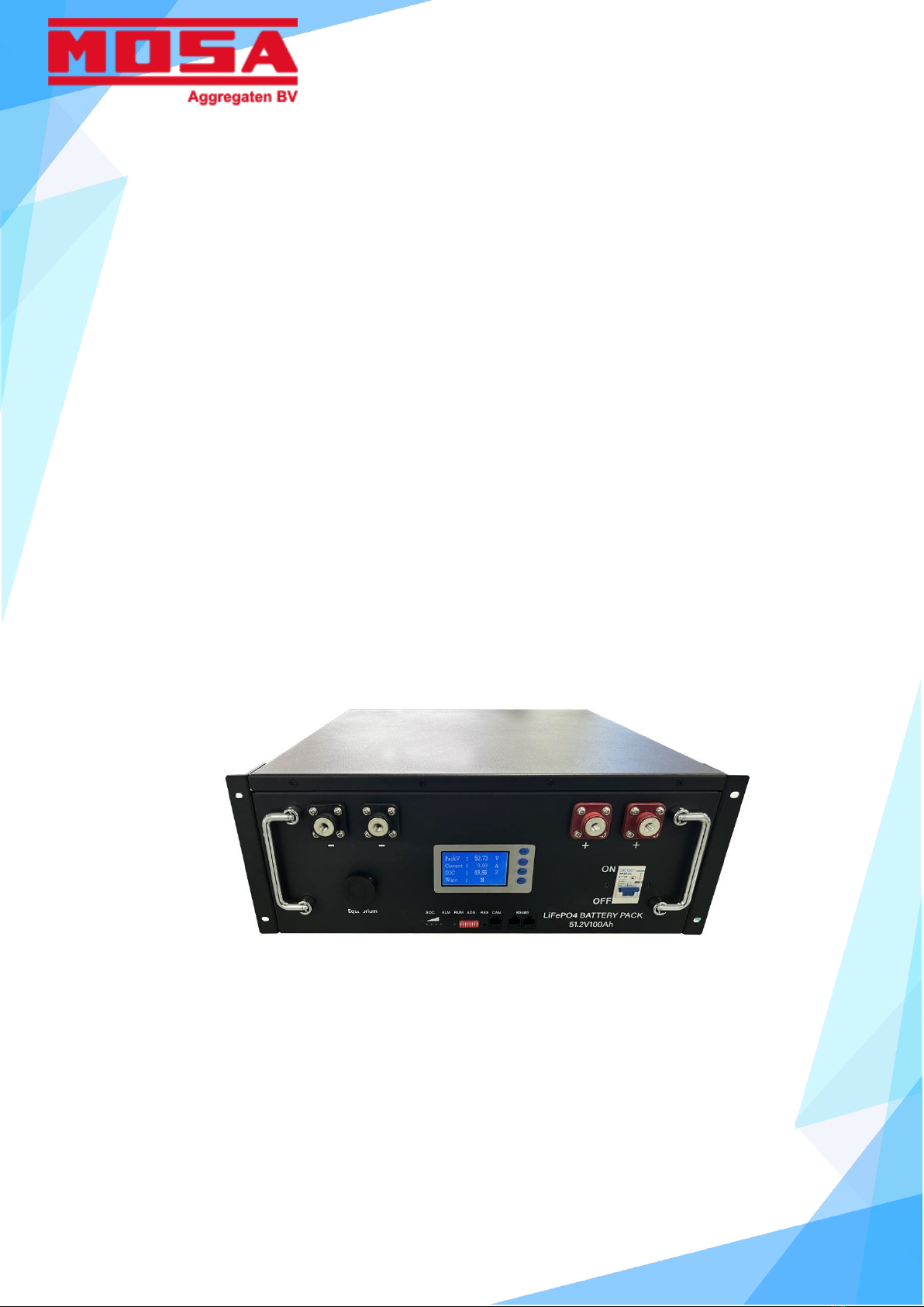
DS-512100-R01 series is Lithium-ion phosphate battery module which designed for residential
energy storage applications. This battery module integrated with intelligent BMS inside, support
communicate with ON/OFF grid solar power inverter, has big advantages on safety, cycle life,
energy density, temperature range and environmental protection. This product user manual
describes the parameters and installation details.
●
BEFORE YOU START
Read all the safety information provided in this document prior to install and/or operate the
equipment. Contact Customer Support immediately for a free consultation if you have any questions
about the handling, operation and safe use of the battery.
To handle or operate with battery system:
•
You must be qualified for electrical work;
•
Before you operate the battery module, you should be better trained and read the manual
carefully;
•
Remove any possible metallic shorting risk of Jewel, Watches, Pens. Metal bars and frames;
•
All tools must be insulated
Chapters Contents
1. Safety cautions Safety rules and precautions
2. General information Battery parameters
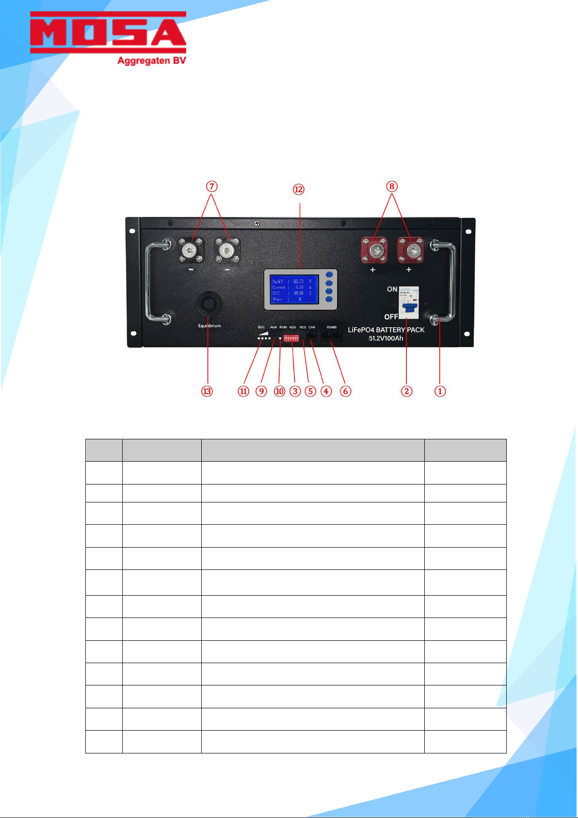
3. Panel features Introduce the interface function
4. Packing list Packing list
5. Installation Installation and operation
6. Shipping, Storage, and Disposal Shipping, Storage, Maintenance And Disposal

- 3 -
1SAFETY CAUTIONS
SAFETY SYMBOLS
Symbol Definition
Important safety information will follow.
DO NOT dispose of battery in a fire.
Recycle or dispose of Lithium batteries in accordance with local
Laws/regulations.
DO NOT dispose of battery in the trash.
PRECATIONS
Please read and comply with the following conditions of installation and use of the battery,
incorrect installation using the battery may cause personal injury or damage to the product.
1.
DO NOT throw the battery into water. Store batteries in cool and dry environment when not in
use.
2.
DO NOT put the battery into fire or heat the battery, so as to avoid explosion or other dangerous
events.
3.
When charge the battery,please choose specialized charging equipment, and follow the correct
procedures, do not use unqualified chargers.
4.
DO NOT reverse positive and negative terminals, do not connect the battery directly to AC power ,

- 4 -
avoid battery short circuit.
5.
DO NOT using batteries from different manufacturers or different kinds, types together ,and do
not mixed use old batteries and new batteries.
6.
DO NOT use the battery when it becomes hot, bulges, deforms or leaks.
7.
DO NOT puncture the battery by nail or other sharp objects; Do not throw, stamp on, impact or
hit the battery.
8.
DO NOT open or try to repair the battery when it is defective. Warranty invalid if the battery
repaired or disassembled.
9.
Batteries are half charged before shipment, Don’t use the battery if it’s hot, bulge, or smell
abnormal and so on, and report to after-sale dept. immediately.
10.
If you need storage the battery for a long time, please charge and discharge the battery every
three months to ensure the best performance, and the best state of charge for storage is
between 50%~60%.
11.
Please use the battery in the temperature range which defined in the manual.
12.
The state of charge of batteries is 50% before shipment, please charge the battery beforeusing.
Note: If you have some special technical problems which not mentioned above, please
contact technical staff.

- 5 -
2GENERAL INFORMATION
Model/Parameters DS-512100-R01
Basic
Normal Voltage [V] 51.2
Normal Capacity [Ah] 100
Operating Voltage [V] 40-58.4
Rated energy [kWh] 5120
Battery Type Li-ion(LiFePO4)
Ah Efficiency [%] 97
Wh Efficiency [%]
94
Standard Power [kW] 10
Recommended Charging current [A] 50
Maximum Discharging current [A] 100
Dimension & Weight
Dimension(L*W*H) [mm] 442*425*178
Weight [Kg] ≈45kg
Communication
Battery to Inverter CAN
Battery to Battery/BMS RS485
Capacity Indicator LCD screen
Switch ON/OFF Button
Environment
Operating Temperature [℃] -10 to 55
Relative Humidity [%] 5 to 95
Altitude [m] Below 4000
Standard Comply
Safety CE, ROHS
Hazardous Materials Classification Class 9/UN3480
Transport Testing Requirement UN38.3
Cycle Life [85% DOD] ≥5000
Warranty [Year] 3

- 6 -
3PANEL FEATURES
NO. Name Function Remarks
1
Handle For carrying,handling
2
Power
DC-200A Air Switch
3
ID Assign address of every model See Table 3.4
4
CAN CAN Communication interface
5
RESET Power on for the first time Activate BMS
6
Battery Comm
RS485
Battery inter-comm when connect in parallel
7
Terminals Positive
8
Terminals Negative
9
ALM Alarming indicates LED 4 pcs green LED
10
RUN Operating indicates LED
11
SOC The state of charge
12
LED isplay Four keystrokes
13
Equilibrium

- 7 -
ID Arrangement
ID arrangement should be set when parallel use and steps shows below.
Maximum parallel of DS-512100/51200is 16.
Assignments of ID address
Note: In the table 1, code bits are in accordance with the control panel ID code corresponding to the
binary digit, dial up stands for "OFF ", dial down stand for " ON ", the left dial is low digit, the
right dial is high digit, encoding in the range of 1~16, which can support up to 16 modules
cascade. All coded according to the table, followed by analogy. If you need more modules in
parallel, please tell us, we will design it to meet your requirement.
BMS ID 01 is the master BMS.
If you use only single battery, please set the ID to be 01.
If you use battery modules in parallel, set one battery module to be 01, and other ID are
different, and make sure each ID is unique in the string.
Code
Address
Assign
Remarks
1
2
3
4
5
6
7
8
OFF
OFF
OFF
OFF
ON
ON
ON
ON
1
Model 1
ON
OFF
OFF
OFF
OFF
OFF
OFF
OFF
2
Model 2
OFF
ON
OFF
OFF
OFF
OFF
OFF
OFF
3
Model 3
ON
ON
OFF
OFF
OFF
OFF
OFF
OFF
4
Model 4
OFF
OFF
ON
OFF
OFF
OFF
OFF
OFF
5
Model 5
ON
OFF
ON
OFF
OFF
OFF
OFF
OFF
6
Model 6
OFF
ON
ON
OFF
OFF
OFF
OFF
OFF
7
Model 7
ON
ON
ON
OFF
OFF
OFF
OFF
OFF
8
Model 8
OFF
OFF
OFF
ON
OFF
OFF
OFF
OFF
9
Model 9
ON OFF OFF ON OFF OFF OFF OFF 10 Model 10
OFF ON OFF ON OFF OFF OFF OFF 11 Model 11
ON ON OFF ON OFF OFF OFF OFF 12 Model 12
OFF OFF ON ON OFF OFF OFF OFF 13 Model 13
ON OFF ON ON OFF OFF OFF OFF 14 Model 14
OFF ON ON ON OFF OFF OFF OFF 15 Model 15
ON ON ON ON OFF OFF OFF OFF 16 Model 16

- 8 -
Communication ports
CAN and RS485 are used for communication with inverter.
Battery comm used for battery in parallel ID arrangement.
CAN Communication interface definition
Pin-No. Definition Pin-No. Definition
PIN-1 NC PIN-5 CAN CAN_L
PIN-2 NC PIN-6 NC
PIN-3 NC PIN-7 NC
PIN-4 CAN CAN_H PIN-8 NC
CAN_H CAN_L
RS485 Communication interface definition
Pin-No. Definition Pin-No. Definition
PIN-1 RS485 B-(T/R-) PIN-5 NC
PIN-2 RS485 B-(T/R-) PIN-6 NC
PIN-3 NC PIN-7 RS485 B-(T/R-)
PIN-4 NC PIN-8 RS485 B-(T/R-)
RS485 B- RS485 A+ RS485 B-

- 9 -
4PACKING LIST
Parts List
Item Item name Qty
1
DS-512100-R01 battery module
1
2
Power cable between battery and Inverter
(MPC 100A 600V-16mm²_1m)
2
3
Communication cable_1m
1
4
User manual
1
5
Carton
1

- 10 -
5INSTALLATION
Prepare to Install
The installation, operation and maintenance of DS-48200-F02 lithium-ion phosphate battery
system must be performed by trained and qualified professional personnel. Before installation
and use, please carefully read the product safety precautions and related operating rules.
Strictly abide by the following safety rules and local safety regulations, otherwise may cause
personal injury or damage to the product.
1.
Make sure that the load equipment to be connected with the battery system is in good
condition and free from defects;
2.
Before installation, make sure that the power supply system is under shut down state,
while the battery system is also under shut down state;
3.
All the electricity cables must have corresponding grade of insulation, Please ensure that
no exposed cables;
4.
Make sure that the battery and power system are reliable grounding.
Installation environment
The requirement of installation environment is shown in table.
Type Requirement
Working Temperature Working Range:-20℃~+60℃
Storage Temperature -20℃ ~+60℃
Relative Humidity <95%
Atmospheric Pressure 86kPa~106kPa
Site Requirements No conductive dust and corrosive gas, no vibration. Keep away from
heat and flame

- 11 -
Tools and materials
May use the tools and information are shown in table.
Name Name
User manual Oblique mouth clamp
Screw driver Multimeter
Wrench Ammeter
Pincers Insulating tape
Wire stripping pliers Electrostatic prevention Bracelet
Wristband
Battery check
1.
On the installation site, check the battery packaging to make sure it's intact;
2.
Check battery box according to the packing list, make sure all the material is complete, if
any damaged, please fill in the receipt;
3.
Please be careful while handling batteries, avoid any damage.
Installation
The battery is rack installed , steps shows below.
CAUTIONS
When begin to install the battery system, you should pay attention to the following matters:
1.
Installation space and load bearing. Make sure that there are sufficient fixed components to
install the battery system, and to ensure that the battery mounting bracket or the cabinet be
strong enough to bear the weight.
2.
Cable specifications. To ensure that the use of the connection of the power supply line can
match the maximum current requirements of equipment operation.

- 12 -
3.
Project layout. Ensure the whole construction process of power equipment, batteries and
other reasonable layout.
4.
Wiring layout. Ensure that the wiring reasonable, orderly; and consider the moisture-proof,
corrosion prevention.
5.
The whole installation process should wear anti-static wristband.
6.
The installation site should be at least two or more people to operate.
CAUTION:Please ensure the installation site safe before installation.
Caution:Single battery module is about 45kg. If without handling tools must have
more than 2 men to carry it.
Step1. Connection Terminals and Interfaces Overview.
1.
Connect to Inverter with power cable and communication cable.
2.
More than one battery module to parallel, Set the ID following the ID arrangement
table. Connect the power cable in parallel by power cables and connect communication
cables in battery comm interface with communication cables . Connect the first or last
battery module RS485/CAN interface to the PC monitor or SMPS or UPS controller.
3.
Push the “ON/OFF” button to start the battery system.
4.
Check the battery data and ensure the battery is on normal operation.
Caution :If you have any questions about the installation, please stop and contact
technical support immediately. If the battery does not start or control panel ALM lights, please
disconnect the power line inspection and re-install the start, if still cannot solve please contact
technical support, avoid damage to equipment or cause accidents.

- 13 -
6SHIPPING, STORAGE, AND DISPOSAL
Shipping
According to the provisions of the product can be used in general means of conveyance, but
should avoid throwing, rainfall, strong radiation and corrosion erosion. during transportation,
please prevent the collision and strong vibration.
Storage
Storage device in the indoor storage, the ambient air temperature is 0 ℃ to + 45℃, the
average monthly relative humidity of not more than 90%, the ambient air without corrosive
and flammable and explosive gas; storage warehouse should be ventilated, free of alkaline,
acidic substances and other corrosive gases, without a strong mechanical vibration, shock,
and without strong electromagnetic field and direct sunlight. Capacity was maintained at 50%
to 60% stores, and charging the battery every 6 months.
Troubleshooting
No.
Fault Analysis Solution
1
No DC output Low voltage protection Charge before use
2
No enough discharging time No enough capacity or not
charged to full
Confirm maintenance or replace
battery
3
ALM always bright, cannot
charge or discharge
Battery or BMS fail
Connect to Inverter/PC
monitoring or check the data on
LCD Screen and find the reason
Caution:If the battery cannot operate normally, please do not disassemble the battery
without technical instructions.
Table of contents
Other Mosa Camera Accessories manuals