Motion Impossible AGITO User manual

AGITO
1
Motion Impossible Ltd. www.Motion-Impossible.com
+44 1454 501010 1 AGITO Owners’ Manual v1.0 Firmware r3
OWNERS MANUAL
Firmware Version: r3
AGITO

AGITO
2
www.Motion-Impossible.com Motion Impossible Ltd.
AGITO Owners’ Manual v1.0 Firmware r3 2 +44 1454 501010
DOCUMENT REVISION HISTORY
REVISION: DATE: DESCRIPTION:
1.0 July 2019 Initial Document Release – Firmware Release r3.0

AGITO
3
Motion Impossible Ltd. www.Motion-Impossible.com
+44 1454 501010 3 AGITO Owners’ Manual v1.0 Firmware r3
TABLE OF CONTENTS
DOCUMENT REVISION HISTORY ...............................................................................................2
TABLE OF CONTENTS ...............................................................................................................3
1.
INTRODUCTION ...........................................................................................................5
Disclaimer..................................................................................................................... 5
Warnings ..................................................................................................................... 5
General Safety .............................................................................................................. 6
Batteries & Charging Safety Advice ................................................................................. 6
Warranty...................................................................................................................... 6
2.
CASE CONTENTS, DIMENSIONS & SHIPPING WEIGHTS .................................................7
CORE & MASTER .......................................................................................................... 7
Sports Drive-Ends ........................................................................................................... 7
V-Con PRO.................................................................................................................... 8
Tower........................................................................................................................... 8
Trax Drive-Ends.............................................................................................................. 8
3.
AGITO CORE OVERVIEW ..............................................................................................9
Introduction................................................................................................................... 9
CORE Dimensions.......................................................................................................... 9
Battery Slots .................................................................................................................. 9
CORE RF Module Socket............................................................................................... 10
CORE I/O Ports........................................................................................................... 10
Payload Mounting........................................................................................................ 10
4.
DRIVE-ENDS OVERVIEW ..............................................................................................11
Sports Drive-Ends ......................................................................................................... 11
Trax Drive-Ends............................................................................................................ 11
5.
PAYLOAD OVERVIEW..................................................................................................12
V-Con PRO.................................................................................................................. 12
Tower......................................................................................................................... 12
Mitchell Mount ............................................................................................................ 12
V-Con Stacking Risers................................................................................................... 12
6.
MASTER CONTROLLER OVERVIEW ...............................................................................13
Operational Controls Layout.......................................................................................... 13
Definitions................................................................................................................... 13
Throttle INPUT..................................................................................................... 13
Speed Limit......................................................................................................... 13
ACC.................................................................................................................. 13
DEC................................................................................................................... 13
Function Switch ................................................................................................... 14
Steering Input ..................................................................................................... 14
Steer Limit........................................................................................................... 14
Mode Switch ...................................................................................................... 14
Menu................................................................................................................. 14
MASTER I/O Connections............................................................................................. 14
Safety Functions........................................................................................................... 14
7.
MASTER USER INTERFACE............................................................................................15
Menu Structure (Firmware r3) ........................................................................................ 15

AGITO
4
www.Motion-Impossible.com Motion Impossible Ltd.
AGITO Owners’ Manual v1.0 Firmware r3 4 +44 1454 501010
Initial Start-up / Calibration Screen ....................................................................... 15
Home Screen ...................................................................................................... 15
Drive-Ends Menu ................................................................................................. 17
User Profiles Menu............................................................................................... 18
System Menu ...................................................................................................... 18
Moves Menu....................................................................................................... 19
8.
SETTING UP AGITO.....................................................................................................20
Inserting the RF Modules ............................................................................................... 20
Inserting Drive-Ends...................................................................................................... 21
Attaching Wheels to the Drive-Ends................................................................................ 21
Setting Wheel tracking ................................................................................................. 22
Attaching Payload: V-Con PRO...................................................................................... 22
Attaching Payload: V-Con Stacking Risers ....................................................................... 22
Adjusting / Tuning V-Con PRO ...................................................................................... 23
Adjusting Sports-Ends Suspension .................................................................................. 23
Adjusting the Kick-up.................................................................................................... 24
Inserting and Removing Batteries from the CORE ............................................................. 24
Attaching Cheese-plate................................................................................................. 24
Attaching Payload: Tower............................................................................................. 25
Attaching Camera Gimbal to Tower............................................................................... 25
Attaching Payload: Mitchell Mount................................................................................. 25
9.
CONFIGURING AGITO ...............................................................................................26
Turning on AGITO ....................................................................................................... 26
Configuring AGITO setup ............................................................................................. 26
Driving AGITO ............................................................................................................ 26
Motor Mode ....................................................................................................... 26
Throttle Mode ..................................................................................................... 27
Braking and Emergency Stop Function ................................................................... 28
Steering Modes................................................................................................... 28
Moves Mode ...................................................................................................... 28
10.
OPERATING AGITO.....................................................................................................29
Drive Dynamics ........................................................................................................... 29
First Use ............................................................................................................. 29
Start Up Calibration............................................................................................. 29
Checking Tracking / Wheel Alignment .................................................................. 29
Kick Up.............................................................................................................. 30
11.
FIRMWARE UPDATES...................................................................................................31
12.
MAINTENANCE..........................................................................................................32
Serviceable Parts ......................................................................................................... 32
Sports-Ends Shocks .............................................................................................. 32
13.
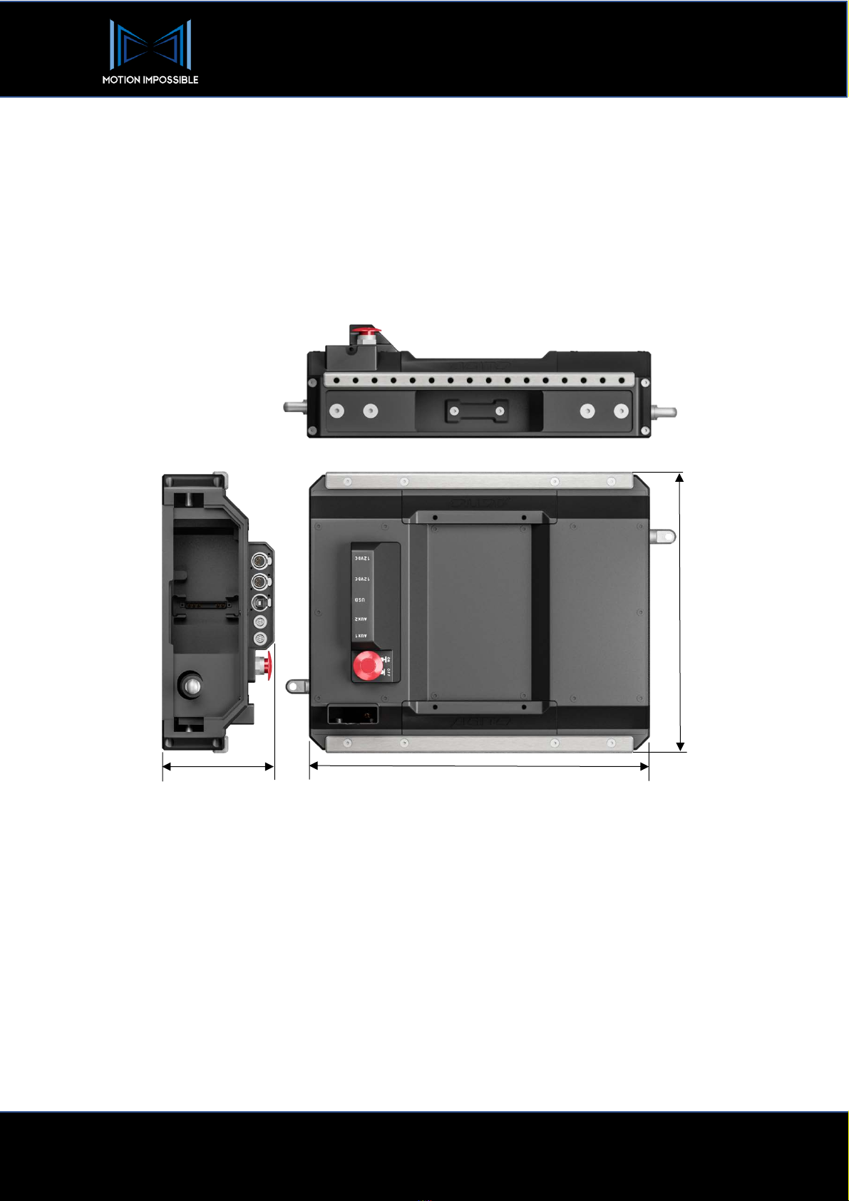
SPECIFICATIONS, DIMENSIONS & CONNECTOR PIN-OUTS ..........................................33
General Specifications ................................................................................................. 33
Example Dimension Diagrams ....................................................................................... 34
Sports Drive-end, with Dolly / Multi-terrain Wheel ................................................... 34
Sports Drive-end, with Monster Wheel ................................................................... 34
Connector Pin-Outs ...................................................................................................... 35
CORE Interface I/O Connectors ............................................................................ 35
MASTER Controller Interface I/O Connectors.......................................................... 36
RF Module Pass-through Box ................................................................................. 36
AGITO Tower Connections................................................................................... 37
Further Support............................................................................................................ 38
Distributor Service Centres.................................................................................... 38

AGITO
5
Motion Impossible Ltd. www.Motion-Impossible.com
+44 1454 501010 5 AGITO Owners’ Manual v1.0 Firmware r3
1. INTRODUCTION
This document provides information to assist with the setup, installation and safe operation of
MOTION IMPOSSIBLE’S AGITO Modular Dolly System.
IMPORTANT:
Please read this disclaimer and warning carefully and review the
AGITO Owner’s Manual prior to use.
If you have any questions, please contact
support@motion-impossible.com
before operating.
Always ensure that you have the current version of
this Owner’s Manual, downloadable from
www.motion-impossible.com/downloads
DISCLAIMER
Motion Impossible Ltd reserves the right to revise this Owner’s Manual and make changes from time to
time without obligation to notify any persons of such revisions or changes. In no event shall Motion
Impossible Ltd, its employees or authorized agents be liable for any damages or losses, direct or
indirect, arising from the use of any technical or operational information contained in this document.
Every precaution has been taken in the preparation of this Manual. Nevertheless, Motion Impossible
Limited assumes no responsibility for errors or omissions or any damages resulting from the use of the
information contained herein.
WARNINGS
Throughout this manual important safety notices are highlighted, as follows:
This is a General Warning. Not
following these can cause damage
to the product.
This is a Health & Safety Warning.
Not following these can cause
harm to you or others.

AGITO
6
www.Motion-Impossible.com Motion Impossible Ltd.
AGITO Owners’ Manual v1.0 Firmware r3 6 +44 1454 501010
GENERAL SAFETY
• It is your responsibility to learn how to safely operate AGITO.
• It is your responsibility to perform a full system check of AGITO prior to every use.
• Always maintain awareness of your surroundings when operating AGITO.
• AGITO is a tuned system with custom components. Modification, removal, or substitution of
AGITO components will void the warranty.
• ALWAYS use factory specified replacement parts and accessories, if in doubt contact:
support@motion-impossible.com
• Do not disable any safety features on the system.
• Whilst the AGITO is designed to operate in various environments, the system is NOT Ingress
Protection (IP) rated. Operating AGITO, its component parts and accessories in adverse
environmental conditions is entirely at the operator’s risk.
By using AGITO, you acknowledge that you have read, understand, and agree to this disclaimer. You
agree that you are solely responsible for your conduct while using AGITO and for any direct or indirect
consequences that may result from its use.
BATTERIES & CHARGING SAFETY ADVICE
You must read these safety instructions and warnings carefully before charging or using your AGITO
Battery Pack. Improper use may result in damage to the batteries, severe personal injury, and even fire.
• Do not leave AGITO Battery Packs and charger unattended when in use.
• If a battery pack becomes or appears damaged STOP using it immediately.
• Never disassemble, modify, puncture, shock, crash, short circuit, and/or expose Battery Packs
to a flame. Leakage, smoke emission, ignition, explosion or fire can occur, which may result in
personal injury or property damage.
• Never allow an electrical short between the battery’s positive and negative terminals.
By purchasing an AGITO Battery Pack, the buyer agrees to bear all responsibilities of the risks and not
hold Motion Impossible Ltd, its owners and employees, its distributors, and/or its retailers responsible
for any accidents, injury to persons, and property damage. If you do not agree to these conditions,
please return the AGITO Battery Pack to the place of purchase in a new and unused condition.
WARRANTY
AGITO comes with a return-to-base 12-month Warranty from the original date of shipment.
Please note that opening the AGITO CORE, MASTER or any other component will void your Warranty
.

AGITO
7
Motion Impossible Ltd. www.Motion-Impossible.com
+44 1454 501010 7 AGITO Owners’ Manual v1.0 Firmware r3
2. CASE CONTENTS, DIMENSIONS &
SHIPPING WEIGHTS
CORE & MASTER
ID:
Dimensions (HxWxD):
Shipped Weight:
CORE Case
550 x 820 x 430mm
32Kg
No.
Part Name
1
AGITO CORE
2
RF Antenna
ID:
Dimensions (HxWxD):
Shipped Weight:
Accessories & Battery Case
TBC
32Kg
No.
Part Name
3
2x AGITO Chargers
4
4x AGITO 99Wh Batteries
5
MASTER Controller
6
AGITO Toolkit
7
8x Drive End Bolts
8
4x Accessory Rail Bolts
9
RF Antenna
10
AGITO Update Cable
SPORTS DRIVE-ENDS
ID:
Dimensions (HxWxD):
Shipped Weight:
CORE Case
550 x 820 x 430mm
32Kg
No.
Part Name
1
2x AGITO Sports Ends
2
4x Wheel Nuts
3
Wheel Nut Spanner
4
4x Sports Lock-out Bars

AGITO
8
www.Motion-Impossible.com Motion Impossible Ltd.
AGITO Owners’ Manual v1.0 Firmware r3 8 +44 1454 501010
V-CON PRO
ID:
Dimensions (HxWxD):
Shipped Weight:
V-Con PRO Case
TBC
TOWER
ID:
Dimensions (HxWxD):
Shipped Weight:
Tower Case
TBC
TBC
Details will be updated when TOWER is released
TRAX DRIVE-ENDS
ID:
Dimensions (HxWxD):
Shipped Weight:
Trax Drive-Ends Cases (x2)
TBC
TBC
Details will be updated when TRAX is released
No.
Part Name
1
V-CON PRO Isolator
2
V-CON Adaptor Plate
3
8x ISO Dampeners
4
Space for Wheels
The V-CON PRO must be fully
lowered using the payload adjuster
knob before placing into the case.

AGITO
9
Motion Impossible Ltd. www.Motion-Impossible.com
+44 1454 501010 9 AGITO Owners’ Manual v1.0 Firmware r3
3. AGITO CORE OVERVIEW
INTRODUCTION
The CORE is the heart of your AGITO Modular Dolly System, within this module is contained all of the
power management, RF and steering drivers.
CORE DIMENSIONS
BATTERY SLOTS
The Battery Connection uses our own proprietry 48v Li-Ion battery packs. Only Motion Impossible
approved battery packs should be used to prevent damage to the system.
The system can run off a single battery, but for optimum runtime the chassis should be fitted with 2
batteries, fitted one on each side, that can be hot swapped to keep the system fully powered during a
battery change. Always make sure to run batteries of the same charge level to ensure optimum
runtimes.
Although the core can power up and down almost instantly, if you are powering accessories from the
12v chassis power outputs then they will also receive uninterrupted power during a battery change
using the hot-swap method.
380mm
460mm
110mm
16x 3/8” threaded 1 inch/25.4mm pitch

AGITO
10
www.Motion-Impossible.com Motion Impossible Ltd.
AGITO Owners’ Manual v1.0 Firmware r3 10 +44 1454 501010
CORE RF MODULE SOCKET
The system by default comes with a 2.4 GHz system. The RF module is fixed via a single bolt, simply
unscrew this to remove the RF and swap for other RF modules (sold separately) when required.
If required a Pass-Through module is also available which enables the use of third-party solutions. This
unit provides (see section 10 for pin-outs):
• Data (RS-232)
• 12v Power (1A max)
CORE I/O PORTS
• 2x 12v DC Outputs – 4 Pin XLR connectors with a shared 2A load, only designed for
lightweight accessories that draw low power, such as RF or video transmission.
• USB Connector – Not in Use (for future expansion).
• 2x AUX Ports – Wired for multiple interface types. Some of our accessories utilise this
connectivity. AUX1 is also the port you use to update the software in the chassis when new
improvements are released.
PAYLOAD MOUNTING
• Payload mounting is provided via the 2 mounting rails on each side of the chassis. The
threaded holes are 3/8 inch spaced at 1-inch intervals. These allow for the fitting of all our
current and future stabilisation / camera mounting solutions.
Please ensure you use the correct RF module for your territory, we provide a range of
options. Please contact us for more information.

AGITO
11
Motion Impossible Ltd. www.Motion-Impossible.com
+44 1454 501010 11 AGITO Owners’ Manual v1.0 Firmware r3
4. DRIVE-ENDS OVERVIEW
SPORTS DRIVE-ENDS
Sports Drive-Ends are our Free-roaming drive module, with multiple Wheel-type options:
Dolly Wheel
Multi-terrain Wheel
Monster Wheel
Track Wheel
Snow-Trax
Details to follow
Details to follow
TRAX DRIVE-ENDS
Details to follow shortly

AGITO
12
www.Motion-Impossible.com Motion Impossible Ltd.
AGITO Owners’ Manual v1.0 Firmware r3 12 +44 1454 501010
5. PAYLOAD OVERVIEW
V-CON PRO
V-Con PRO is our low-level isolation mount, designed for camera/gimbal
packages of up to 32Kg. With a combination of vertical dampening and
vibration isolation, V-Con PRO keeps the camera low to the ground and is
ideal for high speed, dynamic moves when a low lens height and centre
of gravity are important.
TOWER
AGITO Tower is our remote pedestal column, which enables on-shot
height adjustment with camera/gimbal packages of up to 20Kg on Sports
and 32Kg on Trax. The design allows for up to 700mm (27.5 inches) of
travel from a starting height of approximately 750mm (29.5 inches)
subject to Drive-end (see Specifications Section of this manual).
MITCHELL MOUNT
Provided as part of the Tower package (or available as an optional extra)
the Mitchell Mount is a non-isolated fixture – further details to be released
soon.
V-CON STACKING RISERS
Available as an option extra, the risers are designed to lift the V-Con up above the AGITO chassis –
further details to be released soon.

AGITO
13
Motion Impossible Ltd. www.Motion-Impossible.com
+44 1454 501010 13 AGITO Owners’ Manual v1.0 Firmware r3
6. MASTER CONTROLLER OVERVIEW
OPERATIONAL CONTROLS LAYOUT
DEFINITIONS
THROTTLE INPUT
:
Gives forward, reverse & brake in one control. When applying brake, i.e. opposite
throttle to the direction you are currently moving, you are forcing the chassis to stop with 100%
deceleration.
Whilst in the menus the throttle also functions as an up/down control.
SPEED LIMIT
- Maximum speed limit:
This control is located on the top left corner and can be operated
during a movement. The throttle input and chassis speed cannot exceed the value set by this control.
The current maximum speed setting is displayed on the LCD. When in the menus it also functions as a
value control. Behind this control on the rear of the MASTER is a button to make a menu selection.
ACC
- Acceleration limit:
Sets the maximum rate of acceleration you can achieve with a full throttle
input. A higher value allows a faster acceleration rate.
DEC
- Deceleration rate control:
Adjusts the rate of deceleration when the throttle control is released to
neutral while moving. A higher value increases the rate of deceleration and is recommended, a lower
When turning on the MASTER Controller be careful not to press any button other than the power
switch, specifically the Throttle Input. On start-up the controller runs through a calibration process,
if the Throttle Input is not centered then the AGITO may accelerate unexpectedly.
The calibration process finishes when the main menu screen appears.

AGITO
14
www.Motion-Impossible.com Motion Impossible Ltd.
AGITO Owners’ Manual v1.0 Firmware r3 14 +44 1454 501010
value decreases the rate of deceleration (resulting in a longer braking distance!). When applying the
brake, i.e. opposite throttle to the direction you are currently moving, you are forcing the chassis to stop
with 100% deceleration, no matter what figure is shown as the DEC value.
FUNCTION SWITCH
– Emergency Brake:
In Firmware R3, this switch is set to Emergency Brake,
switching this during operation will command the AGITO to stop as quickly as possible and hold the
AGITO in position. There are three modes of operation, AUTO, UP & DOWN, these are explained later
in the manual.
STEERING INPUT
- Steering mode control:
Turns the chassis according to the steering mode selected
(does not apply when Trax-Ends are fitted).
Whilst in menus, the steering input also functions as a left/right control.
“2-4-C” - Steering mode:Control switches between 3 steering modes:
• 2-wheel steering: front wheel pair steers
• 4-wheel steering: front and rear wheel turn in opposite directions reducing the turning
circle and pivots the chassis around the middle during a turn.
• Crab steer: front and rear wheels turn the same way resulting a sideways sliding movement
instead of a turn
STEER LIMIT
- Steering lock limit:
Sets the maximum steering angle possible with a full left or right
steering input. Good for accurate curves and reducing sensitivity during high-speed movement
MODE SWITCH
- Film & Free mode:
This switch is designed to allow you to setup and quickly swap
between 2 types of movement behaviour. For example, a slow and very controlled camera movement
on “Film” mode, and a faster manoeuvring mode in “free” mode. The system automatically remembers
the last settings being used before the modes are changed.
MENU
- Press to enter the menu options:
Rotate to select the desired function. Please see section Xfor
menu structure and feature list.
MASTER I/O CONNECTIONS
• AUX PORTS: On the Rear of the master are two auxiliary LEMO connectors:
o AUX 1: Expansion port for accessories, such as Pedal control
o AUX 2: Reserved for Firmware Updates only
• (see Firmware update section of this manual)
•
• ETHERNET PORT: For Future Use
• POWER:
o Supplied V-Lock plate: two 80W and one 50W D-Tap power
o Optional Gold Mount plate: TBC
SAFETY FUNCTIONS
• Powering off the MASTER results in the chassis coming to a controlled stop on level ground.
• Loss of RF signal results in chassis coming to a controlled stop on level ground.
• Entering the MENU will also stop the chassis and lock its movement until exiting.

AGITO
15
Motion Impossible Ltd. www.Motion-Impossible.com
+44 1454 501010 15 AGITO Owners’ Manual v1.0 Firmware r3
7. MASTER USER INTERFACE
MENU STRUCTURE (FIRMWARE R3)
New firmware will be made available periodically to keep the system running alongside our latest
developments and improvements. Whilst the basic layout of functions will remain, some differences may
occur, it is recommended to check this whenever undertaking a firmware update.
Navigation of the main menu is based on a simple page structure: Home Screen, Moves Menu, and
Settings (Drive Controls, Drive-Ends, User Profiles & System). As new features become available, such as
Tower, additional pages will be activated.
INITIAL START-UP / CALIBRATION SCREEN
This page gives the user the option to calibrate the steering of the AGITO, with or without maintaining
any Trim adjustments. There is also the option to proceed without Calibration, we do not recommend
skipping the Calibration process, but there are occasions when it may not be possible.
HOME SCREEN
This page gives an over-view of the current settings, as well as Battery indicators and RF Signal
strength.
When accessing the menu, AGITO control is disabled.
Always ensure that AGITO is stationary and safely positioned prior to using Menus.

AGITO
16
www.Motion-Impossible.com Motion Impossible Ltd.
AGITO Owners’ Manual v1.0 Firmware r3 16 +44 1454 501010
Battery and RF Signal Strength are both shown using the following colour changing indicators:
Green
= Good
= Warning (Continue to operate but do so with caution).
Red
= Bad (Stop operation, resolve the control signal or battery issue).
Alternatively, Battery indicators can also be switched to show battery life percentage or voltage. Please
note that same camera battery systems regulate the power output which will lead to a false reading in
all modes on the MASTER.
Drive Controls Menu
This page enables changes to the Drive characteristics of AGITO.
ITEM
DESCRIPTION
* denotes default value
Throttle Expo
Adjusts the Throttle control
response curve. At 0% Expo the
rate is linear, as you increase
Expo the sensitivity around “mid-
stick” is reduced. This results in
a harder ramp of Throttle in the
top end of the control curve.
Steering Expo
Adjusts the Steering control
response curve.
User Switch Function
This option enables user defined
functions for the FUNCTION
SWITCH during drive operation.
In R3 this is defaulted to
Emergency Stop; Auto setting.
NONE
results in no operation.
AUTO*
setting; the chassis will
perform an Emergency Stop if
the switch direction is changed
and will hold the stop until the
chassis has finished braking and
the throttle is released. E-Stop
will automatically reset.
UP
setting, the chassis will be in
an Emergency Stop while the
switch is in the up position and
will only drive when it is
changed down.
DOWN
setting, Emergency Stop
will be in operation while the
switch is in the down position.
Throttle Mode
Defines throttle change
behaviour.
FORWARD-BRAKE-REVERSE
*
defines a rapid change of
Throttle Input direction as a
brake. To start moving in the
opposite direction, the user must
first release the throttle before
driving.
FORWARD-REVERSE
mode, the
chassis will slow to a stop on a
throttle direction change, and
Operating AGITO with either a RED RF Signal Strength or Battery indicator is not recommended.
Always resolve the issue before continuing with the use of AGITO.

AGITO
17
Motion Impossible Ltd. www.Motion-Impossible.com
+44 1454 501010 17 AGITO Owners’ Manual v1.0 Firmware r3
DRIVE-ENDS MENU
This page enables the user to manually sets the Drive-End and Wheel-type, and Steering adjustments
being used with AGITO.
then begin to accelerate in the
opposite direction.
Motor Mode
Change the mode of the Motor.
AUTO*
Motor Mode switches
the mode depending on the
Speed Limit (in Firmware
Version R3, 0-500 rpm is in
Encoded mode, and upward
values are in Open mode and
are indicated in red text).
ENCODED
speed limit values
range from 0-500 rpm. This
mode provides a more stable,
consistent and controllable
movement.
OPEN
speed values
are from 100-1500 rpm, and
this mode provides more
responsive movement, but is less
consistent across different
terrain.
Swap Ends on
Reverse
Control which end of the chassis
drives the steering during
reverse.
OFF*
stops the steering from
switching ends. Maintaining the
front end at all times.
ON
enables the steering end of
the Agito to swap depending to
the direction of movement.
Invert Steering on
Reverse
Control the Steering direction
behaviours when the chassis is
reversing.
OFF*:
the chassis will continue
to steer in the same direction
during reverse.
ON
: the steering will invert
while the chassis reverses.
ITEM
DESCRIPTION
* denotes default value
Drive End
Select the Drive End currently
attached. This should be set
before connecting to the chassis,
and also affects the options
available throughout the Settings
menu.
Sports*
Trax
Wheel Type
Select which wheels are
attached to the Sports ends on
the chassis. The speed limits
indicated on the Home screen
are calculated according to the
wheel size selected.
Dolly*
Standard
Monster
Steering Trim - Front
Set the steering trim for the Front
of the chassis. The default value

AGITO
18
www.Motion-Impossible.com Motion Impossible Ltd.
AGITO Owners’ Manual v1.0 Firmware r3 18 +44 1454 501010
USER PROFILES MENU
This page enables changes to User Profiles.
SYSTEM MENU
This page allows the user to view and change System values and preferences.
is 0. Negative values (-1 to -50)
steer towards the left, positive
values (1 to 50) steer towards
the right.
Steering Trim - Rear
Set the steering trim for the Rear
of the chassis. The default value
is 0. Negative values (-1 to -50)
steer towards the left, positive
values (1 to 50) steer towards
the right.
Calibrate Steering
Request a steering calibration
on the chassis. The chassis
calibrates automatically on
connection to the master (in
Firmware Version R3) if Sports
end is selected, or on start-up (in
earlier versions).
ITEM
DESCRIPTION
* denotes default value
Current Profile
Select Active Profile
User 1*
User 2
User 3
Copy Settings to
User
Copy current profile settings to
another User
Reset User
Returns currently selected User
Profile back to Defaults
ITEM
DESCRIPTION
* denotes default value
Speed Unit
Meters Per Second*
Kilometres Per Hour
Miles Per Hour
Revolutions Per Minute
Battery Icon
Change how battery values are
displayed:
Image
Voltage Readout*
Percentage
PID
Select the PID turning you
require:
R2 Legacy
When using a new PID tune for the first time:
Always ensure that the operator has ample time to learn the new characteristics.

AGITO
19
Motion Impossible Ltd. www.Motion-Impossible.com
+44 1454 501010 19 AGITO Owners’ Manual v1.0 Firmware r3
MOVES MENU
This page enables the Recording and Playback of repeatable moves.
System Info
Select to see Firmware Versions,
Serial Numbers and diagnostic
information
Update Firmware
Select to begin Firmware
Update process
Restore to Defaults
Resets entire system to Factory
Defaults
Clear Moves
Delete all pre-stored Moves
ITEM
DESCRIPTION
* denotes default value
Record
Select to begin recording a
move
Replay
Select to begin replaying a
saved move

AGITO
20
www.Motion-Impossible.com Motion Impossible Ltd.
AGITO Owners’ Manual v1.0 Firmware r3 20 +44 1454 501010
8. SETTING UP AGITO
AGITO is supplied with a tool kit which includes all of the necessary tools to perform all of the set-up’s
and basic maintenance as outlined in this manual. Should any of these tools need replacing please see
our recommendations below:
Metric Hex Keys: 2.5mm, 3mm, 5mm Imperial Hex Keys: 3/8th inch AGITO Wheel Nut tool
INSERTING THE RF MODULES
Attach the antennas to the modules. Ensure you are using the correct antenna
for the module’s frequency
Insert the module marked “AGITO” into the CORE RF socket
Screw in bolt to secure.
Do not overtighten
Insert the “MASTER” module into the MASTER Controller’s RF Socket
Screw in bolt to secure.
Do not overtighten
Make sure you put the correct RF Module in the right socket.
Please ensure you use the correct tool to avoid damage to screwheads. Use METRIC tools for the
Chassis and IMPERIAL tools for Drive-Ends and camera mount (3/8th Inch).
Other manuals for AGITO
1
Table of contents
Other Motion Impossible Camera Accessories manuals