Motor Power Company PENTA 1 S User manual


PRECAUZIONI PER L’INSTALLAZIONE
INSTALLATION PRECAUTIONS
INBETRIEBNAHMEHINWEISE
PRECAUTION POUR L’INSTALLATION
Importante: leggere attentamente tutto il manuale prima di procedere a qualsiasi operazio-
ne d’installazione, stoccaggio o manutenzione del motore. Si declina ogni responsabilità
per eventuali danni a cose o persone a seguito della non corretta procedura delle operazioni
descritte in seguito. Nel caso di incertezza o incomprensioni interrompere immediatamente
le lavorazioni e contattare il nostro uff. Tecnico.
Important:
read carefully the complete instruction book before taking up any installation, stocking or
maintenance of the motor. All responsibilities for eventual damages to things or people are
declined if the instructions are not observed. Should there be any uncertainty or lack of
understanding, stop immediately your job and contact our technical department.
Wichtig: Vor Einbau, Lagerung oder Inbetriebnahme des Motors das Handbuch sorgfältig
lesen! Für eventuelle Sach- oder Personenschäden, die aufgrund von Nichtbeachtung der
Hinweise entstehen, wird keine Haftung übernommen. Falls während der Inbetriebnahme
Schwierigkeiten oder Verständnisprobleme auftreten sollten, unterbrechen Sie bitte sofort
den Vorgang und kontaktieren unsere Technik.
Important: Lire attentivement ce manuel avant de procéder aux opérations d’installations,
de stockage ou de manutention du moteur. Nous déclinons toutes responsabilités pour
d’éventuels dommages causée aux matériels ou aux personnes suite à une mauvaise appli-
cation des procédures indiquéès ci-après. En cas d’incertitude ou d’incompréhension, arrê-
ter immédiatement l’opération en cours et contacter notre bureau technique.

ATTENZIONE
apparecchiatura sotto tensione,
ogni operazione deve essere esegui-
ta esclusivamente da personale
qualificato.
I motori e le apparecchiature che li
alimentano sono strumenti industria-
li sottoposti ad alta tensione. Duran-
te il funzionamento tali dispositivi
possiedono parti pericolose, sia
perché poste sotto tensione, sia
perché in moto rotatorio. Esse quin-
di possono causare gravissimi dan-
ni a persone o cose se non vengono
rispettate le seguenti istruzioni, se
vengono rimosse le protezioni elet-
triche e meccaniche necessarie, ed
in caso di utilizzo non adeguato o di
servizio non corretto.
Nel caso di motori contenenti sen-
sori, trasduttori o altre parti elettro-
niche incorporate queste potranno
essere soggette a danneggiamenti
causati da scariche elettrostatiche
(ESD) introdotte attraverso i collega-
menti. Evitare quindi di toccare i
punti di connessione delle parti elet-
troniche senza idonea protezione
dalle scariche elettrostatiche (brac-
cialetti di collegamento a terra, uten-
sili idonei ecc..).
Il contenuto del presente manuale
deve essere reso disponibile a tut-
to il personale che debba effettuare
operazioni di installazione, manuten-
zione ed utilizzo del motore, preve-
dere quindi le opportune informazio-
ni sui libretti della macchina su cui
il motore è utilizzato. Le istruzioni
contenute nel presente manuale non
possono, per motivi di chiarezza,
contenere nel dettaglio tutte le in-
formazioni sulle possibili varianti
costruttive, né tantomeno ogni sin-
golo caso di montaggio, di servizio
o di manutenzione.
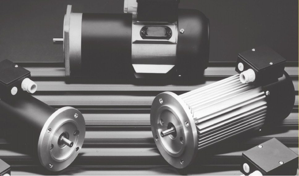
CARATTERISTICHE TECNICHE
Tutte le caratteristiche tecniche del
motore sono indicate nella targhet-
ta applicata sul corpo del motore,
per il corretto utilizzo ed una buona
durata del motore attenersi a quan-
to specificato.
Tutti i dati tecnici, quando non spe-
cificato diversamente, si intendono
con tolleranza ±5 %.
I motori di tipo brushless (senza
spazzole) nascono per essere accop-
piati con specifici alimentatori elet-
tronici, non sono quindi utilizzabili
accoppiati con altri alimentatori di
marca o tipo diverso da quanto pre-
visto.
La Motor Power Company declina
ogni responsabilità nel caso di uso
improprio del motore al di fuori del-
le caratteristiche specificate.
ITALIANO

STOCCAGGIO
E’ opportuno controllare lo stato del
motore al suo arrivo per verificare
eventuali danni di trasporto. Se i
motori non vengono installati subi-
to, vanno conservati in ambiente
asciutto, pulito, privo di vibrazioni e
protetto contro le brusche variazio-
ni di temperatura che possono pro-
vocare condensa.
ACCOPPIAMENTO
Questa operazione è molto delicata
e va eseguita con la massima cura
da parte di personale qualificato per
assicurare un buon funzionamento
del motore. Durante questa opera-
zione tenere presente i seguenti
punti:
• utilizzare organi di trasmissione
equilibrati e con tolleranze mecca-
niche tali da garantire un buon ac-
coppiamento;
• non dare urti violenti all’albero;
• fissare saldamente il corpo del
motore tramite la flangia anteriore
o il piede;
• nel caso di montaggio diretto a
bagno d’olio utilizzare un paraolio
sull’albero e sigillare i fori dei tiranti.
I motori, salvo esecuzioni speciali,
non possono essere montati nei
seguenti ambienti:
• dove è richiesto l’utilizzo di appa-
recchiature antideflagranti;
• dove sono sottoposti alla presen-
za di acqua o polvere in quantità
superiore al grado di protezione del
motore;
• dove sono sottoposti a tempera-
ture inferiori o superiori alle tempe-
rature di normale funzionamento (0°
÷40°C);
• dove sono sottoposti ad un grado
di umidità ambientale superiore alle
condizioni di normale funzionamen-
to (85% in assenza di condensa).
I motori possono essere montati in
qualsiasi posizione prestando atten-
zione a quanto segue:
• rendere possibilmente visibile l’eti-
chetta;
• considerare che il motore in fun-
zione può avere superfici a tempe-
ratura elevata, prevedere le neces-
sarie protezioni per gli operatori che
possono venirne a contatto;
• evitare che il motore si trovi inve-
stito da flussi d’aria calda provenien-
ti da altre parti della macchina o a
contatto con parti calde della stes-
sa;
• per i motori con ventilazione oc-
corre prestare attenzione a lasciare
libera la parte posteriore in modo
che si possa avere il giusto afflus-
so d’aria.
ITALIANO

ALIMENTAZIONE
Il cablaggio elettrico del motore al-
l’apparecchio di alimentazione deve
essere eseguito esclusivamente da
personale qualificato, che deve pre-
stare attenzione ai seguenti punti:
• nel collegare il motore all’alimen-
tatore rispettare gli schemi elettrici
di collegamento allegati al motore;
• dimensionare il sistema di alimen-
tazione in modo che in nessuna fase
di funzionamento possa erogare una
corrente superiore a 5 volte la cor-
rente nominale;
• isolare o rendere inaccessibili le
parti di connessione non isolate (con-
tatti in morsettiera, terminali di cavi,
connettori, ecc..);
• utilizzare cavi di alimentazione ido-
nei al tipo di installazione e alla cor-
rente nominale del motore presente
in etichetta;
• prevedere una protezione da so-
vraccarico e cortocircuito in quanto
non presenti sul motore, salvo ese-
cuzioni speciali;
• proteggere l’alimentatore da pos-
sibili ritorni di tensione ai capi del
motore nel caso questo si fermi per
inerzia;
• se richiesto l’utilizzo di cavi scher-
mati, per il corretto attestamento del-
lo schermo / calza riferirsi allo sche-
ma di cablaggio allegato.
MANUTENZIONE
Per ogni intervento o sostituzione di
particolari rivolgersi esclusivamente
al servizio assistenza della Motor
Power Company, facendo riferimento
al modello del motore (indicato in
etichetta con dicitura “TYPE”) ed al
suo codice (dicitura P.N.).
Per motori con spazzole verificarne
l’usura ogni 500 ore di funzionamen-
to. Per compiere questa operazione
scollegare il motore dall’alimentato-
re ed aprire gli appositi cassetti por-
taspazzole, estrarre le spazzole e
soffiare aria compressa deumidifica-
ta all’interno con una pressione mas-
sima di 2 bar. Nel caso in cui la lun-
ghezza del carboncino risulti inferio-
re a quanto riportato in tabella, so-
stituire le spazzole con un nuovo set.
TIPO DI LUNGHEZZA
MOTORE MINIMA
PENTA 1 / ESA 2
S-M-L 6 mm
PENTA 5 / ESA 3
X-XS-S-SL-M-L 9 mm
PENTA 4
S-M-L 12 mm
PENTA 7 / ESA 6
S-F-M-L 11 mm
ESA 9
S-M 11 mm
L6mm
ITALIANO

ITALIANO
MOTORI CON FRENO
Tutti i freni (optional) montati sui
motori sono di stazionamento del
tipo a sicurezza intrinseca (senza
tensione il freno blocca il motore),
possono essere usati solamente per
bloccare il motore fermo, e non per
frenate dinamiche. I valori dell’ali-
mentazione sono indicati in etichet-
ta con la relativa tolleranza del valo-
re di tensione accettata, nel caso
che questa condizione non sia rispet-
tata si può avere un’apertura par-
ziale o la non apertura del freno. La
coppia frenante nominale del freno
indicata a catalogo è di tipo statico
e si riferisce a freni funzionanti a
secco, con le superfici d’attrito as-
solutamente prive di grasso o altre
sostanze. Il freno è da ritenersi com-
pletamente disinserito solamente
una volta trascorso il suo tempo di
apertura rispetto all’istante di ali-
CONFORMITA’
Tutti i motori sono progettati e pro-
dotti in conformità a quanto stabili-
to dalle direttive europee 89/336 e
73/23 con le successive modifiche
e sono idonei ad essere incorporati
in una macchina che verrà dichiara-
ta conforme alla direttiva 89/392 e
successive modifiche.
mentazione, pertanto il motore do-
vrà iniziare a erogare coppia esclu-
sivamente dopo tale tempo
.

CAUTION
equipment under voltage. All ac-
tions must be fulfilled only by skilled
personnel.
The motors and the equipment sup-
plying the motor are industrial instru-
ments subjected to high voltage.
During the working, these devices
are made up of dangerous compo-
nents, owing to the voltage and to
the rotatory motion. They can cause
very dangerous injuries to things or
people if the following instructions
are not observed or if the necessary
mechanical and electric protections
are removed, or in case of incorrect
use or service.
In case of motors containing sen-
sors, transducers or other electron-
ical parts incorporated, these parts
can be damaged by electrostatic dis-
charges (ESD) let in through the con-
nections. Avoid touching the connec-
tion points of the electronic parts, if
there’s no suitable protection
against electrostatic discharges
(grounding bracelets, suitable tools
etc...).
The content of this manual must be
available to all the personnel in
charge of the installation, mainte-
nance and use of the motor. This
information has to be included in the
manuals of the machine, in which
the motor is installed.
It is not possible to introduce with
this issue the instructions covering
all the constructive versions nor any
single mounting service or mainte-
nance case.
TECHNICAL SPECIFICATIONS
All the technical specifications of the
motor are shown on the data plate
labelled on to the motor casing: for
a correct use and long life of the mo-
tor, follow carefully what is stated
on.
All the technical data, if not differ-
ently stated, have to be intended
with a tolerance of ±5%.
The brushless-type motors are made
to be connected to specific electron-
ic power supplies. Therefore they
cannot be connected to power sup-
plies of make and type other than
foreseen.
Motor Power Company declines any
responsibility in case of improper
motor use or out of its settled fea-
tures.
STORAGE
It is convenient to check the motor
conditions at its arrival to survey
eventual damages due to the trans-
port.
ENGLISH

ENGLISH
• in case of direct oil bath mounting
use an oil seal on the shaft and seal
the holes of the tie rods.
The motors, except for the special
executions, can’t be mounted in the
following cases:
• wherever the use of anti-
deflagrating equipment is requested;
• wherever the motors must work in
presence of water or dust in larger
quantity than what allowed by the
motor protection class;
• wherever they are submitted to tem-
perature lower or higher than the nor-
mal working temperature (0°÷40°C);
• wherever the motors are submit-
ted to a dampness level higher than
the normal working conditions (85%
in lack of condensation).
The motors can be fitted in any
position by giving great care to the
following:
• make sure that the data plate is
visible;
• consider that the motor in opera-
tion can have high-temperature sur-
faces. Provide the necessary protec-
tions for the operators that can come
in contact with them;
• make sure that the motor is not
exposed to hot air currents coming
from other parts of the machine or
that it is in contact with hot surfaces
of the machine;
• for the self-ventilated models it is
necessary to pay particular attention
to the rear part of the motor in or-
der to ensure a proper air flow.
SUPPLYING
The electric wiring of the motor to
the supplying unit has to be accom-
plished only by skilled personnel who
has to take care of the following:
• when connecting the motor to the
power supply, observe the wiring dia-
grams attached to the motor;
If the motors are not immediately
fitted, they have to be stored in a
dry, clean, vibration free surround-
ing, which must be protected by tem-
perature variations that could cause
condensation.
CONNECTION
This operation is very delicate and
has to be fulfilled with utmost care
by skilled personnel to ensure a
good working of the motor.
During the operation observe the fol-
lowing recommendations:
• use transmission components and
mechanical tolerances that can se-
cure a proper coupling;
• do not bump the shaft;
• firmly fasten the body of the mo-
tor through the front flange or the
foot;

MOTOR MIN.
TYPE LENGTH
PENTA 1 / ESA 2
S-M-L 6 mm
PENTA 5 / ESA 3
X-XS-S-SL-M-L 9 mm
PENTA 4
S-M-L 12 mm
PENTA 7 / ESA 6
S-F-M-L 11 mm
ESA 9
S-M 11 mm
L6mm
MOTORS EQUIPPED WITH
BRAKE
All the brakes (optionals) fitted on
the motors are emergency brakes of
the intrinsic safety type (in absence
of voltage the brake stops the mo-
tor): they can be used only for jam-
MAINTENANCE
For any operation or component re-
placing, apply exclusively to the
maintenance service of Motor Power
Company, making reference to the
model of the motor (stated on the
data plate as “TYPE”) and to its part
number (P.N.).
As to motors with brushes, it is nec-
essary to check the wear of the
brushes every 500 hours of opera-
tion.
For executing this operation discon-
nect the motor from the power sup-
ply, open the brush holder, extract
the brushes and blow dehumidified
compressed air at max. 2 bar pres-
sure: if the brush is shorter than
what stated in the chart, arrange for
replacing the complete set with a
new one.
• The feeder should be limited to
supply current up to 5 times higher
than the rated current at every work-
ing stage;
•isolate or make inaccessible all
the connecting parts which are not
isolated (terminal box connections,
cable terminals, connectors, etc. );
• use power cables suitable for the
type of installation and the motor
rated current shown in the label;
•provide for a protection against
overload and short circuit, since they
are not supplied with the motor, ex-
cept in case of special executions;
•protect the power supply by even-
tual voltage feedback on the end
parts of the motors, in case it stops
owing to the inertia;
• if screened cables are requested
for the correct positioning of the
plait, refer to wiring diagram en-
closed.
ENGLISH

ENGLISH
ming the still motor, not for dynamic
braking.
The supplying voltage is shown on
the data plate with its tolerance:
should this condition not be re-
spected, there might be a partial
opening or no opening at all of the
brake.
The rated braking torque of the brake
shown on the catalogue is a static
one and refers to brakes working in
dry conditions with the friction sur-
faces absolutely without grease or
other substances.
The brake could be entirely discon-
nected only once the time necessary
for its opening has elapsed since the
moment of feeding. Therefore the
motor will have to supply torque only
after this period of time.
CONFORMITY
All the motors are designed and
manufactured according to European
directives 89/336 and 73/23 and
following modifications. They are
suitable to be included in a machine,
which will be declared in accordance
with directive 89/392 and following
modification

ACHTUNG
Die Geräte stehen unter Spannung!
Alle Vorgänge dürfen nur von ange-
lerntem Personal durchgeführt wer-
den! Sowohl bei den Motoren als
auch bei der Leistungsversorgung
der Motoren handelt es sich um in-
dustrielle Geräte, die unter hoher
Spannung stehen können. Die durch
die Rotationsbewegung entstehende
Spannung macht die Einzelkompo-
nenten während des Betriebs sehr
gefährlich. Sie können bei Nichtbe-
achtung der folgenden Hinweise, bei
Entfernung der notwendigen mecha-
nischen oder elektrischen Schutz-
maßnahmen oder bei nicht korrek-
tem Gebrauch oder Service zu
schweren Sach- oder Personenscha-
den führen.
Bei Motoren, welche Sensoren,
Transduktoren oder andere elektro-
nische eingebaute Teile enthalten,
können diese Teile von elektrostati-
schen Entladungen (ESD), welche
durch die Anschlüsse eingeleitet
werden, beschädigt werden. Es ist
zu vermeiden, die Anschlusspunkte
der elektronischen Teile zu berühren,
wenn man keine geeignete Schutz-
vorrichtungen gegen elektrostati-
sche Entladungen zur Verfügung hat
(Armbänder zur Erdung, geeignete
Werkzeuge usw...).
Der Inhalt dieses Handbuchs muß
für das Personal, das mit der Instal-
lation, Wartung und Benutzung des
Motors beauftragt ist, verfügbar
sein. Deshalb muß man diese Aus-
künfte in den entsprechenden Hand-
büchern der Maschine, an welcher
der Motor angebracht wird, einfügen.
Bitte beachten Sie, daß Motor Po-
wer Company mit dieser Ausgabe
des Handbuches nicht alle Hinwei-
se für die verschiedenen Bauversio-
nen oder für einzelne Einbaubedin-
gungen oder Instandhaltungsfälle ab-
decken kann.
TECHNISCHE SPEZIFIKATIO-
NEN
Alle technischen Daten des Motors
sind auf dem Datenschild am Motor-
körper aufgeführt. Für den korrekten
Gebrauch und eine lange Lebensdau-
er des Motors den Angaben bitte
sorgfältig folgen! Alle Technischen
Daten sind, wenn nicht anders gege-
ben, mit einer Toleranz von +/- 5 %
zu betrachten.
Die Motoren Typ Brushless (ohne
Bürsten) werden hergestellt, um mit
besonderen elektronischen Strom-
versorgungsgeräten verbunden zu
werden. Sie können also mit Strom-
versorgungsgeräten von einer Mar-
ke oder Art, die anders als vorgese-
hen ist, nicht benutzt werden.
Nicht bestimmungsgemäßer Ge-
brauch führt zum Ausschluß jeglicher
Haftung und Gewährleistung von
Motor Power Company.
DEUTSCH

DEUTSCH
LAGERUNG
Der Zustand des Motors sollte bei
Eintreffen der Lieferung überprüft
werden, um eventuelle Transport-
schäden festzustellen. Sollten die
Motoren nicht sofort eingebaut wer-
den, muß die Lagerung in einer
trockenen, sauberen und erschütte-
rungsfreien Umgebung erfolgen, die
gegen Temperaturschwankungen
geschützt sein muß, da diese Kon-
densation verursachen kann.
ANSCHLUSS
Für einen einwandfreien Betrieb des
Motors ist es wichtig, daß die Inbe-
triebnahme mit größter Sorgfalt und
nur von angelerntem Personal er-
folgt!
Während des Betriebs bitte folgen-
de Empfehlungen beachten:
•Antriebskomponenten und mecha-
nische Toleranzen verwenden, die
eine sichere Kopplung ermöglichen;
•nicht auf die Welle schlagen;
•den Motorkörper fest über den
Frontflansch oder den Fuß verbin-
den;
•bei direktem Einbau in einer Öl-
wanne für die Welle ein Ölsiegel ver-
wenden und die Löcher der Spurst-
angen versiegeln.
Außer in Spezialanwendungen kön-
nen die Motoren unter folgenden
Bedingungen nicht eingebaut wer-
den:
•unter Verwendung eines “Anti-de-
flagrating equipmemt”;
•wenn der Motor unter Staub- und
Wasserbedingungen betrieben wird,
die nicht mehr in die angegebenen
Schutzklassen fallen;
•wenn der Motor geringeren oder
höheren Temperaturen ausgesetzt
wird als der normalen Betriebstem-
peratur (0°÷40°C);
•wenn der Motor einer höheren
Luftfeuchtigkeit ausgesetzt wird als
unter normalen Betriebsbedingun-
gen (85% ohne Kondensation).
Die Motoren können - unter sorgfäl-
tiger Berücksichtigung folgender
Punkte - in jeder Lage eingebaut
werden:
•stellen Sie sicher, daß das Daten-
etikett lesbar ist;
• man muß in Betracht ziehen, daß
der laufende Motor heiße Oberflä-
chen haben kann. Die notwendigen
Schutzvorrichtungen für die Bedie-
ner, die damit in Berührung kommen
können, müssen vorhanden sein;
•stellen Sie sicher, daß der Motor
keinen heißen Luftströmen ausge-
setzt ist, die aus anderen Teilen der
Maschine kommen und daß der
Motor nicht mit heißen Oberflächen
der Maschine in Berührung kommt;
•bei den Motoren mit eigener Ven-
tilation muß besonders darauf ge-

achtet werden, daß auf der Rücksei-
te des Motors die Luftzirkulation
gewährleistet ist.
VERSORGUNG
Der elektrische Anschluß zwischen
Motor und Versorgungsgerät darf nur
von ausgebildetem Personal unter
Berücksichtigung folgender Punkte
durchgeführt werden:
• bei der Verbindung des Motors mit
dem Stromversorgungsgerät sind die
dem Motor beigefügten Schaltpläne
zu beachten;
• der Speiseapparat muß geeignet
sein, so daß die Drehmomentsver-
sorgung nicht größer als fünf Mal
das Nenndrehmoment ist;
•alle nicht isolierten Verbindungs-
elemente (Klemmverbinder, Stecker,
usw...) müssen isoliert oder uner-
reichbar gemacht werden;
• Versorgungskabel benutzen, die
für die Installation und den Motor-
nennstrom (am Etikett vorhanden)
geeignet sind;
•sorgen Sie für einen Schutz ge-
gen Überlast und Kurzschluß - dies
ist beim Motor nicht vorgesehen,
außer es handelt sich um eine spe-
zielle Ausführung;
•für den Fall, daß der Motor auf-
grund von Trägheit zum Stillstand
kommt, muß Leistungsversorgung
an den Enden des Motors gegen
Spannungsrückführungen geschützt
werden.
• werden Abschirmkabel für die kor-
rekte Positionierung der Beflechtung
erfordert, sich auf beiliegendes Ver-
drahtungsschema beziehen.
INSTANDHALTUNG
Für jeden Vorgang oder Austausch
von Komponenten wenden Sie sich
bitte ausschließlich an der Service
von Motor Power Company. Nehmen
Sie dabei bitte Bezug auf das Mo-
tormodell (als “TYPE” auf dem Da-
tenschild aufgeführt) und auf die Se-
riennummer (P.N.).
Bei Motoren mit Bürsten ist der Ver-
schleiß der selben alle 500 Betriebs-
stunden zu prüfen.
Dafür muß der Motor zunächst von
der Leistungsversorgung getrennt
werden und der Bürstenhalter geöff-
net werden. Dann müssen die Bür-
sten ausgezogen werden und mit
max. 2 Bar Preßluft geblasen wer-
den: ist die Bürste kürzer als in der
Tabelle angegeben, sollte das Set
vollständig durch neue Bürsten er-
setzt werden.
DEUTSCH

DEUTSCH
KONFORMITÄT
Alle Motoren werden in Übereinstim-
mung mit den europäischen Richtli-
nien 89/336 und 73/23 und folgen-
den Änderungen entwickelt und her-
gestellt. Sie sind geeignet dafür, in
eine Maschine eingebaut zu werden,
welche für übereinstimmend mit der
Richtlinie 89/392 und folgende Än-
derungen erklärt wird.
MOTOR MINDESTLANGE
TYP
PENTA 1 / ESA 2
S-M-L 6 mm
PENTA 5 / ESA 3
X-XS-S-SL-M-L 9 mm
PENTA 4
S-M-L 12 mm
PENTA 7 / ESA 6
S-F-M-L 11 mm
ESA 9
S-M 11 mm
L6mm
MOTOREN MIT BREMSE
Alle an den Motoren angebauten (op-
tionalen) Bremsen sind Notbremsen
des intrinsischen Sicherheitstyps
(ohne Spannung stoppt die Bremse
den Motor): die Bremsen können nur
den Motor im Stillstand halten, nicht
aber dynamisch bremsen.
Der Versorgungswert ist auf dem
Datenschild mit Toleranz aufgeführt:
wird diese Bedingung nicht berück-
sichtigt, kann es sein, daß die Brem-
se teilweise oder gar nicht öffnet.
Das im Katalog genannte Nenndreh-
moment der Bremse ist statisch und
bezieht sich auf Bremsen, die in
trockener Umgebung betrieben wer-
den und deren Reibungsoberflächen
absolut ohne Schmiere oder andere
Substanzen beeinträchtigt sind.
Die Bremse ist völlig abschalten, nur
nach seinen Öffnungszeit in Bezug
auf das Speisungsmoment; die Dreh-
momentsversorgung kann nur nach
dieser Zeit geschehen.

ATTENTION
Appareillage sous tension, toutes
les opérations doivent être faites,
exclusivement, par personnel qua-
lifié.
Les moteurs et les appareils qui les
alimentent sont des instruments in-
dustriels soumis à une haute ten-
sion. Pendant le fonctionnement ces
dispositifs présentent des parties
dangereuses, parce qu’elles sont
mises sous tension et en rotation.
Ils peuvent provoquer des graves
dommages ou choses aux person-
nes, si on ne respecte pas les ins-
tructions suivantes, si on enleve les
protections électriques et mécani-
ques nécessaires, et si l’utilisation
n’est pas appropriée ou le service
n’est pas correct.
Les capteurs, transducteurs ou des
autres parties électroniques, qui
peuvent être incorporées dans les
moteurs, pourraient être endomma-
gés par des décharges électrostati-
ques (DES) introduites par les bran-
chements. Eviter donc de toucher les
points de connexion des parties
électroniques sans avoir des protec-
tions adéquates contre les déchar-
ges électrostatiques (bracelets de
connexion de mise à la terre, outils
conçus à cet effet etc...).
Le contenu de ce manuel doit être
disponible pour tout le personnel
chargé de l’installation, la manuten-
tion et l’utilisation du moteur. Il est
donc nécessaire que sur les ma-
nuels de la machine soient décrites
les informations sur le moteur ins-
tallé. Les instructions contenues
dans ce manuel ne peuvent pas,
pour des raisons de clarté, contenir
dans le détail toutes les infomations
concernant tous les types de cons-
truction possible, ni chaques possi-
bilité de montage, de service ou de
manutention.
CARACTERISTIQUES TECHNI-
QUES
Toutes les caractéristiques techni-
ques du moteur sont indiquées sur
l’étiquette apposée sur le corps du
moteur; pour une utilisation correc-
te et durable du moteur on doit se
conformer aux valeurs indiqués. Tou-
tes les informations techniques sont
données avec une tolérance de ±5%
(sauf indication contraire). Les mo-
teurs de type brushless (sans balais)
sont conçus pour être couplés avec
alimentateurs électroniques spécifi-
ques. Ils ne peuvent pas être cou-
plés avec des autres alimentateurs
de marque ou type différents.
Motor Power Company décline tou-
tes responsabilités en cas d’utilisa-
tion du moteur au delà des caracté-
ristiques données.
FRANCAIS

FRANCAIS
STOCKAGE
Il est nécessaire de contrôler l’état
du moteur à sa livraison afin de dé-
tecter d’éventuels dommages liés au
transport. Si les moteurs ne sont
pas installés immédiatement, il faut
les conserver dans un lieu sec, pro-
pre, sans vibration et protégé des
variations de températures qui peu-
vent provoquer de la condensation.
MONTAGE
Cette opération est très délicate et
le personnel qualifié doit l’exécuter
avec beaucoup de soins pour assu-
rer un fonctionnement correct du
moteur. Pendant cette opération on
doit veiller aux points suivants:
•utiliser des organes de transmis-
sion équilibrés et ayant des toléran-
ces mécaniques garantissant un
accouplement correct;
•ne pas donner de coups violents
sur l’arbre;
•fixer solidement le corps du mo-
teur par sa bride ou sa patte de fixa-
tion;
•en cas de montage direct à bain
d’huile, utiliser un joint sur l’arbre
et boucher les trous des tirants.
Les moteurs, sauf exécutions spé-
ciales, ne peuvent pas être montés
dans les lieux suivants:
•où il est demandé l’utilisation
d’appareils antidéflagrants;
•où ils sont soumis à la présence
d’eau ou de poussière en quantité
supérieure au degré de protection
du moteur;
•où ils sont soumis à des tempé-
ratures inférieures ou supérieur à
celles du fonctionnement normal
(0°÷40°C);
•où ils sont soumis à un degré
d’humidité ambiant supérieur aux
conditions de fonctionnement nor-
mal (85% sans condensation).
Les moteurs peuvent être montés
dans toutes les positions en respec-
tant les indications suivantes:
•mettre, si possible, l’étiquette vi-
sible;
• considérer que le moteur en fonc-
tion peut avoir des surfaces avec
des températures élevées. Il faut
prévoir des protections nécessaires
pour les opérateurs qui en peuvent
entrer en contact;
•eviter que le moteur se trouve
dans un flux d’air chaud, provenant
d’autre parties de la machine, ou au
contact de ces parties chaudes;
•pour les moteurs avec ventilation,
veiller à laisser libre la partie posté-
rieure du moteur pour avoir un af-
flux d’air correct.

ALIMENTATION
Le câblage électrique du moteur à
l’appareil d’alimentation doit être
réalisé par le personnel qualifié, qui
doit respecter les points suivants:
• coupler le moteur à l’alimentateur
en observant les schémas de con-
nexion qui sont inclus avec le mo-
teur;
•adapter l’alimentateur de sorte
que il ne puisse pas founir courant
supérieure 5 fois au courant nomi-
nal pendant n’importe quelle phase
de fonctionnement;
•isoler ou rendre inaccessibles les
parties de connections non isolées
(contacts dans la boite à bornes,
boîtes d’extrémité des câbles, con-
necteurs etc...);
• utiliser des câbles d’alimentation
conçus au type d’installation et au
courant nominal du moteur décrits
sur l’étiquette;
•prévoir une protection de surchar-
ge et court circuit qui n’existe pas
sur le moteur, sauf exécution spé-
ciale;
•protéger la platine d’alimentation
contre le retour de tension fourni par
le moteur lorsqu’il est générateur;
• s’il est requit l’utilisation de câ-
bles blindés se référer au schéma
de câblage ci-joint pour le correct
positionnement de la tresse de blin-
dage.
MANUTENTION
Pour chaque opération ou remplace-
ment de pièces, il faut contacter
exclusivement le service d’assistan-
ce de Motor Power Company en in-
diquant le modèle du moteur (indi-
qué sur l’étiquette “TYPE”) et le code
(P.N.). On doit vérifier l’usure des
moteurs avec balais tous les 500
heures de fonctionnement.
FRANCAIS
Pour effectuer cette opération, il faut
déconnecter le moteur de son ali-
mentation, ouvrir les caches porte-
balais, extraire les balais et souffler
d’air comprimée et deshumidifiée
son intèrieure avec une pression
maximale de 2 bar.
Si la longueur des balais est infé-
rieure aux valeurs indiquées dans le
tableau, il faut remplacer les balais.
TYPE DE LONGUEUR
MOTEUR MINIMUM
PENTA 1 / ESA 2
S-M-L 6 mm
PENTA 5 / ESA 3
X-XS-S-SL-M-L 9 mm
PENTA 4
S-M-L 12 mm
PENTA 7 / ESA 6
S-F-M-L 11 mm
ESA 9
S-M 11 mm
L6mm

FRANCAIS
MOTEUR AVEC FREIN
Toutes les freins (en option) mon-
tés sur nos moteurs sont de station-
nement du type à sureté intrisèque
(sans tension le frein bloque le mo-
teur).
Ils ne doivent être utilisés que pour
maintenir le moteur à l’arrêt et pas
en freinage dynamique.
Les valeurs d’alimentation sont in-
diquées sur l’étiquette avec leur to-
lérance, si cette condition n’était pas
respectée on pourrait avoir aucune
ouverture ou partielle du frein.
Le couple de freinage nominal indi-
qué dans le catalogue est de type
statique et correspond aux freins qui
fonctionnent à sec, avec les surfa-
ces de friction absolument sans gras
ou sans autres substances.
Le frein est débraché seulement
quand son instant d’ouverture est
passé par rapport à l’instant d‘ali-
CONFORMITE
Tous les moteurs sont conçus et
produits en conformité avec les di-
rectives européennes 89/336 et
73/23 et modifications suc-
cessives. Ils sont indiqués pour être
incorporés dans une machine qui
sera déclarée conforme à la direc-
tive 89/392 et modifications suc-
cessives.
mentation; par conséquent le mo-
teur peut founir couple exclusive-
ment aprés cet instant.

CABLAGGIO CON PRESSACAVO
• Spelare i singoli fili (quota * nel
disegno) di una lunghezza di 10 mm
per cavo segnale e di 7 mm per cavi
di potenza inserendo appositi pun-
talini
• Rivoltare la schermatura sul parti-
colare 1 e bloccarla inserendo il
particolare 2, accertandosi che la
calza sia a contatto con tutta la su-
perficie del particolare 2
• Avvitare il coperchio del pressaca-
vo al particolare 2
WIRING WITH CABLE GLAND
• Strip single wires (section * in the
drawing) of 10 mm length for signal
cable and 7 mm length for power ca-
ble by placing suitable pin terminals
• Overturn the shielding on detail 1
and lock it by introducing the detail
2, making sure the braiding is in
contact with the entire surface of
detail 2
• Screw the cable gland cover to
detail 2
VERDRAHTUNG MIT
STOPFBÜCHSENBRILLE
• Die einzelnen Drähte (Abschnitt *
auf Zeichnung) für eine Länge von
10 mm beim Signalkabel und von 7
mm bei Leistungskabeln abisolieren.
Die eigens dazu bestimmten Kabel-
schuhe einsetzen
• Die Abschirmung auf Teil 1 umdre-
hen und sie durch das Einsetzen von
Teil 2 festmachen. Sich vergewis-
sern, daß das Geflecht in Kontakt
mit der ganzen Oberfläche von Teil
2 ist
• Den Deckel der Stopfbüchsenbri-
le an das Teil 2 anschrauben
CÂBLAGE AVEC
PRESSE-ÉTOUPE
• Dégainer tous les fils (section*
dans le dessin) de longueur 10 mm
pour le câble signal et longueur 7
mm pour les câbles puissance en y
introduisant des pins.
• Renverser le blindage sur le détail
1 et le bloquer en introduisant le
détail 2, et s’assurer que la tresse
est à contact avec toute la surface
du détail 2
• Visser le couvercle du presse-étou-
pe au détail 2
This manual suits for next models
31
Table of contents
Languages:
Other Motor Power Company Engine manuals