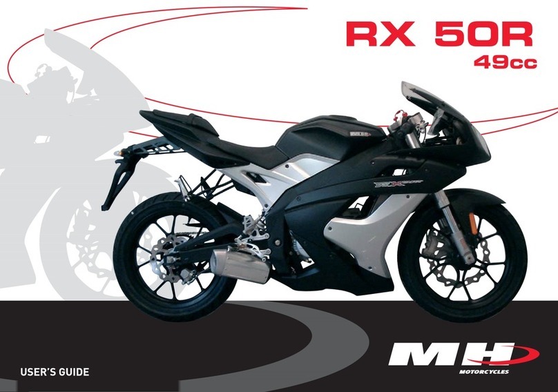
Motorhispania MH7 Naked Instruction manual


3
IMPORTANT
WARNING
CONTAINS A POTENTIAL DANGER THAT MAY CAU-
SE INJURY OR EVEN DEATH.
CAUTION
WARNING OF POSSIBLE DAMAGE TO THE MACHINE.
N.B.
CONTAINS SPECIAL INFORMATION TO AID MAINTE-
NANCE OR CLARIFY SOME POINT IN THE INSTRUC-
TIONS.
THIS SERVICE MANUAL HAS BEEN PREPARED FOR
AUTHORISED DEALERS OF G. H E MOTORHISPANIA,
S.L. AND SHOULD ONLY BE USED BY QUALIFIED
TECHNICAL SERVICE DEPARTMENT MECHANICS.
INEXPERIENCED MECHANICS OR THOSE WITHOUT
THE APPROPRIATE TOOLS AND EQUIPMENT CAN-
NOT CARRY OUT THE SERVICE WORK DESCRIBED
IN THIS MANUAL CORRECTLY.
A POOR REPAIR MAY CAUSE INJURY TO THE ME-
CHANIC, AND THE MACHINE MAY NOT BE IN CON-
DITION TO GUARANTEE THE SAFETY OF THE RIDER
AND PILLION PASSENGERS.
READ THIS MANUAL AND FOLLOW THE INSTRUCTIONS CAREFULLY. THE ESPECIALLY IMPORTANT
INFORMATION HAS BEEN INDICATED WITH THE WORDS WARNING, CAUTION AND N.B.,
WHICH HAVE VERY PRECISE MEANINGS.
•

4
FOREWORD
This manual describes the procedures for the diagnosis, maintenance, adjustments, basic service work, chan-
ging of parts and the dismantling and assembly of the main parts.
Model applicable:
MH7 NAKED with the following and subsequent VIN numbers:
VTVNK01E307XXXXXX ~
This text is classified into sections, each of which has a section number, as can be seen in the Contents on the
following page, and on the first page of every individual section there is a contents list for that section.
Keep this manual to hand so that it can be consulted quickly when carrying out service work.
The specified points must be carefully observed to ensure that the machine functions perfectly in accordance
with the specification.
When changing parts or carrying out service work that involves dismantling, it is recommended to use genuine
G.H.E. MOTORHISPANIA, S.L. spare parts, tools and service materials as specified in the corresponding des-
criptions
All the information, figures and specifications in this manual are based on the latest approved product informa-
tion available at the time of publication.
The main model used for the description throughout this manual is the model with basic specifications.
The figures may therefore appear slightly different from the model in the workshop. G.H.E. MOTORHISPANIA,
S.L. reserves the right to make changes without prior warning.
G.H.E. MOTORHISPANIA. S.L.
SERVICE DEPARTMENT
© Copyright G.H.E. MOTORHISPANIA. S.L. 2007

9
IDENTIFICATION
CHASSIS IDENTIFICATION NUMBER
The chassis identification number is located at the front right-hand
side of the machine.
The chassis number is required when requesting any motorcycle
part.
ENGINE IDENTIFICATION NUMBER
The engine identification number is located at the top right-hand
side of the engine.
The engine number is required when requesting any engine part.
1GENERAL INFORMATION

13
GENERAL SPECIFICATIONS
ELEMENT SPECIFICATIONS
MODEL CODE MH7 NAKED 125cc
DIMENSIONS
Total length:
Total width
Height without rear-view mirrors
Distance between axles
WEIGHT
1980 mm
750 mm
795 mm
1310 mm
120 kg
2
SPECIFICATIONS
2

14
2SPECIFICATIONS
CHASSIS SPECIFICATIONS
ELEMENT SPECIFICATIONS
WHEELS
Front wheel
Front tyre
Front pressure
Rear wheel
Rear tyre
Rear pressure
FRONT BRAKE
Type
ø brake pistons
ø of disk
Thickness of disk
ø main piston (cylinder)
REAR BRAKE
Type
ø brake pistons
ø of disk
Thickness of disk
ø main piston (cylinder)
FRONT SUSPENSION
Type of suspension:
Type of front forks
Forks capacity
Travel
REAR SUSPENSION
Type of suspension
Central hydraulic single shock absorber travel
STEERING
Tipo
2,75 x 17”
Continental 100/ 80 - 17
1,5 bar
3 x 17”
Continental 130/70 - 17
2 bar
Hydraulic disk, radial calliper
25 mm
Ø 300mm
4±1
Ø 11mm
Hydraulic disk
Ø 25mm
Ø 220mm
4±1 mm
Ø 12mm
Hydraulic telescopic forks
41 mm inverted; advanced shaft
360±4 cc
90 mm
Swinging arm with single central shock absorber
45±2 mm
Column mounted on ball bearings

15
ENGINE SPECIFICATIONS
ELEMENT SPECIFICATIONS
ENGINE
Type of engine
Make
Cubic capacity
Diameter x stroke
Maximum power
Maximum torque ratio
FUEL
Recommended fuel
Total capacity of fuel tank
(including reserve)
LUBRICACIÓN
Recommended oil
Oil tank capacity
COOLING
Type
IGNITION
Type
Spark plug
CARBURETTOR
Type
Main jet
Idling jet
Needle / Position
Float height
Air screw position
TRANSMISSION
Type
Primary transmission
Secondary transmission
Gearbox
Gearbox capacity
Clutch
MAGNETO
STARTER MOTOR
Single cylinder 4-stroke
YAMAHA
123,7 cc
54 mm X 54 mm
7,5 Kw a 9000 min-1
9,4 Nm a 6500 min-1
95 or 98 octane lead free petrol
12.5 litres
10W30
1 Litre
Air
Electric
NGK; CR6HSA
MIKUNI 3D6/10
#95
#15
5QGJ3 / 2
18,9 mm
1 1/2 turns
Primary by gears
Final by chain
Gears; 68 x 20
Chain; 52 x 14
5 speed
1,2
Multidisk- multidisks bathed in oil with manual control.
MORIC; 3D9
Electric/Kick-start lever
SPECIFICATIONS
2

16
TIGHTENING TORQUES
ITEM TIGHTENING TORQUE
BODYWORK
Side covers
Front mudguards
Rear mudguards
Skirting
CHASSIS
Front wheel shaft
Front wheel shaft clamp
Rear wheel shaft nut
Suspension arm nut
Engine chassis mounting
Shock absorber top mounting
Shock-absorber base mount
Forks T-sections
Front brake calliper
Rear brake calliper
Front brake disk
Rear brake disk
Support on chassis
Steering lock
STANDARD
5 mm diameter bolt and nut
6 mm diameter bolt and nut
8 mm diameter bolt and nut
10 mm diameter bolt and nut
12 mm diameter bolt and nut
0,1 daN·m (1 N·m)
0,1 daN·m (1 N·m)
0,8/0,1 daN·m (8/1 N·m)
4,5 daN·m (45 N·m)
1,2 daN·m (12 N·m)
6,5 daN·m (65 N·m)
6,5 daN·m (65 N·m)
2,8 daN·m (28 N·m)
4,3 daN·m (43 N·m)
4,3 daN·m (43 N·m)
1,5 daN·m (15 N·m)
2,5 daN·m (25 N·m)
2,5 daN·m (25 N·m)
1 daN·m (10 N·m)
1 daN·m (10 N·m)
1,9 daN·m (19 N·m)
0,6 daN·m (6 N·m)
0,5 daN·m (5 N·m)
1 daN·m (10 N·m)
2,2 daN·m (22 N·m)
3,5 daN·m (35 N·m)
5,5 daN·m (55 N·m)
2SPECIFICATIONS

19
COMMISSIONING
PREPARING THE BATTERY
(EXCEPT MAINTENANCE-FREE BATTERIES)
Regarding use of electrolyte, please read this manual carefully and fill the electrolyte liquid correctly, making sure
not to spill any.
WARNING:
Check to make sure the electrolyte is the same type as in the battery.
The electrolyte must always be filled with the battery removed from the machine.
The fitting of bolts and nuts must be carried out after filling with electrolyte.
PREPARING THE BATTERY:
Place the battery on a flat surface and remove the filling orifice seal.
PREPARING THE ELECTROLYTE:
Remove the electrolyte container from the PVC wrapping and remove the top cover by sliding sideways.
FILLING THE BATTERY WITH ELECTROLYTE:
Fit the electrolyte container vertically into the battery filling orifice and push in with a single movement. This will
cause the seal to break and allow the liquid filling to begin.
N.B.: The electrolyte container needs to be correctly inserted, otherwise the battery may fall over or the sul-
phuric acid may spill out
PLEASE CHECK THE FOLLOWING:
That bubbles are emerging from the 6 reservoirs.
That the liquid level is falling gradually.
Allow to stand for 10 minutes (no more than 12 hours)
N.B.: If there are places where no bubbles are emerging, the liquid can be encouraged to enter by tapping this
part with the finger without removing the electrolyte container.
REMOVING THE ELECTROLYTE CONTAINER:
Check once again that no electrolyte is remaining. If there is electrolyte remaining, tap the container gently.
Remove the electrolyte container carefully.
Clean off any electrolyte that may have splashed onto the battery.
FITTING THE HERMETIC PLUG:
Remove the hermetic plug fitted to the battery and position it gently horizontally lined up with the liquid filling
orifice.
Push down several times with both hands on the 6 parts until it is at the same level as the top of the battery.
N.B.: Do not adopt the method of pushing each hermetic plug once.
PRECAUTIONS FOR HANDLING:
Take care that the electrolyte does not come into contact with the skin or eyes when filling the battery.
In the event of electrolyte coming into contact with clothing or skin, the affected part must be washed immedia-
tely with plenty of water and then washed with soap and water.
In the event of electrolyte coming into contact with the eyes, the effected eye must be washed immediately with
running water and the nearest medical personnel contacted.
Before disposing of the container, it should be made safe by diluting the contents in water or neutralising it and
then washing the contents with water.
Sulphuric acid: 41%
Specific weight: 1.32
3
3

20
WARNING
NEXT, THE BATTERY LEVEL MAY NEED TO BE ESTA-
BLISHED AFTER A COMPLETE CHARGE, USING EX-
CLUSIVELY DISTILLED WATER.
COMMISSIONING THE FUEL AND OIL
CIRCUITS
1) Start up the engine and check that it is running correctly.
2) Fill the tank up with 95 or 98 octane lead-free petrol
CHECKS BEFORE DELIVERY TO CUSTOMER
1) Check the tightness of the wheel nuts.
Front wheel shaft nut tightening torque:
1,2 daN.m (12 N.m)
Rear wheel shaft nut tightening torque:
6,5 daN.m (65 N.m)
2) Check tightness of nuts and bolts (see Tightening torques).
3) Check the adjustment and effectiveness of the brakes.
4) Check the inflation pressure of the tyres when cold.
Front tyre inflation pressure:
1,5 bars
Rear tyre inflation pressure:
2 bars
5) Check that the lights, the turn indicators, the horn and
the brake light are functioning correctly.
6) Check the functioning of the different indicator lights.
7) Carry out a road test.
3COMMISSIONING
CHECKING LEVELS
1) Check the gearbox oil level.
2) Check the coolant level.
3) Check the brake fluid level.

21
CONTENTS
FRONT COVERS
CENTRAL COVERS
SEAT
PILLION PASSENGER SEAT
REAR COWLING
GRILL
NUMBER PLATE
FUEL CAP
TANK COVERS
FUEL TANK
BATTERY SUPPORT
FRONT MUDGUARDS.
FRONT FOOTRESTS
REAR FOOTRESTS
CHAIN
CHAIN PROTECTOR
GEAR CHANGE PEDAL
FRONT WHEEL
FRONT BRAKE CALLIPER
FRONT BRAKE DISK
REAR WHEEL
REAR BRAKE CALLIPER
REAR BRAKE DISK
REAR BRAKE FLUID RESERVOIR
REAR BRAKE LEVER
REAR SPROCKET
PROP-STAND
FRONT BRAKE LEVER
FRONT BRAKE FLUID RESERVOIR
THROTTLE CONTROL
CLUTCH LEVER
COMMUTATOR
HANDLEBARS
INSTRUMENT PANEL
IGNITION SWITCH
EXHAUST PIPE
AIR FILTER
SHOCK ABSORBER
SWINGING ARM
FORKS
CARBURETTOR
23
23
24
25
25
26
26
27
28
29
30
30
31
31
32
33
33
34
35
35
36
38
38
39
39
40
40
41
41
42
42
43
43
44
44
45
46
46
47
48
50
4CHASSIS

23
FRONT COVERS
REMOVAL
• Unscrew the 3 Allen bolts (A) on each end of the cover.
• Remove the front cover
ASSEMBLY
• To assemble, carry out the operations in reverse or-
der.
CENTRAL COVERS
REMOVAL
• Remove the seat (see section).
• Unscrew the 3 Allen bolts (A) on each end of the cover.
• Remove the central cover.
ASSEMBLY
• To assemble, carry out the operations in reverse order.
A
A
CAUTION
WHEN YOU REMOVE THE COVERS, LEAVE THEM
FACING UPWARDS TO AVOID DAMAGING THE PAINTWORK
Allen key
A
A
Allen key
4CHASSIS

24
SEAT
REMOVAL
• Insert the key in the lock and turn 90º to the left.
• Pull the seat upwards and backwards.
ASSEMBLY
• Fit the central tab (A) under the flange (B).
• At the same time, fit the two anchorages (C), located on
both sides of the seat, onto the chassis securing flanges.
• Lower the back of the seat.
• Turn the key 90º to the right and remove it.
A
C
B
4CHASSIS

25
Allen key
REAR COWLING
REMOVAL
• Remove the seat (see section).
• Remove the pillion passenger seat (see section).
• Unscrew the 4 Allen bolts (A).
• Remove the cowling.
ASSEMBLY
• To assemble, carry out the operations in reverse order.
A
A
A
PILLION PASSENGER SEAT
REMOVAL
• Remove the seat (see section).
• Unscrew the 4 Allen bolts (A).
• Remove the pillion passenger seat.
ASSEMBLY
• Fit the pillion passenger seat in its position.
• Screw on the 4 Allen bolts and 4 washers.
• Fit the seat (see section).
A
A
Allen key
CAUTION
WHEN YOU REMOVE THE COVERS, LEAVE THEM
FACING UPWARDS TO AVOID DAMAGING THE
PAINTWORK.
4CHASSIS

26
GRILL
REMOVAL
• Remove the front covers (see section).
• Remove the grill, by pulling upwards.
ASSEMBLY
• To assemble, carry out the operations in reverse order.
NUMBER PLATE
REMOVAL
• Remove the seat (see section).
• Remove the pillion passenger seat (see section).
• Remove the right and left-hand rear cowling (see section).
• Remove the turn indicators (see section).
• Remove the rear light (see section).
• Unscrew the 3 Allen bolts (A).
• Remove the number plate.
ASSEMBLY
• To assemble, carry out the operations in reverse order.
A
4CHASSIS
Allen key

27
Allen key FUEL CAP
REMOVAL
• Remove the cap (A).
• Unscrew the 5 Allen bolts (B).
• Remove the support orifice(C).
• Unscrew the 3 screws (D) from the cover.
• Remove the top tank cover (E).
• Remove the joining seal (F).
• Unscrew the 6 Allen bolts (G).
• Remove the tank filler hole.
• Remove the tank filler hole rubber seal.
ASSEMBLY
• To assemble, carry out the operations in reverse order.
GF
Llave Torck
4CHASSIS
D
D
D
E
B
AC
Table of contents
Other Motorhispania Motorcycle manuals